VIOX Electric
Language

Month: July 2025

  • Fused vs Non-Fused Disconnect Switch: Differences and Selection Rules

    Fused vs Non-Fused Disconnect Switch: Differences and Selection Rules

    A fused disconnect switch combines a disconnecting function with local fuse holders. A non-fused disconnect switch—also called a non-fusible or unfused disconnect—provides switching or isolation but does not itself provide overcurrent protection.

    Choose a fused disconnect when the equipment instructions or protection design requires specified fuses at that location, or when a documented fuse combination is needed for coordination or short-circuit current rating (SCCR). Choose a non-fused disconnect when a correctly rated upstream protective device already performs the required protection and the complete arrangement is suitable for the available fault current.

    That is the practical difference. It is not simply “more protection versus less protection”: it is a decision about where protection is located and which tested or documented combination the system uses.

    For the wider device family and its role in safe isolation, see what an isolator switch is and how it is selected. This page focuses only on the fused-versus-non-fused decision.

    Fused vs Non-Fused Disconnect at a Glance

    Selection point Fused disconnect Non-fused disconnect
    Main function Switching or isolation plus local fuse accommodation Switching or isolation only
    Overcurrent protection at the switch Yes, when the correct fuses are installed No
    Protection dependency Fuse type, rating, characteristics, and approved combination Upstream breaker or fuse and approved combination
    SCCR impact May support a documented higher combination rating, but not automatically Depends on the switch rating and specified upstream protective device
    Coordination options Local fuse characteristics can support selective or current-limiting designs Coordination is handled mainly by upstream and downstream protective devices
    Service work Requires correct replacement fuses and spare-fuse control No local fuses to replace; upstream protection still requires investigation after a fault
    Typical reason to choose Equipment calls for fuses, local branch protection is required, or a fuse combination solves a documented protection need Protection is already correctly provided upstream and local isolation is the remaining function

    Both devices must still be checked for voltage, current, number of poles, AC or DC duty, load-switching capability, enclosure, environmental conditions, and applicable certification. “Fused” does not automatically mean load-break rated, and “non-fused” does not mean unprotected.
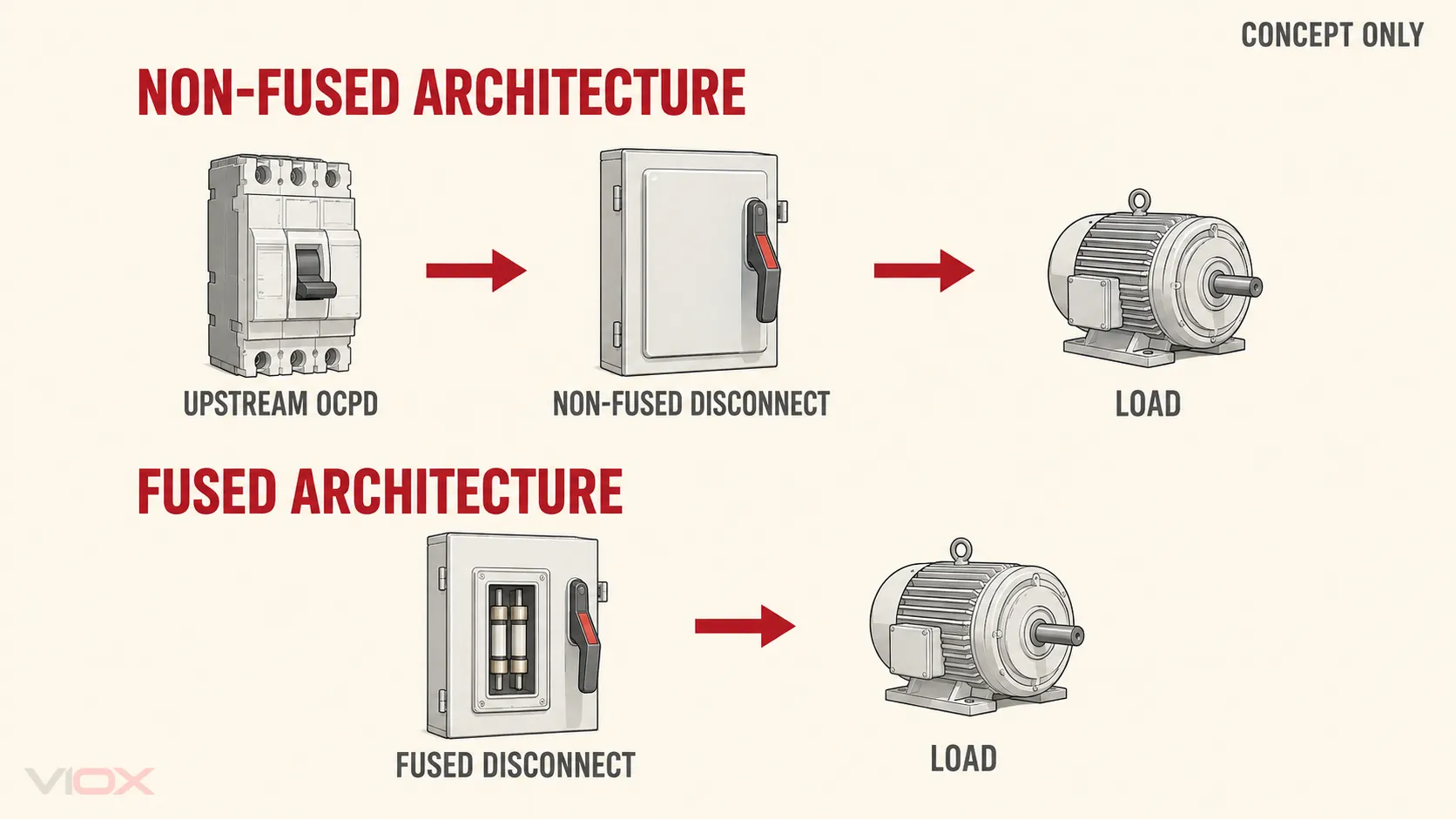
    Fused and non-fused disconnect architectures showing local fuses versus a separate upstream protective device

    What Is a Fused Disconnect Switch?

    A fused disconnect integrates a manually operated switch with fuse positions in one assembly. When properly applied, the switch creates the required disconnected state and the fuses provide overcurrent protection for the circuit or equipment covered by their design.

    The two functions must be evaluated separately:

    • The switching element must be suitable for the required duty. A device intended only for isolation is not automatically suitable for interrupting normal load current.
    • The fuse must have the correct class or type, current rating, voltage rating, interrupting capability, and time-current behavior for the protected circuit.

    The assembly’s performance can also depend on the exact fuse. Substituting a different fuse family merely because it fits physically can invalidate coordination assumptions or a published SCCR. For fuse fundamentals, see the VIOX guide to electrical fuse types, operating principles, and selection.

    What Is a Non-Fused Disconnect Switch?

    A non-fused disconnect switch provides a local means to open the circuit, but it contains no fuses and does not clear overcurrent faults by itself. It must be used within a system that provides the required overcurrent protection elsewhere—commonly through an upstream circuit breaker or fuse.

    This architecture can be entirely appropriate. UL Solutions notes, in its guidance on machinery supply circuits, that the supply disconnect does not necessarily need an integral overcurrent protective device; a non-fused UL 98 disconnect can be used where the system architecture provides the required protection separately.

    However, “there is a breaker upstream” is not enough information on its own. The breaker type and setting, conductors, equipment instructions, available fault current, switch SCCR, and documented combination all matter. A non-fused disconnect simplifies the local device, but it does not remove protection engineering from the circuit.

    If the distinction between isolation, switching, and fault interruption is unclear, start with isolator, disconnector, switch-disconnector, and load-break switch terminology.

    The Core Decision: Where Should Overcurrent Protection Be Located?

    A fused disconnect places fuse protection at the disconnect. A non-fused disconnect separates those functions: the local device disconnects, while another device protects against overcurrent.

    This leads to three common architectures:

    1. Upstream breaker or fuse → non-fused disconnect → load. Use this only when the upstream device correctly protects the conductors and equipment, and the combination meets the required ratings.
    2. Fused disconnect → load. The local assembly provides the disconnecting function and the specified fuse protection.
    3. Upstream protection → fused disconnect → load. Two protective levels may be used for coordination, equipment requirements, or branch-circuit design. The devices must be coordinated; adding fuses without a protection objective is not automatically an improvement.

    The choice therefore begins with a one-line protection statement: which device protects which conductors and which equipment against which fault condition? If that sentence cannot be completed from the drawings, equipment data, and coordination information, the disconnect type has not yet been selected.

    How to Choose: Five Engineering Gates
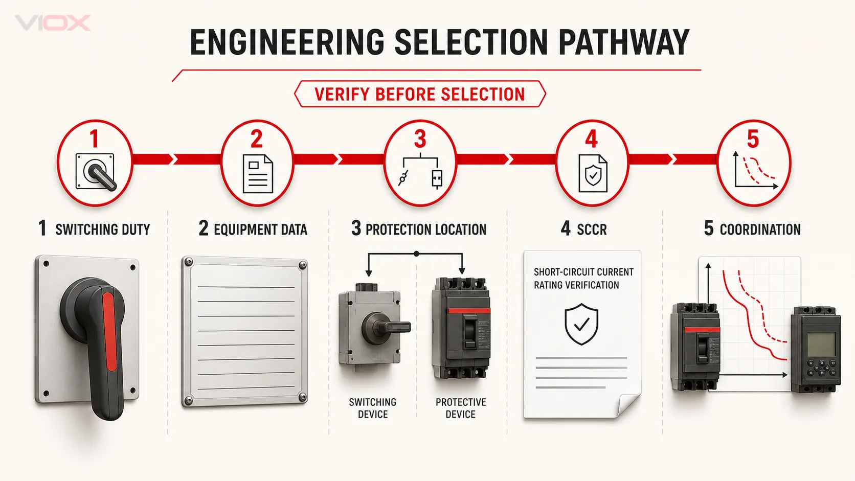
    Five engineering checks for selecting a fused or non-fused disconnect switch

    1. Verify the Required Switching and Isolation Duty

    First define what the operating device must do. Is it an isolating device operated only after the load is removed, or must it make and break normal load current? Does it serve a motor circuit, resistive heater, mixed distribution load, photovoltaic DC circuit, or another duty?

    Under IEC practice, IEC 60947-3 covers switches, disconnectors, switch-disconnectors, and fuse-combination units for low-voltage circuits. The marked utilization category and ratings—not the everyday name “disconnect”—determine the permitted duty. In North American applications, confirm the applicable listing category, such as a UL 98 enclosed or dead-front switch, and any horsepower or application rating required by the design.

    This gate is the same for fused and non-fused devices. Fuses do not upgrade an isolator into a load-break switch.

    2. Read the Equipment Documentation Before Choosing the Protection Type

    Equipment nameplates, installation instructions, and manufacturer tables may specify a maximum protective-device rating, a particular fuse class, an allowed circuit breaker, or a tested combination. Those instructions can decide the fused-versus-non-fused question before cost or convenience is considered.

    For example, if a listed equipment configuration is published only with specified fuses, a fused disconnect may be the practical local solution. If the equipment documentation permits a specified upstream circuit breaker and the local device only needs to disconnect, a non-fused switch may be appropriate.

    Do not copy the device type from an older installation without checking the current equipment data. Two loads with similar current can have different starting behavior, short-circuit requirements, or manufacturer conditions.

    3. Confirm the Protection Location and Scope

    Identify the protective device serving the conductors and load. Then verify what protection it provides. Short-circuit and ground-fault protection, overload protection, residual-current protection, and functional control are different duties; one set of fuses does not automatically replace every required protective or control function.

    Choose a fused disconnect when local fuses are part of the defined branch or equipment protection. Choose a non-fused disconnect when the required protection is already correctly provided and documented upstream.

    For a deeper comparison of devices that disconnect versus devices that automatically interrupt faults, see circuit breaker vs isolator switch.

    4. Compare Available Fault Current With the Documented SCCR

    The available fault current at the installation point must not exceed the rating of the equipment or approved combination. This check applies to both fused and non-fused disconnects.

    A fused assembly may achieve a particular combination SCCR only with a specified fuse class and maximum fuse rating. A non-fused switch may have a documented rating when protected by a specified upstream breaker or fuse. Schneider Electric’s published safety-switch SCCR tables, for example, show that ratings are conditional on the product family and protective-device combination. The lesson is not to borrow Schneider’s values for another product; it is to check the exact manufacturer’s table.

    Do not assume that any fused disconnect has a higher SCCR than any non-fused model. Compare the available fault current with the markings and combination data for the exact devices being specified.

    5. Check Coordination, Operation, and Maintenance

    Protective-device coordination determines which device opens first and how much of the installation is taken offline. Fuse current-limiting behavior and time-current characteristics can be useful in some designs, but the result depends on the selected fuse and the other protective devices. It cannot be inferred from the word “fused.”

    Also consider the operating model:

    • Will qualified personnel have the correct replacement fuse type and rating available?
    • Does the maintenance process prevent unapproved substitutions?
    • Is local fault clearing desirable, or is a centralized upstream protective device preferred?
    • How will personnel identify and investigate the fault before re-energizing?
    • Does the design require visible contact position, door interlocking, padlocking, remote indication, or auxiliary contacts?

    These are lifecycle requirements, not reasons to bypass the electrical checks above.

    Application Examples

    Industrial Machinery

    A machine may use a local non-fused disconnect while a correctly selected upstream device provides supply-circuit protection. This separates the isolation and protection functions and can be valid when the machine documentation, conductor protection, available fault current, and applicable certification support the arrangement.

    A fused disconnect becomes a stronger candidate when the machine builder specifies a fuse-protected supply combination, needs a documented combination SCCR, or places branch protection at the machine entrance. The UL guidance on machine supply circuits is useful for understanding why integral protection is not universal, but the final machine design still requires its own documented evaluation.

    HVAC and Packaged Equipment

    For packaged equipment, start with the nameplate and installation instructions. If the documentation specifies a fuse-only protection condition or a fuse class, use the matching approved architecture. If it permits the specified upstream breaker and the local device is only the service disconnect, a non-fused disconnect may satisfy that role.

    Avoid the shortcut “HVAC always needs fused” or “an upstream breaker always makes fuses unnecessary.” The equipment’s marked conditions and local installation rules decide.

    Distribution and Process Loads

    In a distribution panel or process line, a non-fused switch can provide local isolation while upstream protection remains centralized. A fused switch-disconnector can combine local switching and protection where feeder segmentation, coordination, or documented equipment ratings favor that arrangement.

    When comparing an integrated fused switching device with a simple fuse carrier, see fuse holder vs fuse switch disconnector. A fuse holder should not be assumed to provide the same operating or isolation function as a rated switch-disconnector.

    Common Selection Mistakes

    Treating “Fused” as Automatically Safer

    A correctly engineered fused design and a correctly engineered non-fused design can both be appropriate. Safety depends on the complete system: ratings, protective-device application, enclosure, installation, operation, and maintenance.

    Treating a Non-Fused Disconnect as Fault Protection

    A non-fused switch opens when operated; it does not automatically clear a short circuit or overload. The upstream protection must be identified and checked.

    Assuming Fuses Guarantee a High SCCR

    SCCR is a marked or documented equipment/combination property. It is not created simply by installing fuses. Use the specified fuse and verify the exact manufacturer’s combination table.

    Ignoring AC/DC and Load Duty

    A switch suitable for one voltage, current type, or utilization category may not be suitable for another. DC interruption is particularly dependent on the device’s marked DC rating and pole arrangement. Never transfer an AC selection directly to DC without manufacturer documentation.

    Choosing From Current Rating Alone

    Continuous current is only one input. Voltage, poles, switching category, motor or load duty, available fault current, SCCR, enclosure, ambient conditions, terminals, certifications, and operating accessories can all change the correct product.

    Specification and RFQ Checklist

    Provide the following information when requesting a fused or non-fused disconnect:

    • System voltage, frequency, and AC or DC supply
    • Number of poles and grounding arrangement
    • Continuous current and load type
    • Required switching or isolation duty and operating frequency
    • Motor, horsepower, utilization-category, or application rating where relevant
    • Upstream protective-device type, rating, and setting
    • Equipment maximum protective-device or fuse requirements
    • Available fault current at the installation point
    • Required assembly SCCR or short-circuit rating
    • Required fuse class, size, and characteristics if using a fused design
    • Enclosure/IP or NEMA requirement and environmental conditions
    • Door interlock, padlocking, handle, indication, and auxiliary-contact requirements
    • Required IEC, UL, CSA, or market-specific certification
    • Manufacturer documentation needed to support the selected combination

    If available fault current, coordination, or equipment protection requirements are unknown, resolve those items before ordering. Product selection cannot repair an undefined protection design.

    Final Selection Rule

    Use a fused disconnect switch when specified local fuses are part of the protection design or a documented fuse combination is required. Use a non-fused disconnect switch when suitable upstream overcurrent protection already exists and the complete arrangement meets the equipment, switching-duty, and fault-current requirements.

    The reliable workflow is: verify duty, read the equipment data, define protection location, check SCCR against available fault current, and then assess coordination and maintenance. VIOX supplies switch disconnectors for industrial applications; share the completed checklist with the supplier so the recommendation can be tied to a specific product and documented combination.
    Sources and Standards

  • What Is an HRC Fuse? High Rupturing Capacity Fuse Working Principle, Ratings, and Selection

    What Is an HRC Fuse? High Rupturing Capacity Fuse Working Principle, Ratings, and Selection

    Quick Answer: What Is an HRC Fuse?

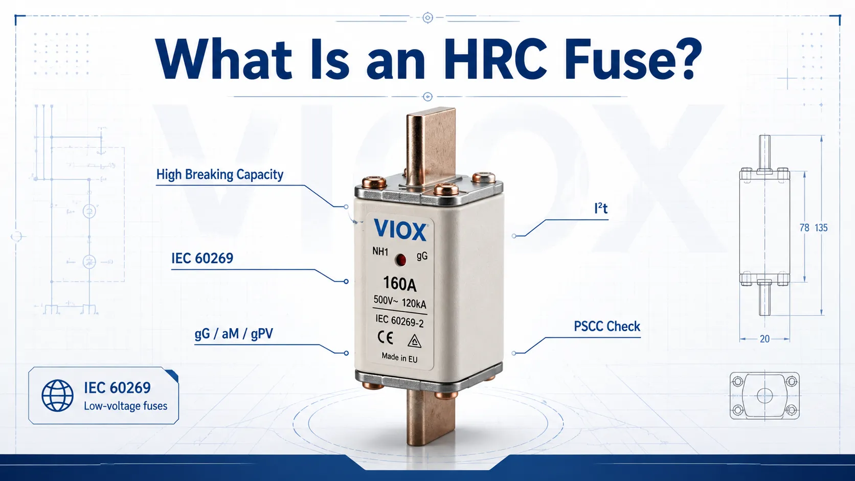
    An HRC fuse, or High Rupturing Capacity fuse, is a current-limiting fuse designed to safely interrupt high prospective short-circuit current without rupturing its body or allowing a sustained arc. It is commonly used in low-voltage industrial panels, distribution boards, motor circuits, transformer feeders, semiconductor protection, solar PV systems, and battery-related DC applications.

    In practical selection, an HRC fuse is not chosen only by ampere rating. You must check:

    • rated current
    • rated voltage, including AC or DC rating
    • breaking capacity against the prospective short-circuit current
    • utilization category such as gG, aM, aR, gR, or gPV
    • I2t let-through energy
    • time-current curve
    • fuse size and holder compatibility
    • coordination with upstream and downstream protection

    If you need the broader fuse family background first, see Electrical Fuses: Types, Working Principle, and Selection Guide. This article focuses specifically on HRC fuse construction, ratings, standards, and selection.

    HRC vs HBC Fuse: Are They the Same?

    In many markets, HRC fuse and HBC fuse are used almost interchangeably.

    Term Meaning Common usage
    HRC fuse High Rupturing Capacity fuse Common in UK, India, and many IEC-oriented markets
    HBC fuse High Breaking Capacity fuse Common in technical datasheets and some European/industrial contexts
    High interrupting fuse Fuse with high fault-current interruption capability Common North American wording

    The wording is slightly different, but the engineering idea is the same: the fuse must be able to interrupt a high fault current safely under its rated conditions.

    For a focused terminology comparison, see HRC vs HBC Fuses: Technical Difference Guide.

    Why “High Rupturing Capacity” Matters

    Every fuse has a breaking capacity, also called interrupting capacity. This is the maximum fault current the fuse can safely interrupt at its rated voltage and specified test conditions.

    The key rule is:

    Fuse breaking capacity >= prospective short-circuit current at the installation point

    If the available fault current is higher than the fuse breaking capacity, the fuse may fail violently, continue arcing, or damage surrounding equipment.

    This is why defining HRC only by a small minimum interrupting-current number is not useful for industrial panels. The relevant value is the actual prospective short-circuit current (PSCC) at the installation point, which may be several kA, tens of kA, or higher depending on transformer size, cable impedance, and system layout.

    For a related breaker-side explanation, see How to Calculate Short Circuit Current for MCB and 6kA vs 10kA MCB Breaking Capacity Guide.

    How an HRC Fuse Works

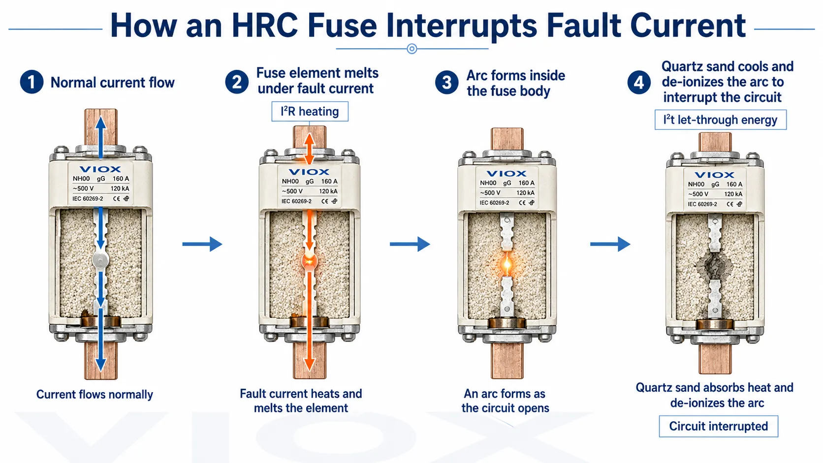
    An HRC fuse operates by melting a calibrated fuse element when current exceeds the fuse’s time-current characteristic. Under heavy fault current, the fuse does more than simply “burn open.” It must interrupt an arc safely.

    Cross-section of an HRC high rupturing capacity fuse showing the fuse element melting and quartz sand filler quenching the arc to limit let-through current during a short-circuit fault
    Inside an HRC fuse, the calibrated element melts under fault current while the quartz sand filler cools and de-ionizes the arc, limiting peak let-through current.

    The operating process is usually:

    1. Fault current rises rapidly.
    2. The fuse element heats according to I2R energy.
    3. One or more element sections melt.
    4. Arcs form inside the fuse body.
    5. Quartz sand or similar filler absorbs heat and helps divide, cool, and de-ionize the arc.
    6. Arc voltage rises and the current is forced to zero.
    7. The circuit is permanently opened and the fuse link must be replaced.

    The current-limiting behavior is one of the major advantages of HRC fuses. In a high fault, a properly selected HRC fuse can limit the peak let-through current and reduce the thermal and mechanical stress imposed on downstream equipment.

    HRC Fuse Construction

    Most industrial HRC fuse links use a robust cartridge construction.

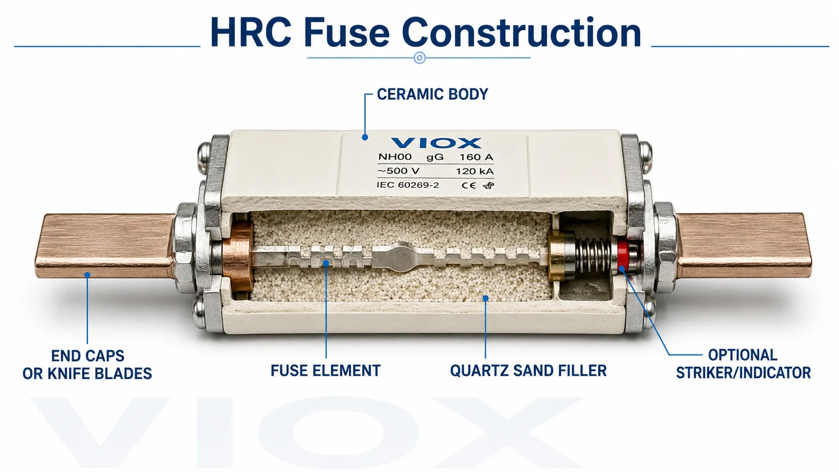
    Construction diagram of an HRC fuse link with ceramic body, silver or copper fuse element, quartz sand filler, end caps or knife blades, and optional striker indicator rated NH00 160A gG 500V 120kA per IEC 60269-2
    HRC fuse construction: ceramic body, fuse element, quartz sand filler, end caps or knife blades, and an optional striker or indicator (example: NH00, 160 A, gG, 500 V, 120 kA, IEC 60269-2).
    Component Function
    Ceramic or porcelain body Withstands high temperature, pressure, and arc energy during fault interruption
    Fuse element Calibrated conductive element, commonly silver or copper-based depending on design
    Quartz sand filler Absorbs heat, cools the arc, and helps form a high-resistance arc path
    End caps or knife blades Provide electrical connection to the holder, base, or fuse switch disconnector
    Indicator or striker, if fitted Gives visual indication or actuates a microswitch/trigger mechanism after operation

    Not every HRC fuse has the same internal element design. Some use notches, parallel element sections, M-effect features, striker pins, or special semiconductor-speed elements. That is why two fuses with the same ampere rating can behave very differently if their utilization category and time-current curve are different.

    Key HRC Fuse Ratings Explained

    Parameter What it means Why it matters
    Rated current (In) Current the fuse can carry under specified conditions Must match the protected cable, load, and utilization category
    Rated voltage Maximum circuit voltage for safe operation AC and DC ratings must be checked separately
    Breaking capacity Maximum fault current the fuse can interrupt safely Must exceed PSCC at the installation point
    Utilization category Fuse operating behavior, such as gG, aM, aR, gPV Determines whether the fuse protects cables, motors, semiconductors, PV strings, etc.
    Time-current curve Relationship between current magnitude and operating time Required for selectivity, motor starting, and coordination
    I2t Energy let through during melting and clearing Critical for semiconductor protection and thermal damage limitation
    Power dissipation Heat produced by the fuse at rated current Affects enclosure temperature and fuse holder selection
    Fuse size and format NH, cylindrical, D/D0, semiconductor style, PV fuse, etc. Must match the physical holder and disconnector

    IEC 60269 Fuse Categories: gG, aM, aR, gPV, and More

    IEC 60269 is the major international standard family for low-voltage fuses. In IEC terminology, the replaceable part is often called a fuse-link, while the complete assembly may include the fuse-link and fuse holder or fuse base.

    The utilization category tells you what the fuse is designed to protect.

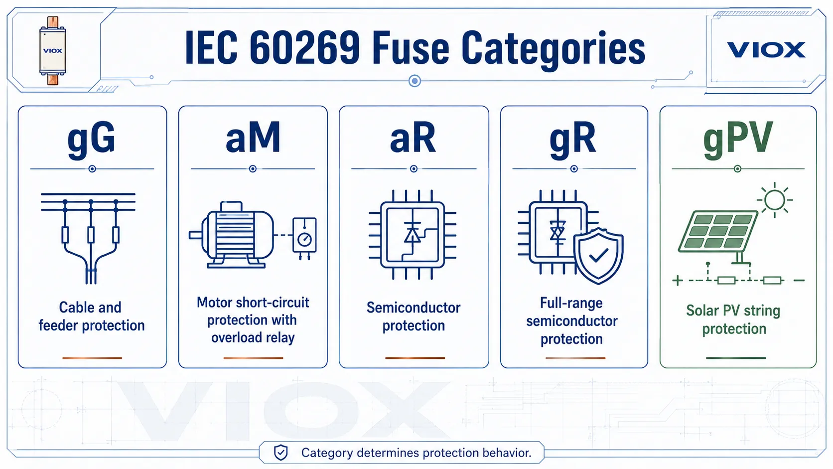
    IEC 60269 fuse utilization category chart showing gG for cable and feeder protection, aM for motor short-circuit protection, aR and gR for semiconductor protection, and gPV for solar PV string protection
    IEC 60269 utilization categories map each fuse class to its protection role: gG for cables, aM for motors, aR/gR for semiconductors, and gPV for solar PV strings.
    Category Main function Typical use Selection warning
    gG Full-range general-purpose protection Cables, lines, general distribution circuits Common choice for cable and feeder protection
    aM Partial-range motor short-circuit protection Motor circuits with separate overload relay Does not provide full overload protection by itself
    aR Partial-range semiconductor protection Rectifiers, drives, power electronics Very fast, but must be coordinated with the semiconductor device
    gR Full-range semiconductor protection Semiconductor and converter protection Check manufacturer curves and I2t data carefully
    gPV Photovoltaic string protection Solar PV combiner boxes and DC arrays Requires DC voltage and PV-specific rating
    Battery-related categories Battery and energy storage protection BESS and DC battery circuits Must be selected from the exact fuse standard, datasheet, and system fault profile

    The first letter matters:

    • g generally indicates full-range breaking capability, covering overload and short-circuit conditions within the fuse’s defined range.
    • a generally indicates partial-range protection, typically for short-circuit protection only; another device must provide overload protection.

    This is a major selection point. For example, an aM motor fuse is not a direct replacement for a gG cable protection fuse unless the protection scheme is designed for it.

    For deeper IEC 60269 selection guidance, see IEC 60269 Low Voltage Fuse Selection Guide: gG, aM, and NH Fuses.


    Main Types of HRC Fuses

    NH HRC Fuses

    NH fuses are widely used in industrial low-voltage distribution. They normally have a rectangular ceramic body and knife-blade contacts. They are commonly used with NH fuse bases, fuse switch disconnectors, or switch-fuse combinations.

    Typical applications include:

    • main distribution boards
    • feeder circuits
    • transformer secondary protection
    • motor feeders
    • industrial control panels
    • utility and building distribution

    NH fuse selection must include the fuse size, rated current, voltage, breaking capacity, utilization category, and matching holder or fuse switch disconnector.

    Cylindrical HRC Fuses

    Cylindrical HRC fuses are compact cartridge fuses used in control panels, small distribution circuits, control transformers, instrumentation, and some power circuits.

    They are not automatically interchangeable just because the diameter and length match. Voltage, current, breaking capacity, utilization category, and holder rating still matter.

    D and D0 Type Fuses

    DIAZED and NEOZED-style fuses are used in some European-style distribution systems. They are usually associated with screw-type fuse bases and gauge rings that help prevent installing a fuse above the intended rating.

    These are not the same as NH fuses, and they should not be treated as interchangeable.

    Semiconductor Fuses

    Semiconductor fuses are designed for very fast energy limitation. They protect:

    • rectifiers
    • inverters
    • drives
    • UPS systems
    • solid-state devices
    • power converters

    The critical data is not just current rating. I2t, peak let-through current, voltage rating, and coordination with the semiconductor device are essential.

    PV and DC HRC Fuses

    Solar PV and battery systems require DC-rated fuses. DC arcs do not naturally extinguish at a current zero the way AC arcs do, so the fuse must be tested and rated for the actual DC voltage and fault conditions.

    For PV systems, use PV-rated fuses such as gPV where required. For DC fuse fault duties, see DC Fuse Breaking Capacity for PV Systems and How to Properly Fuse a Solar Photovoltaic System.

    HRC Fuse vs Fuse Link vs Fuse Holder

    These terms are often mixed together, but they are not the same.

    Item Meaning Why it matters
    Fuse link Replaceable cartridge or blade component that melts during a fault Must match current, voltage, class, size, and curve
    Fuse holder/base Mechanical and electrical support for the fuse link Must match heat, current, voltage, and short-circuit conditions
    Fuse switch disconnector Switching device that includes fuse links and isolation/switching function Must be rated for switching duty and safe operation
    Fuse assembly Complete protective arrangement Performance depends on all matched parts

    Do not select the fuse link alone and ignore the holder. Poor contact pressure, wrong size, low-quality terminals, or mismatched fuse bases can cause overheating even when the fuse link rating is correct.

    For the terminology split, see Fuse vs Fuse Link Difference Guide. For installation hardware, see Fuse Holder vs Fuse Switch Disconnector.

    HRC Fuse vs MCB and MCCB

    HRC fuses and circuit breakers both protect electrical circuits, but they do it differently.

    Feature HRC fuse MCB / MCCB
    Operation after fault Single-use, replace fuse link Resettable after trip, subject to inspection
    Fault interruption Very high and fast current-limiting capability possible Depends on breaking capacity and trip unit design
    Overload adjustment Fixed by fuse type and curve MCCBs may offer adjustable settings
    Indication Some fuses have indicators or strikers Breakers show trip/open/closed state more directly
    Remote control Not normally Possible with accessories on some breakers
    Selectivity Strong when coordinated with fuse curves Strong when coordinated with breaker settings
    Maintenance focus Holder condition, contact pressure, correct replacement Mechanism, contacts, trip unit, accessories

    Use an HRC fuse when high fault-current limitation, compact protection, and simple replacement are priorities. Use a breaker when resettable operation, switching function, adjustable protection, or monitoring are required.

    For a more detailed comparison, see Fuse vs MCB Response Time and What Is the Difference Between Fuse and Circuit Breaker?.


    How to Select an HRC Fuse

    Use this sequence instead of choosing only by ampere rating.

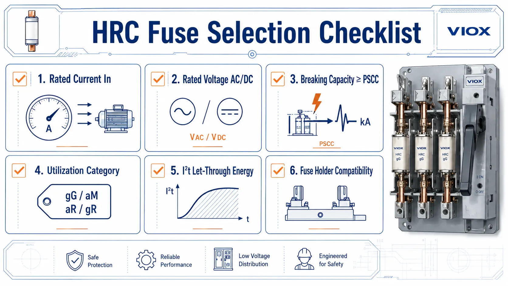
    HRC fuse selection checklist with six steps rated current, rated voltage AC or DC, breaking capacity greater than or equal to PSCC, utilization category gG aM aR gR, I2t let-through energy, and fuse holder compatibility for VIOX gG fuses
    HRC fuse selection checklist: rated current, AC/DC voltage, breaking capacity >= PSCC, utilization category, I2t let-through energy, and fuse holder compatibility.

    Step 1: Identify the circuit application

    Ask what the fuse is protecting:

    • cable or feeder
    • motor circuit
    • transformer
    • capacitor bank
    • semiconductor device
    • PV string
    • battery circuit
    • control transformer
    • general distribution

    Different applications require different fuse categories and curves.

    Step 2: Match the rated voltage

    The fuse voltage rating must be equal to or higher than the system voltage. AC and DC ratings are not interchangeable.

    For DC systems, confirm:

    • maximum DC voltage
    • polarity requirements, if any
    • DC breaking capacity
    • PV or battery-specific standard and category
    • manufacturer wiring and installation instructions

    Step 3: Match the rated current

    Rated current must protect the cable and load correctly. Do not oversize the fuse just to avoid nuisance operation.

    For motor circuits, consider starting current and starting time. A motor circuit may require an aM fuse with an overload relay or motor protection device. For cable feeders, a gG fuse may be more appropriate.

    Step 4: Check breaking capacity against PSCC

    Calculate or obtain the prospective short-circuit current at the installation point. Then confirm:

    Fuse breaking capacity >= PSCC

    If the fuse is installed near a transformer or main busbar, PSCC may be much higher than at a downstream final circuit.

    Step 5: Check utilization category

    Do not replace:

    • gG with aM without reviewing overload protection
    • semiconductor fuse with general-purpose fuse
    • PV fuse with ordinary AC fuse
    • DC battery fuse with an AC-only fuse

    The utilization category is a functional rating, not a marketing label.

    Step 6: Review I2t and selectivity

    For coordination, compare melting I2t and clearing I2t with downstream and upstream devices. In semiconductor circuits, I2t is often one of the most critical parameters because the fuse must limit energy before the protected device is damaged.

    Step 7: Confirm fuse holder and disconnector compatibility

    Check:

    • physical size
    • rated current of holder
    • voltage rating
    • heat dissipation
    • contact pressure
    • terminal capacity
    • mounting style
    • fuse switch disconnector rating, if used

    An HRC fuse link is only as good as the holder and connection system around it.

    Common HRC Fuse Selection Mistakes

    Mistake 1: Treating HRC as one universal fuse type

    HRC describes high breaking capacity, but it does not define the application category. gG, aM, aR, gR, gPV, and other categories behave differently.

    Mistake 2: Using AC voltage data for DC circuits

    DC interruption is more demanding because there is no natural current zero. Always check the DC voltage and DC breaking capacity.

    Mistake 3: Oversizing the fuse to avoid nuisance blowing

    Oversizing may stop nuisance operation, but it can leave cables or equipment under-protected.

    Mistake 4: Ignoring I2t

    For semiconductor, drive, UPS, rectifier, and power electronics protection, I2t can be more important than the ampere rating alone.

    Mistake 5: Replacing only the fuse link without checking the holder

    Overheated fuse holders, weak contact pressure, corrosion, and wrong base size can cause failures even with a correct fuse link.

    Mistake 6: Using ordinary fuses in PV or battery systems

    PV strings and battery systems have DC fault behavior that requires suitable DC-rated fuse links and correct coordination.

    Mistake 7: Removing a fuse under load without the right device

    A fuse holder is not automatically a load-break switch. If switching is required, use a properly rated fuse switch disconnector or switch-fuse device.


    FAQ

    What does HRC fuse mean?

    HRC fuse means High Rupturing Capacity fuse. It is designed to safely interrupt high fault current without the fuse body rupturing or allowing a sustained arc.

    Is HRC the same as HBC?

    In most practical industrial discussions, HRC and HBC describe the same concept: a fuse with high fault-current breaking capability. HRC means High Rupturing Capacity, while HBC means High Breaking Capacity.

    What is the difference between gG and aM fuses?

    A gG fuse is a full-range general-purpose fuse often used for cable and feeder protection. An aM fuse is a partial-range motor fuse intended mainly for short-circuit protection and normally requires separate overload protection.

    What is I2t in an HRC fuse?

    I2t describes energy let-through during fuse operation. It is used for protection coordination and is especially important when protecting semiconductors, drives, rectifiers, and other sensitive power electronics.

    Can an HRC fuse be reused after it blows?

    No. The fuse link is a single-use protective device. After operation, replace it with the correct type, current rating, voltage rating, utilization category, and size.

    Can I replace an HRC fuse with an MCB?

    Not automatically. An MCB must have suitable rated current, trip curve, breaking capacity, voltage rating, and coordination for the circuit. HRC fuses and MCBs behave differently, especially under high fault current.

    Can HRC fuses be used in DC circuits?

    Yes, but only if the fuse is specifically rated for the DC voltage, breaking capacity, and application. Do not assume an AC HRC fuse is suitable for DC, PV, or battery systems.

    Why did my HRC fuse not blow during motor starting?

    That may be normal if the fuse and motor circuit were selected correctly. Motor starting current is temporary. Motor circuits often use a fuse type and overload protection arrangement that allows starting current while still protecting against short circuits.

    What should I check when an HRC fuse holder is hot?

    Check load current, fuse rating, terminal torque according to manufacturer instructions, contact pressure, corrosion, fuse holder rating, cable size, and whether the fuse link is correctly seated. Heat often comes from contact resistance, not only from fuse current rating.

    Which standard applies to HRC fuses?

    For IEC markets, low-voltage fuses are commonly specified under the IEC 60269 series. North American applications may involve UL 248 fuse standards. The correct standard depends on product type, market, voltage, and application.


    Summary

    An HRC fuse is a high breaking capacity protective device used where fault current can be severe and fast, reliable interruption is required. Its strength comes from a carefully designed fuse element, ceramic body, arc-quenching filler, and tested breaking capacity.

    The correct selection is not simply “choose the same ampere rating.” Engineers and panel builders must check rated voltage, AC/DC duty, breaking capacity, utilization category, I2t, time-current curve, fuse holder compatibility, and coordination with the rest of the system.

    For VIOX fuse-related guidance, start with the Fuse product category, then review the supporting guides on IEC 60269 fuse selection, fuse holder vs fuse switch disconnector, and DC fuse breaking capacity for PV systems.


    Sources Used

  • What Causes Solar Panels to Catch Fire? A Complete Safety Guide

    What Causes Solar Panels to Catch Fire? A Complete Safety Guide

    Solar panels have become increasingly popular as homeowners and businesses seek clean, renewable energy solutions. However, with this growth comes important safety considerations—including the rare but serious risk of solar panel fires. While the overall fire risk is extremely low, understanding what causes solar panels to catch fire is crucial for protecting your property and maximizing your investment.

    Bottom Line Up Front: Solar panel fires are extremely rare (affecting only 0.006% of systems), but when they occur, poor installation practices account for 50% of incidents. The good news? Nearly all solar panel fires are preventable through proper installation, quality components, and regular maintenance.

    Understanding Solar Panel Fire Risk: The Real Statistics

    solar panel

    Before diving into causes, let’s put the risk in perspective. According to government data, in the UK there were 66 fires caused by solar panels in the first half of 2023, compared to over 1.4 million properties with solar installations. A study in Germany found that out of 1.4 million solar power systems, only 0.006% were linked to fire incidents.

    The apparent increase in solar panel fire reports isn’t due to the technology becoming more dangerous—it’s simply because the number of households adopting solar has skyrocketed. Between 2018 and 2023, global solar capacity tripled. As one industry expert noted, “As an industry, we didn’t start installing solar panels on a large scale until 2013 or 2014. Those systems that are not being maintained are hitting 10 to 12 years old and it is some of these that are causing fires.”

    Top 6 Causes of Solar Panel Fires

    1. Poor Installation Practices (Leading Cause)

    The most significant factor: A 2022 study from the University of Edinburgh found that 50% of solar panel fires are caused by internal issues stemming from faulty installations. Poor installation practices create multiple fire hazards:

    Common Installation Errors:

    • Faulty wiring and loose electrical connections
    • Improper grounding of the system
    • Inadequate ventilation around panels
    • Incorrect sizing of cables and components
    • Poor junction box assembly and connector seaming

    When electrical connections aren’t properly secured, they create resistance that generates heat. Over time, this can cause wires to overheat, melt insulation, and potentially ignite surrounding materials.

    The Professional Installation Solution: As Alistair Bambrook, risk management director at Towergate, noted: “If solar panels are installed correctly by a certified installer and regularly maintained, they should operate effectively with few issues. Problems arise when panels are installed incorrectly, using poor-quality components, or when electrical connections are not secured properly.”

    2. Electrical Faults and Arc Faults

    Electrical problems are responsible for a significant portion of solar panel fires. According to the International Association for Fire Safety Science, faulty electrical connections are responsible for nearly 25% of PV-related fires.

    Key Electrical Hazards:

    • DC Arc Faults: High-voltage DC current ‘jumps’ through the air when two conductors are close enough together. The heat from a DC arc can get so hot, the surrounding material can easily catch fire.
    • Ground Faults: Electricity flowing where it shouldn’t, creating dangerous heating.
    • Short Circuits: Direct electrical contact causing immediate overheating.
    • Inverter Malfunctions: The heart of your solar system can overheat and potentially ignite.

    The challenge with DC systems is that once an arc fault is triggered, it can be difficult to stop because the voltage in DC systems is constant, and you have to be able to interrupt the circuit or the arcing will continue.

    3. Hot Spots from Shading and Debris

    Hot spots represent one of the most common degradation modes in solar panels. A hot spot is a localized area of a solar panel that overheats due to obstruction or shading, causing the panel to generate heat instead of electricity.

    What Causes Hot Spots:

    • Partial shading from trees, buildings, or equipment
    • Debris accumulation (leaves, bird droppings, dust)
    • Manufacturing defects in individual cells
    • Cell mismatches within the panel

    The Physics Behind Hot Spots: When debris partially shades a panel, the affected cells act as resistors rather than conductors, causing an obstruction to the current. This results in localized overheating, which can eventually cause a fire if left unaddressed.

    The Concerning Reality: Once a hot spot forms, it tends to worsen over time, as heat continues to concentrate in that area, eventually damaging the panel irreparably.

    4. Component Defects and Equipment Failure

    Manufacturing defects and low-quality components significantly increase fire risk. Several areas are particularly vulnerable:

    Critical Component Issues:

    • Junction Box Problems: Located on the back of panels, these connection points are prone to failure if poorly manufactured.
    • Faulty Bypass Diodes: When these safety devices fail, they can’t prevent reverse current flow.
    • Inverter Defects: Can cause overheating and electrical faults.
    • Poor Quality Backsheets: Inadequate insulation materials that can’t handle heat buildup.

    Historical Context: There have been notable cases of widespread component failures, such as fire incidents reported in 2012 in relation to photovoltaic installations equipped with defective Scheuten Multisol® modules manufactured between September 2009 and October 2010. 

    5. Environmental Factors

    External conditions can create or exacerbate fire risks:

    Environmental Threats:

    • Extreme Heat: Can cause insulation breakdown and component degradation.
    • Moisture Infiltration: Leads to corrosion and electrical faults.
    • Lightning Strikes: Can damage electrical components.
    • High Winds: May loosen connections or damage mounting systems.
    • Nearby Fires: Can spread to solar installations.

    In very hot climates, overheating can lead to insulation breakdown and electrical faults, while moisture can compromise the integrity of electrical connections.

    6. Aging Systems and Lack of Maintenance

    As solar systems age, the risk of failure increases without proper maintenance. Studies show that aged PV modules are more prone to faults that increase fire risk. After 20 years, the probability of failure can increase by up to 15% if regular maintenance is not conducted.

    Age-Related Risk Factors:

    • Degraded cables and connections
    • Accumulated debris and soiling
    • Component wear and fatigue
    • Reduced insulation effectiveness
    • Unaddressed minor issues that compound over time

    How to Prevent Solar Panel Fires

    The overwhelming majority of solar panel fires are preventable. Here’s how to minimize your risk:

    Choose Professional Installation

    Critical First Step: Work only with certified, experienced installers who hold proper licenses and MCS (Microgeneration Certification Scheme) accreditation. Avoid DIY installations, as they significantly increase fire risk.

    Invest in Quality Components

    High-quality, certified components from reputable manufacturers dramatically reduce fire risk. Look for:

    • Integrated arc-fault detection devices
    • Quality inverters with safety certifications
    • Proper bypass diodes and safety systems

    Implement Regular Maintenance

    Essential Maintenance Tasks:

    • Visual Inspections: Check for loose connections, damaged cables, or signs of wear.
    • Thermal Imaging: Professional inspections can identify hot spots before they become dangerous.
    • Cleaning: Remove debris, leaves, and soiling that can cause hot spots.
    • Electrical Testing: Verify connections and system performance.

    Ensure Proper System Design

    Design Considerations:

    • Adequate spacing between panels for ventilation.
    • Proper grounding and electrical isolation.
    • Clear access pathways for maintenance and emergency response.
    • Appropriate system sizing and component matching.

    Warning Signs to Watch For

    Be alert for these potential indicators of fire risk:

    Visual Warning Signs:

    • Brown or discolored spots on panels.
    • Visible damage to cables or connections.
    • Burn marks around junction boxes.
    • Warped or damaged panel surfaces.

    Performance Indicators:

    • Sudden drops in power production.
    • Individual panel underperformance.
    • Inverter error messages or shutdowns.
    • Unusual heat generation from components.

    What to Do If Your Solar Panel Catches Fire

    Immediate Safety Steps:

    1. Call Emergency Services: Contact fire department immediately.
    2. Stay Away: Don’t attempt to extinguish electrical fires yourself.
    3. Disconnect if Safely Possible: Shut off the system at the main disconnect if accessible.
    4. Never Use Water: Solar panels should under no circumstances be doused with water before they are disconnected.
    5. Inform First Responders: Alert firefighters that solar panels are present on the property.

    Important Safety Note: PV systems can pose several hazards during firefighting efforts, including the risk of electrical shock from live system components, especially due to electrical current flowing through water.

    The Future of Solar Panel Fire Safety

    Technology continues to improve solar panel fire safety. Modern systems include enhanced safety features like:

    • Automatic shutdown capabilities during faults.
    • Advanced arc-fault detection.
    • Module-level power electronics that isolate problems.
    • Improved component designs and materials.

    Industry Recommendation: Leading industry groups continue to fight for improved safety standards and industry oversight to help protect households from buying outdated technology that can be a fire risk.

    Conclusion: Solar Panels Are Safe When Done Right

    While solar panel fires can occur, they remain extremely rare and are almost always preventable. The key factors for safety are professional installation, quality components, and regular maintenance. By understanding the causes and taking appropriate precautions, homeowners can enjoy the benefits of solar energy with confidence.

    Key Takeaways:

    • Solar panel fire risk is extremely low (0.006% of systems).
    • 50% of incidents are due to poor installation practices.
    • Regular maintenance and professional installation are your best protection.
    • Modern safety technology continues to improve system reliability.

    When considering solar panels, don’t let fear of fire risk deter you from this valuable clean energy technology. Instead, use this knowledge to make informed decisions about installation and maintenance that will keep your system safe and productive for decades to come.

    Related

    What Does a Solar Combiner Box Do?

    How to Choose the Right SPD for Your Solar Power System

  • Why Does an MCB Keep Tripping? Diagnose Repeated Trips Safely

    Why Does an MCB Keep Tripping? Diagnose Repeated Trips Safely

    If an MCB keeps tripping, the circuit is usually reaching the breaker’s thermal or instantaneous pickup region repeatedly—or an installation or device condition is affecting the protective mechanism. Do not solve repeated tripping by repeatedly resetting the breaker or installing a higher current rating. First identify which protective device operated, note when it trips, remove only safely accessible loads, and stop if the circuit shows signs of damage.

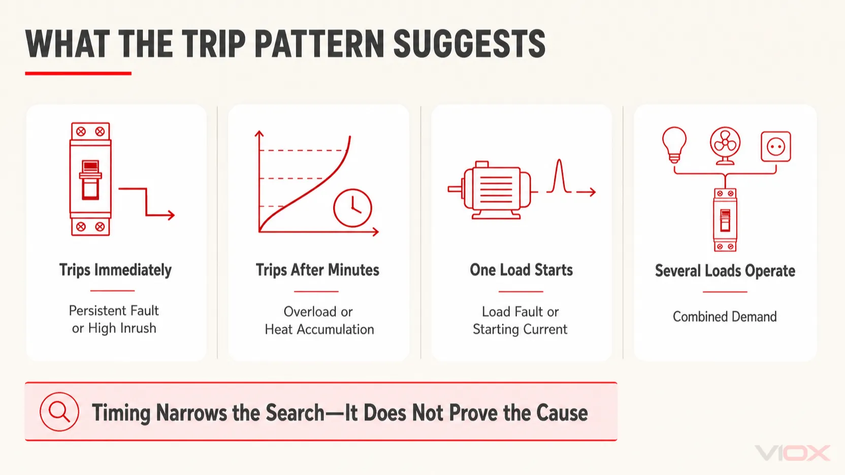
    Trip timing is a useful clue, not a final diagnosis. An immediate trip may indicate a short circuit, but high starting current can also enter the magnetic pickup range. A trip after several minutes often points toward sustained overload or accumulated heat, but it can also involve a poor connection, high ambient temperature, damaged equipment, or an unsuitable installation.

    Key Takeaways

    • Trips immediately: suspect a persistent fault or very high inrush current; do not keep resetting it.
    • Trips after a few minutes: investigate sustained current and heating rather than assuming the MCB is defective.
    • Trips when one load starts: isolate that load and verify its condition, starting current, and protective-device coordination.
    • Trips only with several loads: the combined demand may exceed the circuit’s intended capacity.
    • Trips with no accessible loads connected: leave the circuit off and arrange qualified testing.
    • Burning odor, discoloration, melted insulation, crackling, sparking, water exposure, or unusual panel heat: stop troubleshooting and contact a qualified electrician.

    First Confirm Which Device Is Tripping

    People often use “MCB” to describe every device in a distribution board. That can send the diagnosis in the wrong direction because an MCB and a residual-current device respond to different electrical quantities.

    Device that operated Common identification clues What normally causes it to operate Diagnostic implication
    MCB Current rating such as 16 A or 32 A; IEC-style products may show B, C, or D before the rating Overcurrent through the protected pole: sustained overload or current in the instantaneous pickup region Focus on circuit current, inrush, short circuit, thermal conditions, connections, and breaker condition
    RCCB/RCD Test button and residual-current marking such as IΔn; may show 30 mA, 100 mA, or 300 mA Residual-current imbalance; it does not provide integral overcurrent protection Focus on leakage, insulation, moisture, neutral-to-earth problems, and cumulative leakage
    RCBO MCB-style current/curve marking plus a test button and residual-current marking Either overcurrent or residual current, depending on the event and device indication Determine which protection function operated before selecting the test path

    A standard MCB is not a residual-current device and does not provide additional protection based on residual current. An earth fault may operate an MCB if the resulting overcurrent reaches its trip threshold, but the MCB must not be treated as a substitute for an RCCB, RCBO, or—where North American terminology applies—a GFCI.

    Diagnose the Pattern Before You Reset

    The following matrix is designed to narrow the investigation without pretending that one observation proves the cause.

    What you observe Likely direction What would strengthen the diagnosis Safe next action
    MCB trips immediately after one reset attempt Persistent short circuit, damaged wiring or load, or starting current entering the instantaneous range It still trips with all safely accessible loads switched off or unplugged; damage or odor is present Leave the circuit off. Do not repeat the reset. Arrange qualified testing
    MCB trips after a few minutes or about 10 minutes Sustained overload, thermal accumulation, warm enclosure, adjacent-device heating, poor connection, or equipment drawing excessive current Trip time shortens as load or panel temperature rises; measured current or thermal inspection identifies an abnormal condition Reduce accessible load. If recurrence remains, keep the circuit off and test current, connections, and thermal conditions
    MCB trips only when one appliance or machine starts Faulty equipment, high starting current, stalled motor, unsuitable trip characteristic, or undersized circuit The event consistently follows the same load command; startup-current measurement or equipment testing identifies the cause Disconnect the suspected load and have it checked. Do not test a damaged appliance on another circuit
    MCB trips only when several loads run together Combined load exceeds the circuit design or one load is drawing more than expected The circuit remains stable when high-demand loads are not operated together; current measurement confirms the loading pattern Stop simultaneous operation. Have circuit capacity and load allocation reviewed if this is a recurring operating need
    MCB trips randomly, later in the day, or when the panel is warm Intermittent equipment cycle, ambient heating, dense-device heating, loose or oxidized connection, or an intermittent wiring fault Event timing follows temperature, an automatic load cycle, moisture, or an identifiable operating state Record the operating pattern. Qualified personnel should inspect and measure rather than guessing from the handle position
    MCB will not reset or stay on with accessible loads removed Fixed wiring fault, internal equipment still connected, damaged breaker, incomplete mechanical reset, or another protection device actually operated Correct device identification and a proper OFF-to-ON reset do not restore the circuit Leave it off. Do not open the panel or replace the breaker without testing the circuit
    MCB trip patterns suggesting persistent fault, overload, starting current, or combined demand

    For a deeper evidence-based distinction between overload, short circuit, and an inconclusive trip, see How to Know Why a Breaker Tripped. That separate guide explains why timing alone cannot identify the operated protection function with certainty.

    Stop Immediately if There Are Signs of Damage

    Do not attempt another reset if any of the following is present:

    • persistent burning or acrid odor;
    • visible discoloration, melted insulation, or a deformed breaker enclosure;
    • sparking, crackling, buzzing, or signs of arcing;
    • smoke, fire damage, or water inside or near electrical equipment;
    • an electric shock or tingling sensation from connected equipment;
    • a panel cover or breaker area that is unusually hot compared with similar loaded circuits;
    • immediate retripping after accessible loads have been disconnected;
    • uncertainty about which device operated or which circuit it controls.

    Switch off the affected circuit if this can be done without approaching damaged equipment. For smoke, fire, or a visibly unsafe panel, follow local emergency procedures and do not touch the equipment.

    Why an MCB Trips After a Few Minutes or About 10 Minutes

    A delayed trip commonly involves the MCB’s thermal release. Current heats a bimetal element, and the time required to release the mechanism depends on current magnitude, prior loading, ambient temperature, neighboring devices, conductor heat flow, and the product’s time-current characteristic.

    This inverse-time behavior means there is no universal “10-minute fault.” Higher sustained overcurrent generally produces a faster thermal response, while a smaller overload may take longer. Manufacturer trip curves show a tolerance band, not one exact operating time. The mechanism is explained in more depth in How Does an MCB Work?.

    Sustained overload is the first condition to check

    An overload exists when the operating current exceeds what the circuit and protection arrangement are intended to carry for the relevant duration. Common operating patterns include:

    • several heating appliances or other high-demand loads on one final circuit;
    • a motor, compressor, or pump drawing excessive running current;
    • a machine operating in a mechanically overloaded or stalled condition;
    • added equipment increasing the demand beyond the original circuit design;
    • a load whose current has risen because of an internal fault or degraded operating condition.

    For a simple resistive single-phase load, current can be estimated approximately as:

    I ≈ P / V

    This estimate is not sufficient for motors, electronic power supplies, nonlinear loads, or equipment with significant power-factor and efficiency effects. A qualified person should measure operating and starting current and compare the results with the equipment data, conductor capacity, MCB rating, installation conditions, and applicable design rules.

    Do not apply a universal “80% rule” to every installation. Continuous-load rules and conductor/protection requirements depend on the applicable code, device standard, conductor system, installation method, and market.

    Ambient and adjacent-device heat can move the trip point

    Thermal-magnetic MCBs are calibrated under declared conditions. A hot enclosure, dense rows of loaded devices, inadequate ventilation, or a recently tripped breaker can place the thermal release closer to operation. ABB’s published MCB guidance notes that thermal behavior depends on ambient temperature and that designers should use the manufacturer’s current-correction data for the specific series.

    The correct response is not to assume that the breaker is “too sensitive.” Verify the actual current, panel temperature, device spacing or correction requirements, conductor loading, and product documentation.

    A loose connection is a heating hazard, not an automatic diagnosis

    A loose, contaminated, or oxidized termination can create high contact resistance and localized heating. That condition does not necessarily create enough overcurrent to trip an MCB directly. Repeated tripping may occur if heat is conducted into the breaker’s thermal system, if the connection damages insulation and develops into a fault, or if the load and thermal conditions together cross the trip characteristic.

    Do not remove a panel cover or retorque terminals as a DIY test. Qualified personnel should de-energize and secure the equipment, inspect for damage, verify connections using the manufacturer’s specified method and torque data, and compare thermal measurements under known load conditions. Schneider Electric’s troubleshooting guidance specifically includes overheating at loose or oxidized wire and bus connections as a condition that must be investigated.

    Why an MCB Trips Immediately After Resetting

    A magnetic release responds rapidly when overcurrent reaches its instantaneous pickup range, typically during a short circuit. However, an immediate trip does not prove that a short circuit exists.

    Possible causes include:

    • phase-to-neutral or phase-to-phase short circuit;
    • damaged cable insulation or a fault in fixed wiring;
    • an appliance or machine with an internal short circuit;
    • a motor, transformer, power supply, lamp driver, or capacitor bank with starting current above the MCB’s instantaneous pickup band;
    • a mechanically stalled motor drawing high current;
    • an unsuitable MCB characteristic for a properly designed high-inrush load;
    • incorrect wiring or a damaged protective device.

    If the MCB immediately trips again after accessible loads have been switched off or unplugged, leave it off. Repeated closing onto a fault can impose additional electrical and mechanical stress on the circuit and switching device.

    Why the MCB Trips When One Appliance or Machine Starts

    When one load consistently triggers the trip, there are two broad possibilities:

    1. The load is abnormal. Damaged insulation, an internal short circuit, a stalled motor, worn mechanical parts, or a defective power supply can produce excessive current.
    2. The load is healthy but poorly coordinated with the circuit. Starting or energization current may enter the MCB’s instantaneous pickup band even though steady-state current is acceptable.

    The safe first action is to stop using and disconnect the suspected load if it can be unplugged or isolated through its normal controls. Do not move a suspect appliance to another circuit merely to see whether another breaker trips. Have the equipment inspected or tested according to its product instructions.

    For a fixed or industrial load, diagnosis may require startup-current capture, operating-current measurement, insulation testing, motor or mechanical inspection, and comparison with the manufacturer’s time-current data.

    Do not change from B to C or D on guesswork

    In IEC-style MCB marking, B, C, and D characteristics have different instantaneous pickup ranges. A curve with a higher magnetic pickup band may tolerate more inrush, but it also requires verification that the available fault current can still operate the protective device within the required conditions.

    Changing the curve or rating can affect conductor protection, fault disconnection, coordination with upstream and downstream devices, and the installation’s compliance basis. Use the MCB curve and type guide to understand the terminology, then verify the actual selection through an electrical design assessment.

    Why the MCB Trips Only When Several Loads Operate Together

    This pattern strongly suggests that combined demand matters, but it does not prove every connected appliance is healthy. One deteriorating load may draw more current than expected and push an otherwise acceptable circuit beyond its operating limit.

    Start by recording:

    • which loads were operating;
    • whether any heating, motor, compressor, or high-power appliance had just started;
    • how long the circuit operated before the trip;
    • whether the same combination reproduces the event;
    • whether the panel had already been heavily loaded or warm.

    Turning off non-essential accessible loads may prevent an immediate recurrence, but it is not a permanent solution when the operating requirement regularly exceeds the circuit design. An electrician or system designer should review load allocation, conductor capacity, the protective-device rating, and the need for a dedicated circuit.

    Never install a higher-ampere MCB solely to stop tripping. The existing MCB may be limiting current to protect conductors whose size, installation method, grouping, and temperature rating have not changed.

    Why the MCB Trips Randomly or Later in the Day

    “Random” tripping often becomes less random when operating conditions are logged. Look for a relationship with:

    • thermostat-controlled heaters or water-heating equipment;
    • refrigeration, HVAC, pumps, or compressors cycling automatically;
    • production equipment entering a particular process step;
    • solar, storage, or charging equipment changing operating mode;
    • rainfall, condensation, washdown, or humidity;
    • rising enclosure temperature or simultaneous loading later in the day;
    • vibration or movement affecting damaged wiring or connections.

    A simple event log should record time, connected loads, operating state, weather or moisture conditions, and whether the trip was immediate or delayed. This does not replace measurement, but it gives the electrician a reproducible condition to investigate.

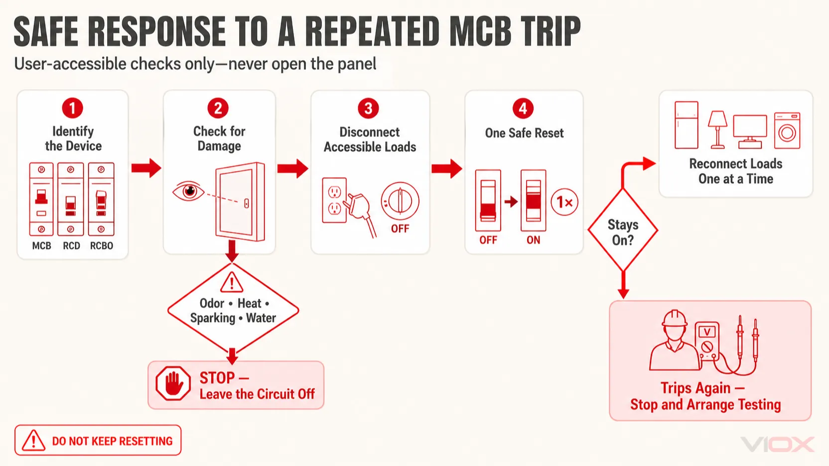
    Safe Checks Before One Reset Attempt

    These checks are limited to normal user-accessible controls and plug-connected loads. Do not remove covers, access terminals, use improvised test equipment, or work on exposed energized parts.

    1. Identify the device and affected circuit. Confirm whether the operated device is an MCB, RCCB/RCD, or RCBO.
    2. Look and listen from a safe position. If there is odor, heat, discoloration, crackling, moisture, or damage, stop.
    3. Switch off or unplug accessible loads on the affected circuit. Do not handle damaged plugs, cords, or wet equipment.
    4. Reset only if there are no danger signs and the suspected accessible load has been removed. Many breaker mechanisms must first be moved fully to OFF and then to ON.
    5. Stop if it trips again. Do not repeat the reset to “test” a persistent fault.
    Safe response path for identifying, checking, isolating, and resetting a tripped MCB once

    For the complete mechanical reset procedure and its limitations, use How to Reset a Circuit Breaker.

    What a Qualified Electrician Should Verify

    The correct test sequence depends on the circuit, device, and event pattern. It may include:

    Verification What it can reveal
    Load and startup-current measurement Sustained overload, excessive starting current, stalled equipment, or a current pattern inconsistent with the load data
    Inspection of conductors, terminals, bus connections, and the breaker seat Loose, oxidized, discolored, pitted, or heat-damaged connections and components
    Insulation-resistance and circuit testing Faulted wiring, damaged equipment insulation, or a fault that remains after accessible loads are removed
    Thermal comparison under known load Abnormal heating relative to similar devices and connections operating under comparable conditions
    Review of time-current curves and correction data Whether the MCB rating and characteristic coordinate with operating current, inrush, ambient conditions, conductors, and available fault current
    Breaker trip testing when justified Whether the device operates within the manufacturer’s characteristic under a controlled test method

    Measurements must be interpreted against the exact MCB series, declared standard, installation conditions, and manufacturer data. A generic trip time or temperature taken from another product is not a valid replacement criterion.

    When the MCB Itself May Be Faulty

    An MCB can be damaged, worn, contaminated, incorrectly installed, or thermally affected, but it should not be treated as the first explanation for every repeated trip. Suspect the device more strongly when:

    • verified circuit current and starting current are within the coordinated design limits;
    • wiring and connected equipment pass the required tests;
    • terminals and mounting interfaces are correct and free of damage;
    • ambient and grouping conditions satisfy the product requirements;
    • the breaker shows mechanical damage, discoloration, poor engagement, or abnormal operation;
    • controlled testing places its performance outside the manufacturer’s characteristic.

    There is no universal 25-year, 30-year, or 40-year replacement rule for every MCB. Condition, fault duty, switching history, installation environment, manufacturer instructions, and verified test results matter more than an unsupported age estimate. See How to Know if a Circuit Breaker Is Bad for the separate breaker-condition workflow.

    What Not to Do

    • Do not keep resetting an MCB that trips immediately or repeatedly.
    • Do not hold the handle in the ON position.
    • Do not replace it with a higher current rating to suppress tripping.
    • Do not change the trip curve without verifying inrush, conductor protection, available fault current, and required disconnection behavior.
    • Do not bypass the MCB or substitute wire, foil, or another improvised conductor.
    • Do not open the distribution board or tighten terminals unless you are qualified and the equipment has been placed in a verified safe state.
    • Do not test a suspected faulty appliance on another circuit.
    • Do not assume that an MCB provides the residual-current protection of an RCCB, RCBO, or GFCI.

    Frequently Asked Questions

    Why does my MCB trip after 10 minutes?

    A trip after about 10 minutes often points toward thermal accumulation from sustained current, but the time alone does not prove an overload. Actual load current, previous loading, ambient temperature, adjacent-device heating, connections, and equipment condition must also be checked against the manufacturer’s time-current data.

    Why does an MCB trip immediately when I switch it on?

    The current may be entering the MCB’s instantaneous pickup range. A persistent short circuit is one possibility, but high inrush current, a stalled motor, damaged equipment, incorrect wiring, or an unsuitable protective-device characteristic can produce a similar pattern. Do not keep resetting it.

    Can a faulty MCB keep tripping even when the load is low?

    Yes, but the breaker should be considered suspect only after actual current, connected equipment, wiring, terminals, ambient conditions, and installation compatibility have been checked. Replacing the breaker without finding the cause can leave the real fault in service.

    Will installing a larger MCB stop repeated tripping?

    It may suppress the warning while leaving conductors or equipment inadequately protected. A higher rating is acceptable only after the circuit design, conductor capacity, installation conditions, load, fault current, and applicable rules have been verified.

    Does an MCB trip because of earth leakage?

    A standard MCB does not measure residual current. It may disconnect an earth fault when the resulting overcurrent reaches its thermal or instantaneous threshold, but additional residual-current protection requires an RCCB, RCBO, GFCI, or other appropriate device for the applicable system and market.

    Technical References

    Repeated tripping is resolved by removing or repairing the cause—not by weakening the protective setting. If the circuit cannot be restored after one safe attempt with accessible loads removed, keep it off and arrange qualified testing. For MCB replacement or application evaluation after the fault has been identified, review the VIOX MCB product family or submit the circuit and load requirements for technical selection support.

  • Series and Parallel Circuits: What’s The Difference

    Series and Parallel Circuits: What’s The Difference

    Ever wonder why when one Christmas light burns out, sometimes the whole string goes dark, but other times just that one bulb stops working? This everyday mystery perfectly illustrates the fundamental difference between series and parallel circuits – two basic ways electrical components can be connected that affect how electricity flows through our devices.

    Understanding series vs parallel circuits isn’t just academic knowledge. These concepts determine everything from why your home outlets work independently to how your car’s electrical system operates reliably. Whether you’re a student learning electronics, a DIY enthusiast tackling electrical projects, or simply curious about how electricity works in your daily life, mastering these concepts will give you valuable insight into the electrical world around you.

    In this comprehensive guide, we’ll explore the key differences between series and parallel circuits, examine real-world applications, and provide practical tips for identifying and troubleshooting both types. By the end, you’ll understand not just how these circuits work, but when and why to use each configuration.

    Quick Answer: The Key Difference Between Series and Parallel Circuits

    Difference Between Series and Parallel Circuits

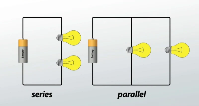
    Series Circuits: Components are connected end-to-end in a single pathway. The same electrical current flows through all components, but the voltage divides across each component based on their resistance.

    Parallel Circuits: Components are connected across common connection points, creating multiple pathways for current. Each component receives the same voltage, but the total current divides between the different branches.

    The Bottom Line: In series circuits, components depend on each other (if one fails, all stop working). In parallel circuits, components operate independently (if one fails, others continue working normally).

    What Are Series Circuits? [Definition and Basics]

    How Series Circuits Work

    A series circuit connects electrical components end-to-end, forming a single continuous path for electric current to flow. Think of it like cars traveling on a single-lane mountain road – every car must follow the same path, and if there’s a roadblock anywhere, all traffic stops.

    In electrical terms, this means:

    • Current flows through each component one after another
    • The same amount of current passes through every component
    • If any component fails or is removed, the entire circuit stops working
    • Components cannot be controlled independently

    Key Characteristics of Series Circuits

    Current Behavior: The most important characteristic of series circuits is that current remains constant throughout the entire circuit. Whether you measure the current before the first component or after the last one, you’ll get the same reading. This happens because there’s only one path for electrons to follow.

    Voltage Distribution: Unlike current, voltage in a series circuit divides across each component. If you have a 12-volt battery powering three identical light bulbs in series, each bulb receives 4 volts. The voltage drops across each component add up to equal the source voltage – a principle that’s crucial for proper circuit design.

    Resistance Effects: In series circuits, total resistance equals the sum of all individual resistances. Adding more components increases the total resistance, which reduces the current flow throughout the entire circuit. This is why adding more lights to a series circuit makes all the lights dimmer.

    All-or-Nothing Operation: Perhaps the most noticeable characteristic is that series circuits operate on an all-or-nothing basis. When you flip the switch, all components turn on together. When one component fails, everything stops working.

    Series Circuit Examples You See Every Day

    Holiday String Lights (Traditional Style): Older Christmas light strings use series circuits. When one bulb burns out, the entire string goes dark because the circuit is broken. Modern holiday lights often include bypass mechanisms or use parallel circuits to avoid this problem.

    Flashlights with Multiple Batteries: Many flashlights stack batteries end-to-end in series to increase the total voltage. Two 1.5-volt AA batteries in series provide 3 volts to power a brighter bulb than a single battery could manage.

    Car Security Systems: Vehicle alarm sensors around doors and windows are often wired in series. If any door or window is opened (breaking the circuit), the alarm detects the open circuit and triggers the warning system.

    Electrical Switches and Fuses: These safety devices are intentionally placed in series with the circuits they protect. When a fuse blows or a switch opens, it breaks the series circuit and stops current flow to prevent damage or provide control.

    What Are Parallel Circuits? [Definition and Basics]

    How Parallel Circuits Work

    A parallel circuit connects components across common connection points, creating multiple pathways for electric current to flow. Imagine a highway with multiple lanes – if one lane is blocked, traffic can still flow through the other lanes. Each lane operates independently.

    In electrical terms, this means:

    • Current has multiple paths to travel
    • Each component operates independently
    • Components can be controlled separately
    • If one component fails, others continue working normally

    Key Characteristics of Parallel Circuits

    Voltage Consistency: The defining feature of parallel circuits is that every component receives the same voltage. Whether you connect one device or ten devices in parallel, each one gets the full source voltage. This is why all the outlets in your home provide the same 120 volts (in the US) regardless of how many appliances you plug in.

    Current Division: While voltage stays constant, current divides between the different branches. Each branch draws only the current it needs based on its resistance. The total current from the source equals the sum of all branch currents – like water flowing through multiple pipes of different sizes.

    Resistance Behavior: Counterintuitively, adding more components in parallel actually decreases the total circuit resistance. This happens because you’re providing more paths for current to flow, making it easier for electricity to complete the circuit. It’s like adding more checkout lanes at a store – more lanes mean less waiting time.

    Independent Operation: Each branch of a parallel circuit operates independently. You can turn devices on and off without affecting others, and if one device fails, the rest continue working normally.

    Parallel Circuit Examples in Your Home

    Household Electrical Outlets: Every outlet in your home is connected in parallel to the main electrical panel. This allows you to plug in appliances independently – turning on your refrigerator doesn’t affect your computer, and if your toaster breaks, your coffee maker still works.

    Automotive Lighting: Your car’s headlights, taillights, and interior lights are wired in parallel. You can control them independently with different switches, and if one bulb burns out, the others continue providing illumination for safety.

    Computer Components: Inside electronic devices, components like memory chips and processors are connected in parallel to ensure they all receive stable voltage for reliable operation.

    Home Lighting Circuits: Modern home lighting uses parallel circuits so you can control different rooms independently. Each light switch controls its own branch without affecting lights in other rooms.

    Series vs Parallel Circuits: Side-by-Side Comparison

    Aspect Series Circuits Parallel Circuits
    Current Flow Same through all components Divides between branches
    Voltage Divides across components Same across all components
    Total Resistance Sum of individual resistances Less than smallest individual resistance
    Component Control All components together Independent component control
    Component Failure Entire circuit fails Other components continue working
    Power Source Load Increases with more components Increases with more components
    Wiring Complexity Simple, fewer connections More complex, more connections
    Cost Generally lower Generally higher
    Reliability Lower (single point failure) Higher (redundant paths)
    Applications Simple controls, voltage division Home wiring, independent devices

    Voltage Behavior: Why It Matters

    In Series Circuits: Voltage drops across each component based on its resistance. This voltage division is useful when you need different voltage levels for different components. For example, if you need to power a 6-volt device from a 12-volt battery, you could add a resistor in series to drop the extra 6 volts.

    In Parallel Circuits: Every component gets the full source voltage, ensuring consistent performance. This is essential for devices that need specific voltages to operate correctly. Your smartphone charger needs exactly the right voltage – too little and it won’t charge, too much and it could be damaged.

    Current Flow Patterns

    Series Current Flow: Current has no choice but to flow through each component in sequence. This makes current measurement simple (same everywhere) but means the weakest component limits the entire circuit’s performance.

    Parallel Current Flow: Current divides based on each branch’s resistance, following the path of least resistance. Low-resistance branches draw more current, while high-resistance branches draw less. This allows devices with different power needs to share the same circuit.

    Resistance Calculations Made Simple

    Series Resistance: Simply add them up

    • Total Resistance = R₁ + R₂ + R₃ + …
    • Example: 10Ω + 20Ω + 30Ω = 60Ω total

    Parallel Resistance: Use the reciprocal formula

    • 1/Total Resistance = 1/R₁ + 1/R₂ + 1/R₃ + …
    • Example: Two 10Ω resistors in parallel = 5Ω total
    • Quick tip: For identical resistors, divide by the number of resistors

    Real-World Applications: Where Each Circuit Type Shines

    Why Series Circuits Are Used

    Voltage Control Applications: Series circuits excel when you need to create specific voltage levels. Battery packs for power tools often connect cells in series to achieve higher voltages – four 3.7V lithium cells in series create a 14.8V battery pack.

    Safety and Control Systems: Series circuits provide excellent fail-safe characteristics. If any sensor in a security system fails (door sensor, window sensor, motion detector), the open circuit immediately alerts the system. This “fail-safe” design ensures problems are detected quickly.

    Cost-Effective Solutions: For simple applications where all components should operate together, series circuits minimize wiring and component costs. A single switch can control multiple lights or devices simultaneously.

    Current Limiting: Series resistors are commonly used to limit current to sensitive components like LEDs, protecting them from damage while ensuring proper operation.

    Why Parallel Circuits Dominate Home Wiring

    Independent Device Control: Parallel wiring allows independent operation of electrical devices. You can run your dishwasher while your computer is off, and neither affects the other’s performance.

    Consistent Device Performance: Every device receives the full line voltage, ensuring optimal performance. Your refrigerator gets the same 120V whether or not you’re running your air conditioner.

    System Reliability: If one device fails, others continue working. When a light bulb burns out, your other lights stay on. This redundancy is crucial for critical systems like emergency lighting and safety equipment.

    Scalability: You can add more devices to parallel circuits without significantly affecting existing devices (within the circuit’s capacity limits). This flexibility makes parallel wiring ideal for expandable systems.

    Series-Parallel Combinations in Complex Systems

    Most real-world electrical systems combine both series and parallel elements to optimize performance, cost, and reliability:

    Automotive Electrical Systems: Cars use series circuits for some controls (like sensor chains) while using parallel circuits for lights and accessories. The starter circuit might have components in series for safety, while the lighting system uses parallel circuits for independent operation.

    Consumer Electronics: Your laptop battery pack might have cells connected in both series (for voltage) and parallel (for capacity). The charging circuit uses series elements for voltage regulation and parallel elements for redundancy.

    Home Electrical Panels: Circuit breakers are in series with their respective circuits (for safety), while individual outlets on each circuit are connected in parallel (for independent operation).

    How to Identify Series vs Parallel Circuits [Practical Guide]

    Visual Identification Methods

    Follow the Current Path: The most reliable method is tracing the path current must take:

    • Series: Only one possible path from positive to negative terminal
    • Parallel: Multiple paths between the same two connection points

    Count Connection Points:

    • Series: Each component connects to exactly two others (except the first and last)
    • Parallel: Components share common connection points, creating “T” or “Y” junctions

    Look for Branching:

    • Series: Components form a single chain
    • Parallel: Current path branches and reconnects

    Switch Behavior:

    • Series: One switch controls all components
    • Parallel: Each branch can have independent switches

    Testing with a Multimeter

    Voltage Testing Method:

    1. Series Identification: Measure voltage across each component. In series circuits, voltages will add up to the source voltage.
    2. Parallel Identification: Measure voltage across each component. In parallel circuits, all components show the same voltage.

    Current Testing Method:

    1. Series Identification: Current measurements will be identical at any point in the circuit.
    2. Parallel Identification: Current measurements will vary between branches but sum to the total current.

    Resistance Testing Method:

    1. Power off the circuit completely
    2. Series: Total resistance equals the sum of individual component resistances
    3. Parallel: Total resistance is less than the smallest individual resistance

    Safety Precautions:

    • Always turn off power before connecting meters for current measurement
    • Use appropriate voltage and current ranges
    • Never measure resistance on powered circuits
    • Double-check connections before applying power

    Common Troubleshooting Scenarios

    When One Component Affects Others (Indicates Series):

    • One bulb burns out, all bulbs go dark
    • One device fails, entire circuit stops working
    • Adding more devices makes all devices dimmer or slower

    When Components Work Independently (Indicates Parallel):

    • Individual devices can be controlled separately
    • One device failure doesn’t affect others
    • Each device maintains consistent performance regardless of others

    Mixed Circuit Identification:

    • Some components work independently (parallel sections)
    • Some components affect each other (series sections)
    • Requires careful analysis of each circuit section

    Advantages and Disadvantages Breakdown

    Series Circuit Pros and Cons

    Advantages:

    • Simplicity: Minimal wiring and connections required
    • Cost-Effective: Fewer components and simpler installation
    • Precise Voltage Control: Easy to create specific voltage drops
    • Uniform Current: Same current through all components simplifies calculations
    • Easy Current Measurement: Current is identical throughout the circuit

    Disadvantages:

    • Single Point of Failure: One component failure stops the entire circuit
    • Voltage Drops: Adding components reduces voltage to each device
    • No Independent Control: Cannot control components separately
    • Limited Flexibility: Difficult to modify or expand
    • Current Limitations: All components must handle the same current

    Parallel Circuit Pros and Cons

    Advantages:

    • Independent Operation: Each device can be controlled separately
    • Reliability: Component failures don’t affect other devices
    • Consistent Voltage: Each device receives full source voltage
    • Expandability: Easy to add more devices (within limits)
    • Flexible Control: Can use individual switches for each branch

    Disadvantages:

    • Complexity: More wiring and connections required
    • Higher Cost: More materials and labor for installation
    • Current Addition: Total current increases with each additional device
    • Load Balancing: Must ensure total current doesn’t exceed source capacity
    • Troubleshooting Complexity: More circuits to diagnose and maintain

    Common Mistakes and Troubleshooting Tips

    Design Mistakes to Avoid

    Voltage and Current Confusion:

    • Mistake: Assuming all components need the same current in parallel circuits
    • Solution: Remember that current divides while voltage stays constant

    Component Rating Oversights:

    • Mistake: Using components rated for different currents in series circuits
    • Solution: Ensure all series components can handle the circuit current

    Safety Circuit Errors:

    • Mistake: Placing safety devices (fuses, breakers) in parallel instead of series
    • Solution: Safety devices must be in series to interrupt current flow

    Power Calculation Errors:

    • Mistake: Underestimating total power consumption in parallel circuits
    • Solution: Calculate power for each branch separately, then sum for total

    Troubleshooting Series Circuit Problems

    Complete Circuit Failure:

    1. Check for open circuits (broken connections, blown fuses)
    2. Test each component individually for continuity
    3. Verify power source voltage and current capacity
    4. Look for corroded or loose connections

    Reduced Performance Issues:

    1. Measure voltage drops across each component
    2. Check for high-resistance connections
    3. Verify component specifications match circuit requirements
    4. Test for temperature-related resistance changes

    Intermittent Operation:

    1. Check for loose connections that make intermittent contact
    2. Test components under varying temperature conditions
    3. Verify switch and connector reliability
    4. Look for vibration-induced connection problems

    Troubleshooting Parallel Circuit Problems

    Individual Branch Failures:

    1. Isolate the problem branch by testing each one separately
    2. Check for open circuits in the failed branch only
    3. Verify branch-specific switches and connections
    4. Test individual component functionality

    Unbalanced Load Issues:

    1. Measure current in each branch to identify imbalances
    2. Check for components drawing excessive current
    3. Verify proper voltage at each branch connection point
    4. Look for resistance differences between parallel paths

    Overloaded Circuit Problems:

    1. Calculate total current draw and compare to source capacity
    2. Check for overheating in wiring and connections
    3. Verify circuit protection devices are properly sized
    4. Consider redistributing loads across multiple circuits

    Which Circuit Type Should You Choose?

    Decision Factors

    Control Requirements:

    • Choose series when all components should operate together
    • Choose parallel when independent control is needed

    Reliability Needs:

    • Choose series for simple, cost-effective applications where simultaneous operation is acceptable
    • Choose parallel for critical applications where component independence is essential

    Voltage Requirements:

    • Choose series when you need to divide voltage or create higher voltages
    • Choose parallel when all components need the same voltage

    Current Considerations:

    • Choose series when current limiting is beneficial
    • Choose parallel when components have different current needs

    Expansion Plans:

    • Choose series for fixed, simple installations
    • Choose parallel for systems that may need future expansion

    Application-Specific Recommendations

    Home DIY Projects:

    • Lighting: Use parallel circuits for room lighting (independent control)
    • Decorative Lights: Series may work for simple applications where simultaneous operation is desired
    • Power Outlets: Always use parallel circuits for outlet installation
    • Switches: Use series switches for safety and control functions

    Automotive Applications:

    • Lighting: Parallel circuits for safety (one bulb failure doesn’t affect others)
    • Sensors: Series circuits for safety systems (any sensor failure triggers alert)
    • Accessories: Parallel circuits for independent operation
    • Charging Systems: Series-parallel combinations for voltage and capacity optimization

    Electronics Prototyping:

    • Power Distribution: Parallel circuits for consistent voltage supply
    • Signal Processing: Series circuits for voltage division and signal conditioning
    • Protection: Series circuits for current limiting and safety
    • Modular Design: Parallel circuits for independent module operation

    Industrial Systems:

    • Safety Circuits: Series circuits for emergency stops and interlocks
    • Power Distribution: Parallel circuits for equipment independence
    • Control Systems: Combination circuits for complex automation needs
    • Monitoring: Series circuits for sensor chains, parallel for independent sensors

    Frequently Asked Questions

    Why don’t we use series circuits for home wiring?

    Home wiring uses parallel circuits for several critical reasons. First, independent operation is essential – you need to turn lights on and off in different rooms without affecting each other. Second, voltage consistency ensures every device gets the full 120V it’s designed for. Third, reliability means that when one device fails, others continue working. Imagine if your entire home went dark every time a single light bulb burned out!

    Can you mix series and parallel in the same circuit?

    Absolutely! Most complex electrical systems use series-parallel combinations. For example, your car might have headlights wired in parallel (for independence) controlled by a switch wired in series (for control). Home circuits use parallel outlets controlled by series-connected circuit breakers. These combinations allow engineers to optimize for both performance and cost.

    Which type uses more power?

    Neither circuit type inherently uses more power – power consumption depends on the components and how they’re used. However, parallel circuits often appear to use more power because each component operates at full voltage and draws its designed current. In series circuits, reduced voltage across each component typically results in lower power consumption per component.

    How do Christmas lights work differently?

    christmas tree lights

    Traditional Christmas lights use series circuits – when one bulb fails, the whole string goes dark. Modern Christmas lights often use parallel circuits or special bypass mechanisms. Some newer strings use a combination: small groups of lights in series, with these groups connected in parallel, providing a balance between cost and reliability.

    What happens to resistance when you add components?

    This is one of the most counterintuitive aspects of circuits:

    • Series circuits: Adding components increases total resistance (like adding obstacles in a single path)
    • Parallel circuits: Adding components decreases total resistance (like adding more paths for current to flow)

    Understanding this concept is crucial for predicting how circuits will behave when modified.

    Conclusion

    Understanding the difference between series and parallel circuits is fundamental to working with electrical systems safely and effectively. Series circuits excel in applications requiring simple control, voltage division, or fail-safe operation, while parallel circuits dominate where independent operation, reliability, and consistent voltage are priorities.

    The key takeaways for practical application:

    • Series circuits connect components end-to-end, sharing current but dividing voltage
    • Parallel circuits connect components across common points, sharing voltage but dividing current
    • Home wiring uses parallel circuits for reliability and independent control
    • Safety systems often use series circuits for fail-safe operation
    • Most real-world systems combine both types for optimal performance

    Whether you’re troubleshooting a circuit, planning a DIY electrical project, or simply trying to understand how your electronic devices work, these fundamental concepts will serve you well. Remember that electrical safety should always be your first priority – when in doubt, consult with qualified professionals.

    Ready to put this knowledge into practice? Start by identifying series and parallel circuits in your own home, and you’ll quickly see how these concepts apply to the electrical systems you use every day.

  • What Is a Contactor? How It Works, Parts, Types & Uses

    What Is a Contactor? How It Works, Parts, Types & Uses

    A contactor is an electrically operated switch used to control motors, heaters, lighting systems, capacitor banks, and other power loads. In a typical normally open contactor, a control signal energizes the coil and closes the main contacts; removing the signal allows them to reopen. This lets a low-power control circuit switch a higher-power load remotely and repeatedly.

    Most industrial contactors discussed in this guide are electromechanical magnetic contactors. In everyday industrial usage, “magnetic contactor” is therefore often shortened to “contactor.” Unlike a circuit breaker, however, a contactor is a control device—not a short-circuit or overload protective device.

    Question Short answer
    What does a contactor do? Switches a power circuit on or off in response to a control signal
    What commonly controls it? Push buttons, thermostats, timers, sensors, relays, or programmable logic controllers (PLCs)
    What loads does it control? Motors, HVAC equipment, heaters, lighting, pumps, compressors, and industrial machinery
    Does it protect against overloads or short circuits? No; protection must be provided by coordinated breakers, fuses, and/or overload relays
    What standard commonly covers industrial electromechanical contactors? IEC 60947-4-1; North American products may also be evaluated to UL 60947-4-1

    How Does a Contactor Work?

    A magnetic contactor converts electrical energy in its coil into mechanical movement. Its operating sequence is simple:

    1. The control circuit energizes the coil. Voltage is applied across coil terminals A1 and A2.
    2. The coil creates a magnetic field. The field attracts the movable armature toward the fixed magnetic core.
    3. The main contacts change state. Normally open main contacts close and supply power to the load. Auxiliary contacts change state at the same time for interlocking, status indication, or control logic.
    4. The coil is de-energized. When the control signal is removed, the magnetic field collapses.
    5. The return spring opens the contactor. The armature returns to its normal position and the main contacts disconnect the load.

    In a typical three-phase motor circuit, incoming power connects to L1, L2, and L3, while the motor side connects to T1, T2, and T3. The exact terminal markings and arrangement must always be confirmed against the device diagram or datasheet.

    Four-step magnetic contactor operation from control signal and coil energization to contact closure and load power.
    Four-step magnetic contactor operation from control signal and coil energization to contact closure and load power.

    A contactor separates the low-power control command from the power circuit feeding the load.

    What Happens When the Contacts Open?

    Opening a circuit under load can create an electrical arc. Contactors use contact geometry and arc-control structures to manage the switching arc within their rated duty.

    Alternating-current (AC) arcs benefit from natural current zero crossings. Direct-current (DC) arcs do not, so a DC contactor may require a different contact arrangement, magnetic arc control, polarity-sensitive connections, or other manufacturer-specific arc-extinction features. An AC contactor should not be assumed suitable for a DC load—or vice versa—based only on its current rating. See the detailed comparison of AC and DC contactors.

    Main Parts of a Contactor

    The exact design varies by product family, but most electromechanical contactors contain the following functional parts.

    Part Function Common identification
    Electromagnetic coil Produces the magnetic field that operates the mechanism A1 and A2
    Fixed core and movable armature Convert magnetic force into mechanical movement Inside the contactor body
    Main power contacts Make and break the load current L1/L2/L3 and T1/T2/T3 on many three-pole devices
    Auxiliary contacts Provide holding, interlocking, signaling, or PLC feedback 13–14 for a typical NO contact; 21–22 for a typical NC contact
    Return spring Returns the mechanism to its normal state when the coil is de-energized Internal
    Arc-control system Helps cool, divide, stretch, or extinguish the switching arc Near the main contacts
    Terminals and enclosure Provide electrical connections, insulation, and mechanical support Product-specific
    Cutaway diagram identifying contactor coil, armature, main contacts, arc chute, auxiliary contact, and common terminals.
    Cutaway diagram identifying contactor coil, armature, main contacts, arc chute, auxiliary contact, and common terminals.

    The coil and armature operate the main contacts; auxiliary contacts report or control the contactor’s state.

    Terminal numbers are useful clues, but they are not a substitute for the manufacturer’s diagram. Auxiliary-contact arrangements, coil type, built-in suppressors, and terminal locations vary. For a deeper component-level explanation, see inside an AC contactor.

    What Is a Contactor Used For?

    Contactors are used when a load must be controlled remotely, automatically, or frequently.

    Motor Control

    In a direct-on-line motor starter, the contactor starts and stops the motor. A circuit breaker or fuse provides short-circuit protection, while an overload relay monitors sustained motor overcurrent and opens the contactor’s control circuit when required.

    This separation of functions is fundamental:

    • Breaker or fuse: short-circuit protection
    • Overload relay: motor overload protection
    • Contactor: normal start-and-stop switching

    HVAC and Pump Systems

    Thermostats, pressure switches, float switches, and building controllers can energize contactor coils to operate compressors, fans, pumps, or electric heating stages. The contactor keeps load current out of the low-power control device.

    Lighting and Heating

    Contactors can switch groups of luminaires or resistance-heating loads from timers, occupancy controls, or energy-management systems. The load type and inrush behavior still matter: a device suitable for a resistive heater is not automatically suitable for a motor or high-inrush lighting load at the same current.

    Industrial Automation

    PLCs and control relays use contactors to switch conveyors, machine tools, ventilation equipment, and other loads. Auxiliary contacts provide electrical interlocking and status feedback, although an auxiliary contact indicates the mechanism’s commanded state and is not always proof that every main pole is electrically healthy.

    Contactor vs Relay vs Circuit Breaker vs Motor Starter

    These devices may appear in the same panel, but they perform different jobs.

    Device Primary job Typical role in a motor circuit Provides overcurrent protection?
    Contactor Frequent remote switching of a load Connects and disconnects motor power No
    Control relay Switches signals or lower-power control circuits Logic, isolation, interlocking, or interface duty No
    Circuit breaker Detects and interrupts overcurrent Protects the feeder or branch circuit against faults Yes, according to its trip functions and ratings
    Motor overload relay Detects sustained motor overload or phase-related abnormalities, depending on type Commands the contactor to open Overload protection, but not normally short-circuit interruption
    Motor starter Combines switching and motor overload functions; may be part of a coordinated assembly Starts, stops, and protects the motor according to the assembly design Depends on the included components
    Functional comparison of a contactor, control relay, circuit breaker, and motor starter.
    Functional comparison of a contactor, control relay, circuit breaker, and motor starter.

    A contactor and a circuit breaker are therefore complementary, not interchangeable. The fuller engineering distinction is covered in contactor vs circuit breaker, while low-power switching differences are explained in contactor vs relay.

    Common Types of Contactors

    AC and DC Contactors

    The load circuit and coil circuit must each be checked independently. A contactor may have an AC-rated power circuit with an AC or DC control coil, depending on its design. DC load interruption usually requires contact structures specifically rated for DC voltage, current, polarity, and time constant.

    IEC and NEMA Contactors

    IEC and NEMA are different rating and selection frameworks, not simple quality grades.

    • IEC contactors are selected closely around application data such as operational current, utilization category, operating voltage, and expected switching duty.
    • NEMA contactors use standardized controller sizes and horsepower-based application tables for common North American motor duties. They are often physically larger than IEC products selected for a comparable application.

    IEC contactors are not generally assigned a universal A/B/C size sequence. Always use the manufacturer’s rating tables rather than trying to convert enclosure dimensions or frame letters into switching capability.

    Modular Contactors

    Modular contactors are DIN-rail devices commonly used in building installations for lighting, heating, ventilation, and similar loads. They are not automatically interchangeable with industrial motor contactors. Compare their application standard, utilization category, switching frequency, coil duty, and load characteristics. See modular contactor vs traditional AC contactor.

    Application-Specific Contactors

    Some applications require contactors designed and rated for a particular switching challenge, including capacitor banks, reversing motor circuits, lighting loads, safety-related control systems, and medium-voltage vacuum switching. A general-purpose current rating alone is not enough to approve a device for these duties.

    How to Select a Contactor

    Start with the application, not with the largest ampere value printed on the front label.

    Selection input What to verify
    Load type Motor, resistance heating, lighting, capacitor bank, transformer, or another load
    Utilization category The category that represents the actual making and breaking duty
    Operational voltage and current Manufacturer rating at the required voltage and utilization category
    Motor data Rated power/current, starting method, starting frequency, and jogging or reversing duty
    Coil supply AC or DC, nominal voltage, frequency where applicable, and allowable operating range
    Number of poles Conductors that must be switched; follow system and equipment requirements
    Auxiliary contacts Quantity and NO/NC arrangement required for holding, interlocking, or feedback
    Operating duty Switching frequency and required electrical endurance for the actual load
    Coordination Upstream short-circuit protective device and overload protection specified for the assembly
    Installation conditions Ambient temperature, altitude, enclosure, ventilation, pollution, and mounting requirements from the manufacturer

    Manufacturer selection guidance likewise requires the main poles, auxiliary contacts, coil supply, utilization category, operating duty, and installation conditions to be evaluated for the specific application.

    Under IEC practice, utilization categories describe the intended switching duty. Common examples include:

    Category Typical duty
    AC-1 Non-inductive or slightly inductive AC loads, such as resistance heating
    AC-3 Starting squirrel-cage motors and opening the circuit while the motor is running
    AC-4 Starting, plugging, inching, or reversing squirrel-cage motors

    AC-4 is more severe than AC-3 because the contactor may make and break high motor current. The same contactor can therefore have different operational-current ratings under different categories. Read the full guide to AC-1, AC-3, and AC-4 utilization categories before selecting by current alone.

    Standards and Protection Boundaries

    IEC 60947-4-1 covers electromechanical contactors and motor starters intended for applicable low-voltage distribution, motor, and other load circuits. In North America, relevant industrial control products may be evaluated under standards such as UL 60947-4-1, subject to the product and assembly application.

    These standards do not mean that every contactor can safely interrupt a prospective short circuit. A contactor must be applied with the short-circuit protective device, overload device, conductors, and enclosure required by the manufacturer, applicable standard, and local electrical rules. Product certification must be verified for the exact model—not inferred from the product category.

    Basic Contactor Wiring Concept

    A contactor circuit normally has two distinct paths:

    • Power circuit: supply → short-circuit protective device → contactor main contacts → overload relay where required → load
    • Control circuit: control supply → stop/safety/overload contacts → start command or controller → contactor coil

    Coil terminals A1 and A2 must receive the voltage shown on the coil or datasheet. They do not automatically match the power-circuit voltage. Incorrect coil voltage can prevent pull-in, cause chatter, overheat the coil, or damage the device.

    Installation, testing, and maintenance must be performed by qualified personnel under applicable electrical safety procedures.

    Frequently Asked Questions

    Is a magnetic contactor the same as a contactor?

    A magnetic contactor is an electromechanical contactor operated by an electromagnetic coil. Because this is the most common design, “magnetic contactor” and “contactor” are often used interchangeably. Other switching technologies and manually operated devices also exist, so the product description should still be checked.

    What is the difference between a contactor and a relay?

    Both can use an electromagnetic coil, but a contactor is designed for power-load switching and includes features suited to the resulting contact and arc duty. A control relay is generally used for signaling, isolation, and logic circuits. Selection must be based on the manufacturer’s load ratings, not the device name alone.

    Does a contactor protect a motor?

    Not by itself. The contactor switches the motor. A coordinated fuse or circuit breaker provides short-circuit protection, and an overload relay or other motor-protection device provides the required overload functions.

    Why does a contactor have A1 and A2 terminals?

    A1 and A2 identify the two coil connections on many contactors. Applying the specified coil voltage across them operates the contactor. Coil voltage, AC/DC type, polarity requirements, and integrated suppression must be verified from the exact product documentation.

    What do 13–14 and 21–22 mean on a contactor?

    Under common IEC terminal identification, 13–14 denotes a normally open auxiliary contact and 21–22 denotes a normally closed auxiliary contact. Not every device includes both, and the wiring diagram remains authoritative.

    Can I use an AC contactor for DC?

    Only when the manufacturer explicitly provides a suitable DC load rating for the required voltage, current, polarity, and circuit conditions. DC arcs are more difficult to interrupt because there is no natural current zero crossing, so an AC load rating cannot be transferred directly to DC service.

    How can I tell whether a contactor is faulty?

    Symptoms can include failure to pull in, chatter, abnormal noise, overheating, damaged terminals, or contacts that do not open or close correctly. Isolate the circuit and follow an appropriate diagnostic procedure. See the contactor testing guide and contactor troubleshooting guide for separate step-by-step workflows.

    Conclusion

    A contactor is the power-switching element that allows a relatively low-power control signal to operate a higher-power load. Its coil moves the main and auxiliary contacts; the selected utilization category defines the kind of switching duty it can perform.

    The central design rule is equally important: a contactor controls the load, while coordinated breakers, fuses, and overload devices provide protection. Select the contactor from the actual load, utilization category, coil supply, operating duty, and manufacturer coordination data—not from current rating alone.

    For product evaluation, compare application-specific ratings and documentation in the VIOX AC contactor range.

  • How to Replace a Circuit Breaker

    How to Replace a Circuit Breaker

    Replacing a circuit breaker safely means more than installing another device with the same ampere number. First confirm that the breaker—not an overload, short circuit, ground fault, loose termination, or damaged bus—is the likely problem. Then use a breaker approved for the specific panel or distribution board, isolate every supply and backfeed source, verify absence of voltage at every exposed part, install the conductors to the manufacturer’s instructions, and test the circuit after the enclosure is fully reassembled.

    This guide covers a straightforward, like-for-like branch-circuit breaker replacement in de-energized low-voltage equipment. It does not authorize live work, and it is not a procedure for replacing a service/main breaker, molded-case circuit breaker (MCCB), air circuit breaker (ACB), PV/DC breaker, or a breaker connected to damaged busbars. Electrical work rules vary by location; where the work requires a licensed or otherwise qualified person, stop and use one.

    Key Takeaways

    • A breaker that trips may be protecting the circuit correctly. Diagnose the load and wiring before replacing it.
    • The new breaker must match the panel’s approved breaker family and the application’s voltage, current, poles, interrupting capacity, trip function, conductor and terminal requirements.
    • Opening the main disconnect does not automatically prove every part is dead. Alternate sources, control supplies, generators, UPS systems, PV, and line-side terminals may remain energized.
    • Verify de-energization with suitable test equipment at every conductor and part that will be exposed. A non-contact voltage indicator alone is not enough for this decision.
    • Never increase the breaker rating to stop tripping unless the complete circuit has been redesigned and verified for that rating.

    First Decide: Replace the Breaker or Stop?

    Use this decision gate before buying or removing anything.

    Decision flow showing when to diagnose, replace a circuit breaker, or stop because of panel damage
    Observation Correct next action Why
    Breaker tripped once after a known temporary overload Remove the load, inspect the connected equipment, and follow the breaker reset procedure A normal protective trip is not proof of a defective breaker
    Breaker trips again, will not reset with the load disconnected, or trips immediately Keep the circuit off and diagnose the circuit and connected equipment Repetitive reclosing can re-energize a fault
    Breaker handle feels loose, will not latch, shows heat damage, or fails a qualified test Plan a like-for-like replacement after checking the panel and conductor condition These findings can support a breaker-failure diagnosis
    Bus stab, rail, enclosure, insulation, or terminal is burned, pitted, melted, wet, or corroded Stop; repair or replace the affected assembly under a qualified plan A new breaker cannot correct damaged distribution equipment
    Main/service breaker, MCCB, ACB, bolt-on industrial breaker, DC/PV breaker, or unknown source arrangement Stop and use the equipment-specific procedure Isolation, stored energy, mounting, settings, and arc-flash risk can be materially different
    Exact compatible replacement cannot be verified Stop and obtain the panel documentation or manufacturer guidance Physical fit and matching amperage do not establish compatibility

    If the only question is whether the existing device has failed, use the circuit breaker condition guide first. For a breaker that simply needs to be reclosed after a resolved event, use the breaker reset guide. A main-breaker job belongs in the separate main breaker replacement guide.

    What Must Match on the Replacement Breaker?

    “Same amps” is not a complete replacement specification. Record the following information before ordering the new device.

    Item to verify What to match or confirm
    Panel or distribution-board identity Manufacturer, model/catalog number, bus or rail system, and the approved breaker family shown on the assembly label or instructions
    Compatibility status A listed/approved device for the assembly, or a classified replacement explicitly documented for that exact panel where the local product system permits it
    System AC or DC, nominal voltage, frequency for AC, polarity and connection diagram where applicable
    Protective rating Rated current, number of poles, trip curve or trip unit/function, and any required neutral switching
    Short-circuit duty Interrupting rating or breaking capacity appropriate for the available fault current and the assembly rating, including any documented series combination
    Circuit function Standard overcurrent, GFCI/RCD, AFCI/AFDD, combined protection, shunt trip, auxiliary contacts, or other required function
    Conductor connection Permitted conductor material, solid/stranded construction, cross-sectional area or wire range, number of conductors per terminal, strip length and terminal type
    Installation data Mounting method, line/load orientation, terminal torque, accessory compatibility, environmental limits and local code requirements

    For North American panelboards, the enclosure label and manufacturer documentation identify acceptable field-installed units. UL Solutions notes that breakers from different manufacturers or product styles are not automatically interchangeable; a classified breaker is suitable only for the specific panelboards and supply limits in its compatibility documentation. In IEC-based installations, also distinguish household/similar AC MCB applications under IEC 60898-1 from industrial circuit breakers under IEC 60947-2. The applicable standard does not replace the need to follow the assembly and breaker manufacturer’s instructions.

    Do not substitute a larger breaker to prevent nuisance tripping. A higher rating can leave the conductor, terminal, receptacle, appliance, or downstream assembly without the intended overcurrent protection.

    Tools and Information Required

    The exact kit depends on the assembly and local electrical-safety rules. A typical qualified-person setup includes:

    • the exact approved replacement breaker and its installation instructions;
    • the panelboard or distribution-board label, wiring diagram and manufacturer instructions;
    • a properly rated voltage tester or multimeter suitable for the system and environment;
    • lockout/tagout equipment where required by the workplace or installation procedure;
    • insulated hand tools suitable for the task;
    • a calibrated torque screwdriver or torque wrench covering the specified terminal range;
    • required personal protective equipment based on the site’s electrical risk assessment;
    • labels or a camera for documenting conductor position, without relying on a photo as the only wiring authority.

    The tester, leads and accessories must be suitable for the system voltage and measurement category. Inspect them before use and confirm the instrument operates according to its instructions before and after the absence-of-voltage test.

    How to Replace a Circuit Breaker in 10 Steps

    Safe circuit breaker replacement sequence from compatibility matching and isolation through termination, panel closure, and testing

    1. Confirm the fault diagnosis and work scope

    Identify what caused the original trip or failure indication. Disconnect loads and check for overload, short-circuit, ground-fault, insulation, appliance and termination problems as appropriate. If the breaker can be tested safely without power, follow the de-energized breaker testing guide.

    Proceed only when the job is a like-for-like branch-breaker replacement and the panel itself is serviceable. Stop if diagnosis requires energized measurements that are not covered by an approved qualified-person work plan.

    2. Record the existing assembly and breaker data

    Photograph and transcribe the panel label, breaker markings, circuit identification, pole arrangement and conductor termination. Record the information in the compatibility table above. If a label is missing, illegible, modified, or inconsistent with the installed parts, do not infer the replacement from appearance.

    3. Obtain and verify the exact replacement

    Compare the candidate breaker against the panel instructions and the existing application data. Check all poles and functions, not just the front-handle marking. A breaker that snaps onto the bus can still be electrically or mechanically unsuitable.

    For a miniature breaker application, review the relevant VIOX MCB range only after the required specifications are known. Industrial molded-case applications should instead use the MCCB selection path and an equipment-specific procedure.

    4. Shut down loads and identify every energy source

    Turn off or safely shut down connected loads before opening the upstream disconnect. Identify normal supply, generator, UPS, PV, battery, control transformer and any other source that could energize the panel or feed the circuit from the load side. Treat line-side service parts as energized unless an upstream means has isolated and verified them.

    5. De-energize and secure the isolation

    Open the applicable disconnecting means. In a workplace, shared installation or other controlled environment, apply the required lockout/tagout procedure so another person cannot restore power. Turning a breaker handle off is a switching action; it is not by itself proof of an electrically safe work condition.

    6. Remove the cover and verify absence of voltage

    Use the enclosure manufacturer’s safe opening method and control the deadfront or cover so it cannot contact live parts. Then use suitable test equipment to check every circuit element and equipment part that will be exposed, including phase-to-phase, phase-to-neutral and phase-to-ground combinations as applicable.

    Verify the tester’s operation according to its manufacturer’s procedure. Account for backfeed and induced voltage. If any unexpected voltage is present—or if the line side remains exposed and adequate protection cannot be maintained—replace the cover and stop.

    7. Document the conductor position and remove the old breaker

    Confirm the circuit identifier and conductor before disconnecting it. Look for heat discoloration, damaged insulation, loose strands, an incorrect conductor size, corrosion, double tapping not permitted by the terminal, or damage where the breaker engages the bus or rail.

    Release the conductor using the correct tool. Then remove the breaker by the method specified for that assembly; DIN-rail, plug-on, bolt-on and proprietary mounting systems are not interchangeable procedures. Do not pry against or reshape a bus connection.

    8. Inspect the panel connection and prepare the conductor

    Examine the bus stab, DIN rail, mounting points, adjacent devices and conductor. If there is pitting, carbon tracking, melted material, loss of spring pressure, damaged plating, severe corrosion or overheating beyond the breaker itself, stop. The distribution assembly requires evaluation and possibly replacement.

    Prepare the conductor only as allowed by the breaker instructions. Do not cut back, splice, tin, double, or alter a conductor merely to make it fit unless that method is specifically permitted and properly engineered.

    9. Install and terminate the replacement breaker

    Set the new breaker to OFF. Mount it in the approved position and orientation, ensuring full engagement without excessive force. Insert the conductor to the specified depth and terminal arrangement. Tighten it to the manufacturer’s stated torque with a suitable calibrated tool; do not guess, reuse an unrelated torque value, or use “as tight as possible.”

    Check that no bare conductor is exposed beyond what the terminal permits, no insulation is clamped under the terminal, no strands are loose, and the conductor is routed without harmful tension or bend. Recheck the breaker’s line/load and polarity markings where relevant.

    10. Reassemble, energize and verify operation

    Remove tools, temporary barriers and loose hardware. Confirm that every conductor is in its intended terminal and that adjacent devices were not disturbed. Reinstall the deadfront and enclosure cover before restoring power.

    With the replacement breaker still OFF, restore the upstream supply. Observe for abnormal sound, odor, heat, arcing or indication. Then switch on the replacement breaker and reconnect loads in a controlled sequence. Confirm normal voltage, load operation and protective-device status using the site’s approved test method. Update the circuit schedule and maintenance record with the breaker model, rating, torque reference, date and reason for replacement.

    What If the New Breaker Trips?

    Do not assume the replacement is defective and do not install a higher-rated breaker. A new trip can indicate an unresolved overload, short circuit, ground fault, damaged appliance, wiring error, incorrect breaker function, neutral problem, insulation failure or unsuitable trip characteristic.

    Leave the circuit off and investigate the circuit and loads. OSHA guidance permits only limited resetting where no exposure to energized parts occurs and states that a repeatedly tripping circuit must be examined and repaired by a qualified person before re-energization in the workplace context.

    Replacement Acceptance Checklist

    Before returning the circuit to normal service, verify that:

    • the root cause was identified or a documented diagnostic plan remains in place;
    • the breaker is approved for the exact panel or distribution assembly;
    • voltage, current, poles, protective function and AC/DC application match;
    • interrupting capacity and assembly short-circuit limits remain adequate;
    • the conductor type and size are permitted by the terminal;
    • the terminal was tightened to the breaker manufacturer’s specified torque;
    • the bus, rail, insulation and enclosure show no unresolved damage;
    • the deadfront and cover are correctly installed;
    • labels and circuit schedules are accurate;
    • the circuit passed the required functional checks without abnormal heating, sound, smell or repeated tripping.

    Frequently Asked Questions

    Can I replace a circuit breaker myself?

    Only if local law permits it, you are competent for the specific equipment, and the task can be fully de-energized and verified. Removing a panel cover can expose line-side parts that remain energized even when the main breaker is open. If the source arrangement, panel compatibility or safe-work boundary is uncertain, use a licensed or qualified electrician.

    Can I replace a 15 A breaker with a 20 A breaker?

    Not as a remedy for tripping. The breaker protects the complete circuit, including conductors, terminals, receptacles and connected equipment. Increasing the rating requires a verified circuit design and compliance review, not a one-part substitution.

    Does turning off the main breaker make the whole panel safe?

    Not necessarily. Incoming line-side terminals may remain energized, and generators, UPS systems, PV, batteries or control circuits can introduce alternate or backfeed sources. Isolation must be identified and absence of voltage must be tested at every exposed part.

    Can I use another brand if the breaker fits?

    Only when the panel documentation or an applicable classified-compatibility record explicitly permits that exact breaker in that exact panel and under the stated supply limits. Similar shape, pole count and ampere rating are not sufficient evidence.

    Why does a newly installed breaker trip immediately?

    Common causes include a downstream short circuit, ground fault, wiring error, connected equipment fault, incorrect breaker type or an unresolved load problem. Keep the circuit off and diagnose it rather than repeatedly resetting or upsizing the breaker.

    Technical References

  • Industrial Plugs and Sockets: IEC 60309 Types, IP Ratings, Pin Configurations, and Selection Guide

    Industrial Plugs and Sockets: IEC 60309 Types, IP Ratings, Pin Configurations, and Selection Guide

    Industrial plugs and sockets are heavy-duty power connectors designed for machinery, construction sites, factories, workshops, outdoor equipment, generators, and temporary power distribution. Compared with domestic plugs, they are built for higher current, tougher environments, stronger mechanical protection, and clearer voltage identification.

    The most common global system for industrial plugs and sockets is IEC 60309, often called CEE, CEEform, or pin and sleeve connectors. These connectors use standardized current ratings, color codes, clock positions, IP protection levels, and pin configurations to reduce dangerous mismatching.

    To choose the right industrial plug or socket, start with the electrical system: voltage, current, phase, neutral requirement, earth connection, IP rating, installation environment, cable size, and whether an interlocked socket is required.

    Quick Selection Table

    Selection Item What to Check Why It Matters
    Voltage 110V, 230V, 400V, 500V, or project-specific voltage Prevents wrong connection and equipment damage
    Current rating 16A, 32A, 63A, 125A, or higher special ratings Must match load, cable, and protective device
    Pin configuration 2P+E, 3P+E, 3P+N+E Matches single-phase or three-phase wiring
    IP rating IP44, IP54, IP55, IP67, IP69K depending on environment Protects against dust, water, washdown, and outdoor exposure
    Standard / approval IEC 60309 and relevant local requirements Ensures correct compatibility for the target market
    Interlock Required or not required Helps prevent plugging or unplugging under load
    Cable entry Gland size, cable outer diameter, strain relief Prevents cable pullout and water ingress
    Material Plastic, rubber, metal, UV-resistant or chemical-resistant material Determines mechanical strength and environmental durability
    Application Factory, construction, marine, food processing, outdoor, generator Different environments need different protection levels

    What Is an Industrial Socket?

    An industrial socket is a power outlet designed for industrial and commercial equipment rather than household appliances. It is normally used with a matching industrial plug to provide a safer, more robust connection for machinery, tools, temporary power, generators, motors, and outdoor electrical systems.

    Industrial sockets are usually larger and stronger than domestic sockets because they may need to handle:

    • higher current
    • three-phase power
    • outdoor exposure
    • vibration
    • dust and water
    • frequent plugging and unplugging
    • mechanical impact
    • harsh temperatures
    • chemical or oil exposure

    In many applications, the socket is mounted on a wall, machine, distribution box, portable power unit, or interlocked switch socket enclosure.


    IEC 60309 Explained

    IEC 60309 is the international standard family widely used for industrial plugs, socket-outlets, and couplers. It is the basis for many of the blue, red, yellow, and other color-coded industrial connectors used worldwide.

    The standard helps define:

    • rated voltage
    • rated current
    • pin arrangement
    • color coding
    • clock position
    • earthing contact arrangement
    • mechanical interchangeability
    • IP protection options
    • connector construction principles

    In practice, IEC 60309 connectors are popular because they reduce the chance of connecting equipment to the wrong voltage or phase system. The color and pin/keying arrangement help prevent unsafe mismatching.


    Industrial Socket Types

    Industrial sockets can be classified by mounting style, protection level, and switching function.

    Socket Type Typical Use Key Feature
    Wall-mounted industrial socket Factories, workshops, outdoor walls Fixed power outlet for machinery or tools
    Panel-mounted socket Control panels, distribution boxes, generator panels Installed into equipment or enclosure face
    Portable socket / coupler Extension leads, temporary power Connects inline with flexible cable
    Interlocked socket High-current or safety-critical loads Prevents plug removal while energized, depending on design
    Switched socket Local power control Combines socket with switching function
    Waterproof socket Outdoor, marine, food processing Higher IP protection for water and dust

    For permanent industrial wiring, wall-mounted and panel-mounted sockets are common. For temporary power and mobile equipment, portable couplers and connectors are often used.


    Industrial Plug Types

    Industrial plugs are selected to match the socket, cable, current rating, voltage, and environment.

    Common industrial plug types include:

    • straight plugs
    • angled plugs
    • splash-proof plugs
    • watertight plugs
    • phase-reversal plugs for some three-phase systems
    • high-current plugs
    • portable power plugs
    • generator plugs
    • panel inlet plugs

    The plug and socket must match electrically and mechanically. Do not force a plug into a socket that appears similar but has a different voltage, clock position, pin arrangement, or current rating.


    2P+E, 3P+E, and 3P+N+E Meaning

    IEC 60309 pin configuration diagram comparing 2P plus earth, 3P plus earth, and 3P plus neutral plus earth industrial plugs.
    IEC 60309 pin configuration diagram comparing 2P+E, 3P+E, and 3P+N+E industrial plug and socket arrangements.

    Pin configuration is one of the most important parts of industrial plug and socket selection.

    Marking Meaning Typical Use
    2P+E Two poles + Earth Common single-phase industrial connector format, such as line + neutral + earth in many IEC 60309 applications
    3P+E Three phases + Earth Three-phase loads that do not need neutral, such as many motors
    3P+N+E Three phases + Neutral + Earth Three-phase loads that also need neutral

    In IEC 60309 terminology, a common single-phase industrial plug is normally described as 2P+E, not P+N+E. In many real installations, those two poles are line and neutral, but the standardized marking focuses on pole count plus earth.

    For example, a three-phase motor often uses 3P+E because it needs three phase conductors and earth but no neutral. A three-phase distribution load with single-phase auxiliary circuits may need 3P+N+E because neutral is required.

    Do not select a 3P+E connector when the equipment needs neutral. This is a common specification error.


    IEC 60309 Color Coding

    IEC 60309 connectors use colors to indicate voltage range. The exact specification should still be checked on the product label and datasheet.

    Color Common Voltage Range / Use Typical Application
    Yellow 100-130V range Construction site tools, portable equipment in some regions
    Blue 200-250V range Single-phase industrial equipment
    Red 380-480V range Three-phase industrial power
    Black 500V range Special industrial or marine applications
    Green Frequency above normal mains range Higher-frequency systems
    Grey Other voltages or special configurations Project-specific use

    Color alone is not enough. Always check the rated voltage, current, frequency, pin count, and clock position.


    IEC 60309 Clock Position Explained

    IEC 60309 color code and clock position chart for yellow, blue, and red industrial sockets.
    IEC 60309 color-code and clock-position chart for common yellow, blue, and red industrial socket voltage ranges.

    IEC 60309 connectors also use a clock position system. When looking at the socket face, the earth contact position is described like a clock dial. This mechanical keying helps prevent a plug for one voltage or frequency from fitting into the wrong socket.

    The clock position should always be verified against the connector marking and datasheet, but common examples include:

    Common Connector Typical Color Common Clock Position What It Helps Prevent
    100-130V range Yellow Often 4h in many site-power applications Prevents connection to higher-voltage sockets
    200-250V range Blue Often 6h for common 230V single-phase systems Helps identify standard single-phase industrial power
    380-480V range Red Often 6h for common three-phase systems Helps identify common three-phase industrial power
    Special voltage or frequency Varies Project-specific Prevents mismatching special equipment

    The practical lesson is simple: color, pin count, and clock position must match together. A connector may have the same color and current rating but still be incompatible because the keyway or earth contact position is different.


    Current Ratings: 16A, 32A, 63A, and 125A

    The common IEC-style industrial plug and socket current ratings are 16A, 32A, 63A, and 125A. Larger special systems exist, but these four ratings cover many factory, construction, and commercial applications.

    Current Rating Typical Application Selection Note
    16A Portable tools, light machinery, small equipment Common for smaller loads
    32A Medium machinery, workshops, portable distribution Often used for higher portable power
    63A Larger machines, industrial distribution, heavy loads Requires careful cable and protection matching
    125A High-power equipment and distribution Often used with interlocked or robust enclosure systems

    The current rating must match the full circuit design, not only the equipment nameplate. Check cable size, protective device, duty cycle, ambient temperature, and installation method.

    Avoid a fixed rule such as “always choose 25% higher.” In real projects, the correct rating depends on load current, cable capacity, protective coordination, local rules, and manufacturer data.


    IP44 vs IP67 vs IP69K

    IP44 vs IP67 industrial socket protection comparison for splashproof and watertight applications.
    IP44 vs IP67 industrial socket protection comparison for indoor splash resistance, outdoor use, dust protection, and temporary immersion.

    IP rating describes protection against solid objects and water ingress. Industrial plugs and sockets are often selected by environment.

    IP Rating Protection Level Typical Use
    IP44 Splash-protected, basic industrial protection Indoor workshops, protected areas
    IP54 / IP55 Better dust and water protection Semi-exposed or dusty environments
    IP67 Dust-tight and temporary immersion protection Outdoor, wet, marine, and temporary power applications
    IP69K High-pressure, high-temperature washdown protection Food processing, washdown areas, special applications

    An IP67 connector is not automatically the best choice for every application. If the plug is frequently connected and disconnected in a dry indoor workshop, IP44 may be sufficient. If the socket is exposed to rain, washing, dust, or mud, a higher rating may be required.


    Interlocked Industrial Sockets

    An interlocked industrial socket combines a socket with a switch or mechanical/electrical interlock. The purpose is to reduce the risk of plugging or unplugging the connector while the circuit is energized.

    Interlocked industrial socket diagram showing the switch mechanism preventing plug removal under load.
    Interlocked industrial socket diagram showing how the switching mechanism prevents plug removal while the circuit is energized.

    Interlocked sockets are often used for:

    • higher-current industrial loads
    • machinery power connections
    • outdoor distribution boxes
    • generator outlets
    • maintenance power points
    • applications where unplugging under load could create arcing

    The exact function depends on the product design. Some interlocked sockets prevent plug removal until the switch is off. Others prevent switching on until the plug is inserted correctly.

    For safety-critical or high-current systems, an interlocked socket can be a better choice than a basic non-interlocked socket.


    Cable Entry, Cable Glands, and Strain Relief

    A good industrial plug or socket installation depends on the cable entry as much as the connector body.

    Check:

    • cable outer diameter
    • gland thread size
    • sealing ring compatibility
    • strain relief design
    • cable bending space
    • conductor size range
    • terminal type
    • tightening method
    • outdoor UV exposure
    • oil, chemical, or washdown exposure

    Poor cable entry selection can defeat the IP rating. A connector body may be rated IP67, but if the cable gland does not seal the cable jacket correctly, water can enter the enclosure.

    For cable entry protection, see VIOX’s cable gland product category.


    Application Guide

    Application Recommended Focus
    Construction sites Yellow low-voltage systems where required, robust body, IP44/IP67 depending on exposure
    Factories and workshops Red 400V three-phase systems, 16A/32A/63A ratings, durable wall sockets
    Outdoor temporary power IP67 protection, strong cable glands, strain relief, impact resistance
    Marine and offshore Corrosion-resistant materials, high IP rating, UV and salt exposure resistance
    Food processing Smooth surfaces, chemical resistance, washdown rating where required
    Generator connections Correct phase, voltage, current, neutral requirement, interlocked or switched socket where needed
    Agricultural sites Dust, water, impact, and chemical exposure resistance

    The environment often decides the connector type. A dry indoor factory socket and a washdown food-processing socket may have the same voltage and current rating but require very different protection designs.


    Industrial Power Connector Types Beyond IEC 60309

    IEC 60309 pin-and-sleeve connectors cover many industrial applications, but they are not the only industrial connector type.

    Other types may include:

    • high-current single-pole connectors for temporary power
    • cam-type connectors used in event power or generator distribution
    • multi-pin connectors for control and signal applications
    • specialized waterproof connectors
    • heavy-duty rectangular connectors
    • hazardous-area connectors for special environments

    These are different product families. If the application is general industrial power distribution, IEC 60309 is usually the first family to check. If the application involves stage power, generator distribution, control signals, or hazardous areas, another connector family may be more suitable.


    Common Selection Mistakes

    Mistake 1: Choosing by Current Rating Only

    A 32A plug is not enough information. Voltage, pin configuration, IP rating, clock position, cable size, and application environment must also match.

    Mistake 2: Confusing 3P+E with 3P+N+E

    If the equipment needs neutral, a 3P+E connector is not suitable. Check whether the load requires single-phase auxiliary circuits, control power, or neutral-connected loads.

    Mistake 3: Ignoring IP Rating After Installation

    IP protection depends on the complete installation: socket cover, plug engagement, cable gland, sealing ring, cable diameter, and enclosure mounting.

    Mistake 4: Using Indoor Connectors Outdoors

    Outdoor plugs and sockets need suitable water, dust, UV, impact, and temperature protection. A connector that works indoors may fail quickly on a construction site or outdoor power box.

    Mistake 5: Ignoring Interlock Requirements

    For high-current or frequently operated sockets, unplugging under load can create arcing and contact damage. An interlocked socket may be required by project specification or safety practice.

    Mistake 6: Assuming All IEC 60309 Products Fit All Markets

    IEC 60309 gives a common technical framework, but local approval, certification, installation codes, and market requirements still matter. For North American, European, or export projects, check the required local documentation before ordering.


    Buying Checklist for Industrial Plugs and Sockets

    Before requesting a quotation, prepare the following:

    • voltage and frequency
    • single-phase or three-phase system
    • current rating
    • pin configuration, such as 2P+E, 3P+E, or 3P+N+E
    • required IP rating
    • plug, socket, coupler, inlet, or interlocked socket type
    • wall-mounted, panel-mounted, or portable installation
    • cable outer diameter and conductor size
    • required material or chemical resistance
    • indoor, outdoor, marine, food, construction, or factory environment
    • local standard or approval requirement
    • quantity and replacement compatibility

    Clear specifications reduce mismatched parts, wrong pin configurations, and IP rating failures.


    FAQ

    Can I plug a 4-pin 3P+E plug into a 5-pin 3P+N+E socket?

    No. A 3P+E plug and a 3P+N+E socket are different configurations. The 5-pin version includes neutral, while the 4-pin version does not. If the equipment needs neutral, use the correct 3P+N+E connector system.

    Why do IEC 60309 connectors use clock positions?

    Clock positions provide mechanical keying. They help prevent plugs with the wrong voltage, frequency, or system configuration from fitting into incompatible sockets.

    Is 2P+E the same as P+N+E?

    In IEC 60309 terminology, the standard marking is usually 2P+E. In many single-phase systems, the two poles are line and neutral, but the connector designation is based on pole count plus earth.

    What color is a 230V industrial socket?

    In common IEC 60309 practice, blue is used for the 200-250V range, often associated with 230V single-phase applications. Always verify the product marking.

    What color is a 400V industrial socket?

    Red is commonly used for the 380-480V range, often associated with 400V three-phase industrial power.

    What is the difference between IP44 and IP67 industrial sockets?

    IP44 provides splash protection for basic industrial environments. IP67 provides dust-tight protection and temporary immersion protection, making it more suitable for outdoor, wet, or harsh environments.

    When should I use an interlocked industrial socket?

    Use an interlocked socket when the circuit should not be plugged or unplugged under load, especially for higher-current machinery, outdoor distribution, generator outlets, and safety-critical equipment.

    Why do some 63A and 125A industrial connectors have a pilot contact?

    Some higher-current connector systems use a pilot contact for control or interlock functions. A pilot contact can be arranged to make after the main contacts and break before them, helping the system control switching before the main power pins separate. The exact function depends on the connector design and wiring scheme.

    Does IP67 still apply when the plug is unplugged?

    Only if the socket cover, cap, or enclosure design maintains the rating in that condition. IP protection depends on the complete assembly, including whether the connector is plugged in, covered, sealed, and installed with the correct cable gland.

    Are industrial plugs and sockets waterproof?

    Only if they are designed and installed with the correct IP rating. A connector rated IP67, for example, still needs the correct cable gland, sealing ring, and installation method to maintain water protection.


    Conclusion

    Choosing industrial plugs and sockets is not only a matter of matching the current rating. A safe selection must match voltage, current, phase system, pin configuration, IP rating, cable entry, interlock requirement, environment, and applicable standard or local approval.

    For most general industrial power applications, IEC 60309 pin-and-sleeve connectors are the first family to consider. Use the color code and pin configuration as a guide, but always confirm the full product marking and datasheet before installation.

  • A Practical Guide to DC Circuit Breakers for Solar, Battery, and EV Systems

    A Practical Guide to DC Circuit Breakers for Solar, Battery, and EV Systems

    This guide is for professional engineers, system designers, and advanced technicians working with modern DC power systems. It answers critical questions about how to select, install, and maintain the right DC circuit breaker to protect high-value assets like solar panel arrays, battery energy storage systems (BESS), and electric vehicle (EV) charging stations.

    Why Can’t I Use an AC Breaker for a DC Circuit?

    difference-between-ac-breaker-and-dc-circuit

    A common but dangerous mistake is using a standard AC circuit breaker in a DC application to save costs. This should never be done. The fundamental difference lies in how they handle an electrical arc—the dangerous surge of energy that forms when a circuit is interrupted.

    AC Breakers Rely on Zero-Crossing: Alternating Current (AC) naturally reverses direction, hitting zero volts 120 times per second. An AC breaker is designed to open its contacts and wait for this natural “off” moment to safely extinguish the arc.

    DC Breakers Must Fight the Arc: Direct Current (DC) flows continuously without a zero-crossing point. A DC breaker can’t wait for the power to stop; it must actively and forcefully kill the arc. This requires a more robust and complex design, often including specialized components like magnetic blowout coils and arc chutes.

    Using an AC breaker in a DC system can lead to the breaker melting, failing to stop a fault, and causing a catastrophic fire. DC-rated breakers are specifically engineered for this challenge and are a non-negotiable safety requirement.

    How to Select the Right Type of DC Circuit Breaker

    Choosing the correct DC breaker involves understanding its physical construction, how it detects faults, and its performance characteristics.

    Classification by Physical Size and Strength

    • Miniature Circuit Breakers (DC MCB): Best for protecting individual, lower-power circuits.
    • Use Cases: Protecting a single string of solar panels, DC lighting circuits, or control panels in telecommunications.
    • Ratings: Typically up to 125A.
    • Molded Case Circuit Breakers (DC MCCB): Larger and more robust, used for protecting main circuits or equipment feeders.
    • Use Cases: Main protection for a large residential solar array, a commercial battery storage system, or industrial machinery.
    • Ratings: 15A to 2500A, often with adjustable trip settings for better system coordination.
    • Low-Voltage Power/Air Circuit Breakers (ACB): The largest class of breakers, designed for main switchgear in major installations.
    • Use Cases: Main incoming protection for a utility-scale solar farm, a large data center, or an entire industrial facility.
    • Ratings: 800A to over 6300A, with advanced electronic trip units and communication features.

    What is a Trip Curve and Which One Do I Need?

    A trip curve defines how sensitive a breaker is to overcurrents. Choosing the right one prevents nuisance tripping while ensuring protection. The most common types defined by the IEC are:

    MCB Type Trip Current (Magnetic) Best For Common Applications
    Type B 3 to 5 times rated current (In) Circuits with low or no inrush current. Resistive loads, residential lighting.
    Type C 5 to 10 times rated current (In) Circuits with moderate inrush current. General purpose loads, commercial lighting, motors. This is the most common, versatile choice.
    Type D 10 to 20 times rated current (In) Circuits with very high inrush current. Large motors, transformers, welding equipment.
    Type Z 2 to 3 times rated current (In) Protecting highly sensitive devices from low-level short circuits. Semiconductor protection, sensitive electronic circuits.

    Critical Sizing Calculations for Real-World Applications

    How to Size a Breaker for a Solar PV System

    Solar PV System

    Sizing overcurrent protection for solar panels is governed by the National Electrical Code (NEC). The key is the “1.56 Rule,” which accounts for continuous operation and potential power surges.

    Here’s how to calculate the breaker size for a PV source circuit:

    1. Find the panel’s Short Circuit Current (Isc) from its datasheet.
    2. Multiply the Isc by 1.56. This factor combines two NEC requirements: a 1.25 multiplier for continuous duty and another 1.25 multiplier for the “edge-of-cloud” effect, a predictable current spike.
    3. Calculation: Required OCPD Rating = Isc × 1.25 × 1.25 = Isc × 1.56
    4. Round up to the next standard breaker size. For example, if your calculation yields 14.23A, you must select a 15A breaker.
    5. Verify Voltage: Calculate the maximum system voltage by multiplying the panel’s Open Circuit Voltage (Voc) by the number of panels in the string and applying a temperature correction factor from NEC Table 690.7. The breaker’s voltage rating must be higher than this calculated value.

    Why Do I Need a Non-Polarized Breaker for a Battery System?

    Battery Energy Storage Systems (BESS) are bidirectional, meaning current flows out during discharge and in during charging. This makes the choice of breaker critical.

    Polarized Breakers: These breakers use permanent magnets and work only when current flows in one direction (from the “+” to the “-” terminal). If used in a BESS, current would flow backward during the charge cycle, causing the arc-quenching mechanism to fail, leading to certain destruction during a fault.

    Non-Polarized Breakers: These are mandatory for any bidirectional application. They are engineered to extinguish an arc safely regardless of the direction of current flow. For any BESS or battery-based system, you must specify a non-polarized DC breaker.

    Navigating Safety Standards: UL 489 vs. UL 1077

    In North America, a critical distinction for safety and code compliance is between UL 489 and UL 1077 certified devices.

    Feature UL 489 – Branch Circuit Breaker UL 1077 – Supplementary Protector
    Purpose Primary Protection: Protects the building’s wiring. It’s the main line of defense. Supplementary Protection: Protects specific components inside a piece of equipment.
    Application Can be installed in a panelboard as the final overcurrent device. Must be used downstream of a UL 489 breaker. It cannot protect building wiring directly.
    The Rule A UL 489 device can be used for supplementary protection. A UL 1077 device can NEVER be used for branch circuit protection. Using it this way is a major safety violation.

    Troubleshooting Common DC Breaker Problems

    Symptom Most Likely Cause How to Fix It
    Nuisance Tripping Inrush Current: A motor or power supply is drawing a large initial current. Change to a breaker with a less sensitive trip curve (e.g., from Type C to Type D).
    Breaker Won’t Reset (Trips Immediately) Persistent Short Circuit: There is a dangerous, active fault on the circuit. Unplug all loads. If it still trips, the fault is in the wiring and requires an electrician. If it holds, plug in devices one by one to find the faulty appliance.
    Breaker Won’t Reset (Handle feels spongy) Needs to Cool Down: The thermal element is still hot from a previous overload trip. Wait 2-3 minutes before attempting to reset. If it still won’t latch, the breaker mechanism is faulty and must be replaced.
    Breaker is Hot Loose Connection: This is the #1 cause of breaker overheating and is a serious fire hazard. DE-ENERGIZE THE CIRCUIT. Use a calibrated torque wrench to tighten the line and load terminals to the manufacturer’s specified torque value.

    Future Trends and Leading Manufacturers

    The market is rapidly evolving beyond traditional breakers to meet the demands of high-power DC systems.

    Hybrid Breakers: These combine the efficiency of a mechanical switch with the arc-free, ultra-fast interruption of a solid-state device. They are becoming the standard for protecting grid-scale battery systems and HVDC infrastructure. Reputable manufacturers like ABB are pioneers in this space with their Gerapid line.

    Smart Breakers: The integration of IoT technology allows breakers to provide data on energy use and predict failures. Industry leaders such as Schneider Electric (with their PowerPact and Acti9 series), Eaton (with their PVGard and Series G lines), and Siemens (with the SENTRON family) offer advanced solutions with communication capabilities for intelligent energy management.

    Related

    What is a DC Circuit Breaker

    Top 10 MCB Manufacturers Dominating the Global Market in 2025

    Quality Assurance in MCB Manufacturing: Complete Guide | IEC Standards 

  • Do Surge Protectors Protect Against Lightning?

    Do Surge Protectors Protect Against Lightning?

    Yes—but only within a defined part of the lightning-protection system. A surge protective device (SPD) can limit a lightning-related transient that reaches equipment through power, data, telecom, antenna, or control conductors. A suitable Type 1 SPD can discharge specified partial lightning current at an installation boundary. However, an SPD cannot intercept a strike, provide a building’s down-conductor path, or replace an external lightning protection system (LPS).

    The useful question is therefore not simply “Can an SPD stop lightning?” It is: How can the lightning event enter the installation, which protection layer meets that path, and what residual stress can the connected equipment withstand? If the device terminology is unfamiliar, start with what an SPD is and which ratings describe it.

    The Short Answer by Lightning Path

    Event path What reaches the electrical system What an SPD can do What an SPD cannot do Protection to verify
    Nearby lightning strike Induced transient voltage in power, signal, or control wiring Limit the transient at a protected conductor boundary Prevent the lightning discharge itself Coordinated power and signal SPDs, bonding, short connections
    Lightning strike to an incoming overhead service or connected line Conducted surge current and overvoltage A correctly selected service-entry device can divert specified surge current and limit voltage Guarantee that every connected device survives Service-entry protection, downstream coordination, all conductive service paths
    Lightning strike to a protected building Lightning current flows through the LPS and creates conducted, induced, and potential-difference effects Type 1 SPDs can be part of the equipotential bonding and internal protection measures Intercept the strike or carry structural lightning current in place of air terminals and down conductors External LPS, bonding, earthing, Type 1 SPDs, downstream SPDs, separation measures
    Utility or equipment switching event Non-lightning transient on the power system Limit the transient when the SPD ratings and installation match the circuit Correct a sustained overvoltage, undervoltage, outage, or overcurrent fault Correct SPD voltage rating, TOV behavior, overcurrent protection, equipment immunity

    Four event paths that determine whether a surge protector can limit lightning-related transients

    This distinction matters because the phrase “direct lightning strike” can refer to different physical situations. A strike to the structure, a strike to an incoming line, and lightning current entering an installation through bonded services are not the same event. They do not place the same duty on one panel-mounted device.

    Type 1 Lightning-Current Duty Is Not Structural Strike Protection

    IEC terminology can be misunderstood here. IEC 61643-11:2025 covers low-voltage AC SPDs for protection against indirect and direct effects of lightning or other transient overvoltages. A Type 1 SPD is tested with an impulse current, commonly identified by the 10/350 μs waveform and the Iimp rating. This allows the device to be specified where partial lightning current may enter low-voltage conductors.

    That product duty does not turn the SPD into a lightning rod or a complete LPS. Structural protection has a different job: manage strike attachment, conduct lightning current toward earth, limit dangerous potential differences, and reduce fire, physical-damage, and touch-voltage risk. IEC 62305-3:2024 covers protection of structures against physical damage and protection of people near an LPS. The related IEC 62305-4:2024 addresses surge protection measures for electrical and electronic systems inside structures.

    Use this practical boundary:

    • An external LPS manages the strike attachment and structural lightning-current path.
    • Bonding and separation measures control dangerous potential differences and flashover risk.
    • Power and signal SPDs limit conducted or induced transient voltage at electrical boundaries.
    • Equipment immunity determines how much residual stress the connected equipment can tolerate.

    Lightning protection chain from external LPS through bonding and SPD to equipment withstand

    For the complete building-level architecture, see the VIOX guide to external LPS, bonding, earthing, and SPDs. This article remains focused on the narrower question of what the SPD itself can do.

    How an SPD Reduces Lightning-Related Stress

    Many low-voltage power SPDs are connected in parallel with the protected circuit. At normal system voltage, their protective components remain non-conductive or highly resistive. When a fast transient raises the voltage beyond the device’s operating region, the SPD conducts surge current through its protection path and limits the voltage appearing across the protected circuit.

    The SPD does not make the transient disappear. Its performance is better understood as a causal chain:

    1. A lightning event couples surge energy into a conductor.
    2. The surge travels toward the installation or equipment.
    3. The SPD changes to a low-impedance state and diverts current.
    4. Voltage is limited to a residual level determined by the device and actual installation.
    5. Downstream wiring and equipment still experience some residual voltage and current.

    This is why “the SPD operated” and “the equipment was guaranteed safe” are not equivalent statements. Lead length, bonding, conductor routing, protection mode, distance between stages, and equipment impulse withstand can all change the voltage that reaches the load. The VIOX guide to common SPD installation mistakes explains how avoidable wiring impedance can undermine an otherwise suitable device.

    Protection Must Cover Every Conductive Entry Path

    A power-panel SPD protects only the conductors and modes included in its installation. It does not automatically protect a device through another incoming path.

    For example, a network switch may connect to:

    • AC power;
    • outdoor Ethernet cable;
    • telephone or coaxial cable;
    • an antenna feed;
    • RS-485, sensor, or alarm wiring;
    • grounded metallic equipment in another building or zone.

    If the AC supply is protected but an outdoor data cable is not, a lightning-related potential difference can still pass through the communication port. Conversely, installing a data-line protector does not replace protection on the AC supply.

    The correct signal protector must match the interface voltage, normal signal level, bandwidth or data rate, shielding and earthing arrangement, connector type, and expected surge environment. Route those decisions to the signal surge protector selection guide rather than using a power SPD as a generic answer.

    Whole-Building and Point-of-Use Protection Have Different Jobs

    A plug-in surge protector is not a substitute for service-entry or distribution-board protection. Its location and test category are intended for a different part of the installation. It may help reduce the residual transient at a sensitive load, but it should not be expected to carry the same duty as an upstream device installed where larger surge current can enter.

    Likewise, installing a high-current SPD at the service entrance does not guarantee an adequately low voltage at every distant or sensitive load. Cable length, branching, oscillation, protection modes, and equipment withstand can justify a downstream SPD. Multiple devices are useful only when their voltage-protection and energy-sharing behavior are compatible.

    The labels Type 1, Type 2, and Type 3 are not a universal recipe. IEC and UL use different classification frameworks, and the correct device depends on its standard, installation point, system voltage, and declared ratings. Use the dedicated Type 1 vs Type 2 vs Type 3 SPD comparison for classification details, then verify the actual combination through the SPD coordination and cascading guide.

    Do Not Choose Lightning Protection by the Largest kA Number

    A higher discharge-current number does not by itself prove better protection for a particular circuit. Before selecting an SPD for lightning-related risk, verify the complete evidence set.

    Evidence to verify Why it matters Common mistake
    Product standard and device type Establishes the applicable test framework and installation role Comparing IEC and UL type labels as if they were identical
    Nominal system voltage and wiring configuration Determines the required protection modes and continuous voltage duty Buying by pole count without confirming L-N, L-PE, N-PE, or DC arrangement
    Uc or MCOV Shows the maximum continuous operating-voltage basis Selecting too close to normal or expected temporary voltage conditions
    Up or VPR Indicates the declared voltage-limiting performance under the applicable test method Looking only at surge-current capacity
    Iimp, In, or other discharge-current rating Describes current duty under a stated waveform and test Comparing peak kA values without comparing waveform and device class
    SCCR and required backup protection Determines compatibility with available fault current and the manufacturer’s protection arrangement Assuming the SPD’s surge rating is its short-circuit rating
    Temporary overvoltage behavior Helps distinguish short transients from longer abnormal system voltage Expecting an SPD to correct a sustained overvoltage
    Connection length, routing, and bonding Affects additional inductive voltage during fast current change Installing the SPD far from the protected bus with long loops
    Status and remote indication Provides evidence that the protection path remains available Treating an installed enclosure as proof that protection is active

    IEC 61643-12:2020 addresses selection, operation, location, and coordination principles for low-voltage AC SPDs. The final choice still has to follow the exact device instructions and the installation rules adopted for the project.

    What to Check After a Suspected Lightning Event

    Do not assume that a breaker trip proves the SPD failed, or that a breaker remaining closed proves the SPD is healthy. The SPD’s internal disconnector, upstream overcurrent protective device, alarm contact, and visual indicator perform different functions.

    After a suspected event:

    1. Treat heat, smoke, odor, cracking, or exposed live parts as an electrical hazard. Isolate the equipment through qualified personnel and follow the site safety procedure.
    2. Record the event and affected circuits. Note which power, data, antenna, or control paths were connected and whether other protective devices operated.
    3. Check the exact SPD status indication. Interpret the window, LED, or remote contact using the manufacturer’s instructions; colors and NO/NC logic are not universal.
    4. Inspect associated protection and connections. Check the specified backup fuse or breaker, terminals, bonding path, and visible signs of overheating or flashover.
    5. Replace or test only within the manufacturer’s permitted method. An intact appearance does not establish remaining protective capacity, and unsafe ad-hoc tests can damage the device or expose personnel.

    Use the SPD status-indicator guide for indicator interpretation. For aging and replacement decisions, use the MOV aging and SPD life guide. There is no defensible universal rule that every SPD must be replaced after the same number of years.

    Standards Boundary: Product, Installation, and Complete System

    Three evidence levels should not be collapsed into one claim:

    • Product evidence: IEC 61643 or UL 1449 evaluation applies to an SPD and its declared scope—not to the performance of an entire building.
    • Installation evidence: Wiring configuration, lead routing, backup protection, bonding, and placement must comply with the applicable installation rules and manufacturer instructions.
    • System evidence: IEC 62305, NFPA 780, or UL 96A addresses the broader lightning-protection system according to the project and jurisdiction.

    The UL Lightning Protection Application Guide describes a complete LPS as a system of strike-termination devices, conductors, grounding electrodes, interconnecting conductors, SPDs, connectors, and fittings. It also directs users to UL Product iQ for the applicable product category and certification limitations. A component marking should therefore be verified against the exact model and intended installation; it is not a blanket system guarantee.

    Final Decision Rule

    A surge protector is necessary in many lightning-protection strategies, but it is not a lightning shield around the building. Judge the protection by the event path and the complete chain:

    strike or coupling point → conductive path → bonding boundary → SPD duty → installed voltage protection → equipment withstand

    If any incoming power or signal path bypasses that chain, the equipment can remain exposed. If a building requires structural lightning protection, engage a qualified LPS designer or installer. For the SPD portion of the project, prepare the system voltage, earthing arrangement, installation position, available fault current, protection modes, applicable standard, upstream and downstream devices, and communication interfaces before comparing the VIOX SPD product range.

    Sources