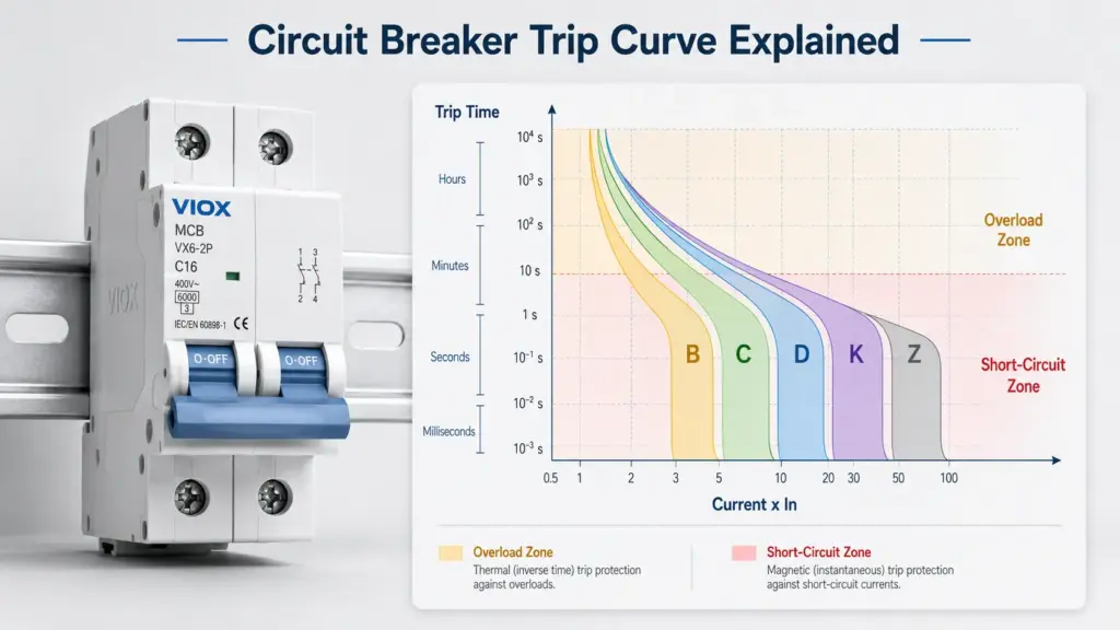
Direct Answer: What Is a Circuit Breaker Trip Curve?
A circuit breaker trip curve, also called a time-current curve or TCC, shows how long a breaker takes to trip at different levels of overcurrent. The horizontal axis usually represents current as a multiple of the breaker’s rated current, while the vertical axis represents trip time. The curve helps engineers choose a breaker that can ride through normal inrush current but still disconnect overloads and short circuits safely.
In simple terms, a trip curve answers this question:
If the current rises above normal, how fast will this breaker open the circuit?
That answer matters for MCBs, MCCBs, RCBOs, motor circuits, transformers, LED lighting groups, control panels, and industrial distribution systems. A breaker that trips too early causes nuisance trips. A breaker that trips too late may fail to protect cables, equipment, or people from fault energy.
Key Takeaways
- A trip curve is a graph of current vs trip time.
- The horizontal axis usually shows current as a multiple of rated current, such as
1 x In,5 x In, or10 x In. - The vertical axis shows the expected operating time, often on a logarithmic scale.
- The lower left area represents overload behavior; the high-current region represents magnetic or instantaneous tripping.
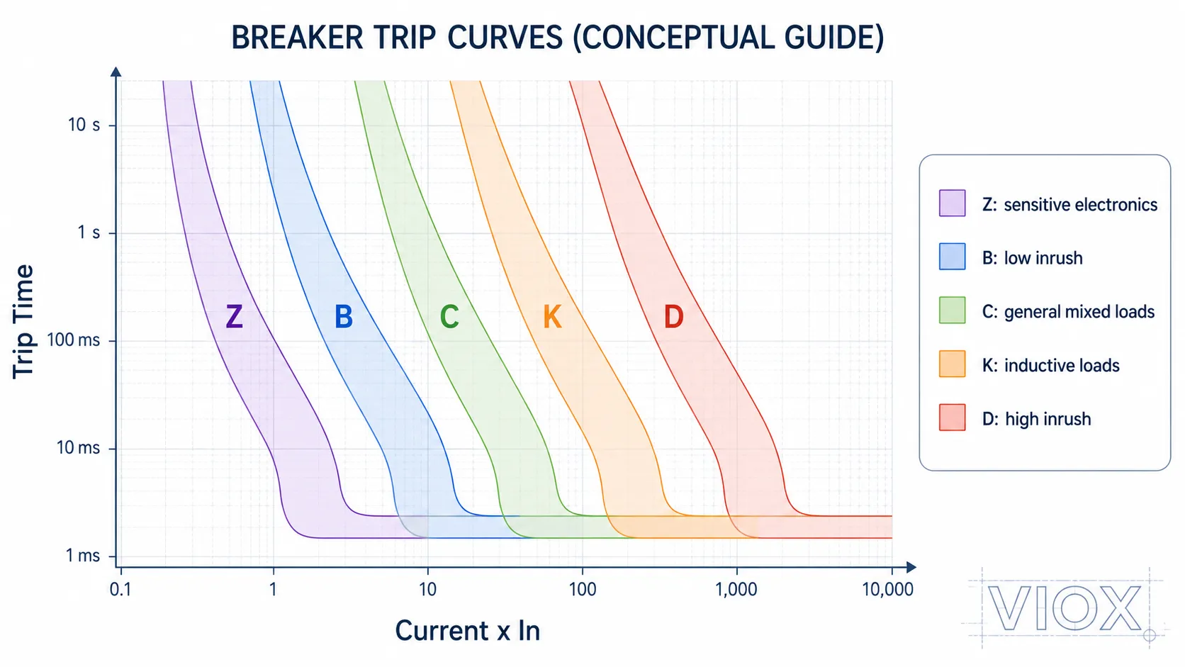
- B, C, D, K, and Z curves describe different instantaneous trip ranges, mainly for miniature circuit breakers and similar devices.
- The curve letter does not change the rated current. A B16, C16, and D16 are all 16A devices; their short-duration trip behavior is different.
- Always check the manufacturer’s actual time-current curve, product standard, breaking capacity, and available fault current before final selection.
Circuit Breaker Trip Curve Chart at a Glance
| Curve Type | Typical Magnetic Trip Range | Inrush Tolerance | Common Application | Main Risk if Misused |
|---|---|---|---|---|
| Z Curve | About 2-3 x In, depending on manufacturer | Very low | Sensitive electronics, semiconductor circuits, control equipment | Nuisance tripping on loads with startup current |
| B Curve | About 3-5 x In | Low | Residential lighting, low-inrush resistive loads, final circuits | May trip during motor, transformer, or LED driver inrush |
| C Curve | About 5-10 x In | Medium | Commercial circuits, small motors, HVAC, LED lighting groups, mixed loads | May trip too slowly if available fault current is low |
| K Curve | Often about 8-12 x In, depending on manufacturer | Medium-high | Motors, inductive loads, control circuits | Less universal; exact behavior must be checked by datasheet |
| D Curve | About 10-20 x In | High | Transformers, welders, large motors, high-inrush industrial loads | Can fail fast disconnection if fault current is not high enough |
These ranges are practical reference values used in many IEC-style discussions. They are not a substitute for the manufacturer’s published curve, installation rules, or project specification. Type K and Type Z especially vary by product family.
For a broader MCB classification guide, see Types of MCB: B, C, D, K, Z Curves, Ratings, Poles, and Applications.
Trip Curve vs Time-Current Curve vs TCC
In circuit protection, these terms are closely related:
| Term | Meaning | Typical Use |
|---|---|---|
| Trip curve | General term for how fast a breaker trips at different currents | Common in MCB and breaker selection |
| Time-current curve | More technical name for the current-vs-time characteristic | Engineering, datasheets, coordination studies |
| TCC | Abbreviation for time-current curve | Protection coordination and selectivity studies |
| Time-current characteristic curve | Formal wording often used in technical documents | Standards, manufacturer documentation |
For most practical breaker selection, trip curve, time-current curve, and TCC refer to the same idea: a graphical relationship between current magnitude and operating time.
How to Read a Time-Current Curve
A time-current curve is usually drawn with logarithmic axes. This can feel confusing at first, but the reading method is simple.
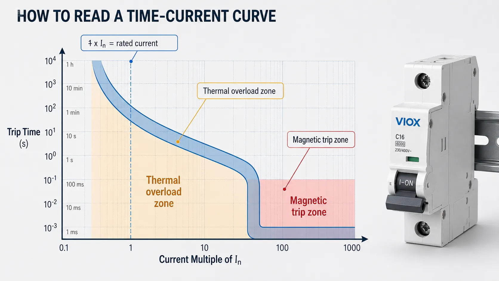
Step 1: Find the Current on the Horizontal Axis
The horizontal axis represents current. In many breaker trip curve charts, current is shown as a multiple of rated current:
1 x Inmeans rated current2 x Inmeans twice rated current5 x Inmeans five times rated current10 x Inmeans ten times rated current
For example, if a breaker is rated 20A, then:
| Multiple of In | Current for 20A Breaker |
|---|---|
| 1 x In | 20A |
| 2 x In | 40A |
| 5 x In | 100A |
| 10 x In | 200A |
This is why two breakers with the same ampere rating can behave differently during startup or fault conditions. Their curve shapes may be different.
Step 2: Find the Trip Time on the Vertical Axis
The vertical axis represents time. It may show seconds, milliseconds, minutes, or a logarithmic time scale. At low overload levels, the breaker may take longer to trip. At high fault current, the breaker may trip much faster.
This is intentional. A breaker should not trip instantly every time a motor starts or a capacitor charges. But it must trip fast enough when the current indicates a real fault.
Step 3: Read the Curve Band, Not a Single Thin Line
Many breaker curves appear as a band rather than one exact line. That band represents manufacturing tolerance, temperature effects, and the allowed operating range of the device.
Do not assume the breaker always trips at one exact second or one exact current. For final design, use the manufacturer’s published curve and the applicable standard.
Step 4: Separate the Thermal and Magnetic Zones
Most low-voltage thermal-magnetic breakers have two main trip behaviors:
| Curve Zone | What It Means | Typical Fault Type |
|---|---|---|
| Thermal overload zone | Delayed tripping caused by sustained overcurrent heating the bimetal element | Overload |
| Magnetic or instantaneous zone | Fast tripping caused by high current operating an electromagnetic mechanism | Short circuit or very high inrush |
The exact curve shape depends on breaker type, frame, trip unit, standard, and manufacturer design.
Thermal Trip Zone: Overload Protection
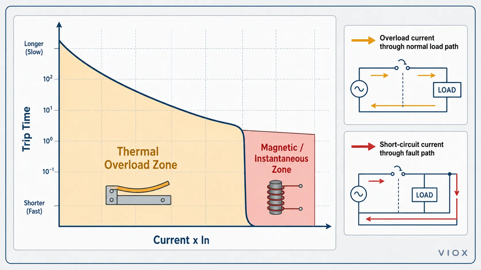
The thermal part of the curve protects against overloads. An overload is current above the allowed value that usually stays in the normal conductive path.
Examples include:
- too many loads on one circuit
- motor running under excessive mechanical load
- cable carrying more current than it should
- heater or equipment drawing more than expected
- poor ventilation causing heat buildup in a panel
Thermal tripping is intentionally delayed. If a load briefly exceeds rated current, the breaker may not trip immediately. If the overload continues long enough to create unsafe heating, the breaker should open.
For a deeper explanation of overload as a fault condition, see What Is a Circuit Overload?.
Magnetic Trip Zone: Short Circuit and High Inrush
The magnetic or instantaneous region responds to high current. This is the part of the curve most closely connected to B, C, D, K, and Z trip types.
High current can come from two very different situations:
- a dangerous short circuit
- a normal but temporary inrush current
The breaker cannot “know” whether the high current is a healthy transformer energizing or a real short circuit. It only sees current and time. The curve must therefore be selected so normal inrush does not cause nuisance tripping, while real fault current still causes fast disconnection.
This is the central tradeoff behind breaker curve selection.
B, C, D, K, and Z Trip Curves Explained
B Curve Breaker
A B curve breaker typically trips magnetically at about 3 to 5 times rated current.
It is usually considered for:
- low-inrush final circuits
- residential lighting
- resistive loads
- general socket or branch circuits where local practice allows
- circuits where available fault current may be limited
The risk is nuisance tripping on motors, transformers, large LED driver groups, and power supplies with high inrush.
C Curve Breaker
A C curve breaker typically trips magnetically at about 5 to 10 times rated current.
It is commonly used for:
- commercial circuits
- mixed loads
- small motors
- HVAC equipment
- LED lighting groups with moderate inrush
- general control panels
C curve is often the practical middle ground, but it still requires enough available fault current for reliable tripping during short-circuit conditions.
D Curve Breaker
A D curve breaker typically trips magnetically at about 10 to 20 times rated current.
It is used for higher-inrush loads such as:
- transformers
- larger motors
- welders
- some industrial machines
- loads with high magnetizing or capacitive inrush
Do not choose D curve only to stop nuisance tripping. If the cable run is long or the fault-loop impedance is high, the available fault current may not be enough for fast magnetic tripping.
K Curve Breaker
K curve breakers are often associated with inductive loads and motor circuits, but the exact behavior depends heavily on the manufacturer and product range. Check the datasheet before using K curve as a direct substitute for C or D curve.
Z Curve Breaker
Z curve breakers are more sensitive and may be used for electronics, measurement circuits, semiconductor-related protection, and low-inrush control applications. They can trip too easily if the load has startup current.
Example: B16 vs C16 vs D16
A common mistake is thinking a C16 breaker is “stronger” than a B16 breaker. That is not the right way to think about it.
A B16, C16, and D16 breaker all have the same nominal rated current: 16A. The difference is their instantaneous magnetic trip threshold.
| Breaker | Rated Current | Typical Magnetic Trip Range | What It Means |
|---|---|---|---|
| B16 | 16A | About 48-80A | Sensitive to high startup current |
| C16 | 16A | About 80-160A | Tolerates moderate inrush |
| D16 | 16A | About 160-320A | Tolerates high inrush but needs high fault current for fast trip |
If a B16 trips when a motor starts, replacing it with C16 may reduce nuisance trips. But before moving to D16, check available fault current, cable length, fault-loop impedance, breaking capacity, and local rules.
For an inrush-focused guide, see MCB B, C, and D Curves Explained.
Circuit Breaker Curve Chart vs Fuse Time-Current Curve
Fuse time-current curves and circuit breaker time-current curves are not always the same shape.
| Point of Comparison | Fuse Time-Current Curve | Circuit Breaker Trip Curve |
|---|---|---|
| Operating principle | Melting element | Thermal-magnetic or electronic trip mechanism |
| Reset after operation | Usually no | Usually yes, after fault correction |
| Current limitation | Can be strong with current-limiting fuse types | Depends on breaker design |
| Curve shape | Depends on fuse class and element design | Depends on breaker trip unit and mechanism |
| Selection focus | Fuse class, voltage, current, I²t, breaking capacity | Curve type, rated current, breaking capacity, coordination |
For more detail on fuse clearing time and breaker response time, see Fuse vs MCB Response Time.
Trip Curve and Breaking Capacity Are Not the Same
Trip curve and breaking capacity are related to protection, but they are not the same rating.
| Term | What It Answers |
|---|---|
| Trip curve | How fast will the breaker trip at a given overcurrent? |
| Rated current | How much current can the device carry under specified conditions? |
| Breaking capacity | What maximum short-circuit current can the device safely interrupt? |
| Voltage rating | At what system voltage can the device interrupt safely? |
A breaker may have the right curve but the wrong breaking capacity. That is unsafe. If the prospective short-circuit current at the installation point exceeds the breaker’s interrupting rating, the breaker may fail during a severe fault.
For MCB applications, see 6kA vs 10kA MCB Breaking Capacity. For industrial breaker rating terms, see Icu vs Ics vs Icw vs Icm Circuit Breaker Ratings.
IEC 60898-1 vs IEC 60947-2: Why the Standard Matters
The same curve letter does not always tell the whole story. Product standard and device family matter.
| Standard Context | Typical Device Scope | Trip Curve Relevance |
|---|---|---|
| IEC 60898-1 | Circuit breakers for household and similar overcurrent protection | Common context for B, C, and D curve MCB discussions |
| IEC 60947-2 | Industrial low-voltage circuit breakers | Industrial breakers may use manufacturer-specific time-current curves and trip unit settings |
| UL 489 | Molded-case and similar circuit breakers for North American applications | North American breaker selection may not use the same B/C/D labeling convention |
Do not assume that every breaker curve chart can be compared directly across standards, brands, or product families. The final reference should always be the manufacturer’s datasheet and the applicable project standard.
For a deeper standards comparison, see IEC 60898-1 vs IEC 60947-2.
How Ambient Temperature Affects Trip Curves
Ambient temperature mainly affects the thermal overload region of a thermal-magnetic breaker curve. The thermal trip element uses a bimetal mechanism, so heat inside the distribution board can influence when the breaker trips under sustained overload.
In practical panel work, nuisance tripping is sometimes blamed on the wrong curve when the real issue is heat:
- breakers installed in tightly packed DIN-rail rows
- high ambient temperature inside an outdoor enclosure
- poor ventilation in a control cabinet
- multiple loaded circuits grouped together
- nearby heat-generating components such as contactors, power supplies, VFDs, or transformers
Higher ambient temperature can make the thermal part of the breaker operate earlier than expected. Lower ambient temperature can delay thermal response. This does not usually change the instantaneous magnetic threshold in the same way, but it can affect how the breaker behaves in the overload zone of the curve.
The correct response is not automatically to move from B curve to C curve or from C curve to D curve. First check the enclosure temperature, grouping, load current, cable size, and the manufacturer’s derating data.
How to Choose the Right Trip Curve
Start with the load and the fault conditions, not just the curve letter.
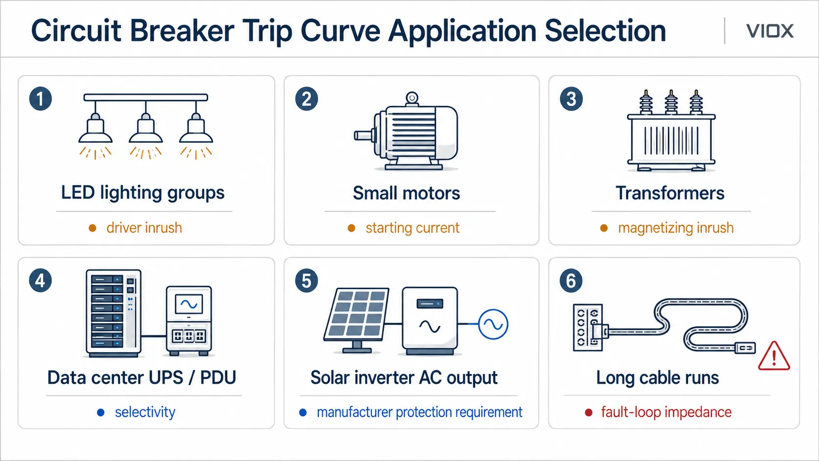
| Application | Common Starting Point | What to Verify |
|---|---|---|
| Low-inrush lighting or resistive loads | B curve | Local wiring rules, cable protection, available fault current |
| Commercial mixed loads | C curve | LED driver inrush, socket loads, fault-loop impedance |
| LED lighting groups | C curve is often considered when inrush is significant | Driver inrush, grouping, switching method, nuisance trip history |
| Small motors and pumps | C curve or motor-specific protection | Starting current, overload protection, short-circuit protection |
| Transformers | D curve or dedicated transformer protection | Magnetizing inrush, available fault current, upstream coordination |
| Data center UPS or PDU circuits | Manufacturer-specific breaker selection | UPS input/output behavior, selectivity, available fault current, coordination |
| Solar inverter AC output | Follow inverter and local grid-side protection requirements | Inverter startup behavior, AC output current, fault contribution, anti-islanding/protection design |
| Sensitive electronics | Z curve where available | Inrush, nuisance tripping, manufacturer guidance |
| Motor and inductive loads | C, D, or K depending on system | Motor starting current, coordination, datasheet curve |
| Long cable runs | Often needs more careful curve verification | Fault-loop impedance, voltage drop, disconnection time, cable thermal withstand |
| RCBO circuits | B, C, or D curve plus residual-current type | Do not confuse trip curve with RCD Type AC/A/F/B |
For RCBO selection, remember that B/C/D is an overcurrent trip curve, while Type AC/A/F/B is a residual-current waveform classification. See RCBO Type AC vs Type A vs Type F vs Type B for the residual-current side.
Common Mistakes When Reading Trip Curves
Mistake 1: Reading the Curve as an Exact Trip Time
A breaker trip curve is usually a band or tolerance zone, not one exact trip point. Ambient temperature, product tolerance, installation conditions, and device design can affect operation.
Mistake 2: Choosing D Curve to Stop Every Nuisance Trip
D curve may reduce nuisance trips, but it also requires higher fault current for fast magnetic operation. If the available fault current is too low, the breaker may not clear faults as expected.
Mistake 3: Confusing Rated Current with Trip Curve
A C20 breaker is not simply “bigger” than a B20 breaker. Both are 20A devices. The curve changes how the breaker responds to short-duration high current.
Mistake 4: Ignoring Cable Protection
The breaker protects the cable as well as the load. Changing the curve or current rating without checking cable size and installation method can create a fire risk.
Mistake 5: Comparing Curves Across Brands Without Datasheets
Two breakers with similar curve letters may not have identical time-current behavior. Manufacturer curves matter, especially for coordination studies.
Mistake 6: Treating MCB Curves and RCD Types as the Same Thing
Type B MCB and Type B RCCB/RCBO do not mean the same thing. One relates to overcurrent trip behavior. The other relates to residual-current waveform detection.
Quick Reading Checklist
Before using a circuit breaker curve chart, check:
- breaker rated current
In - curve type or trip unit setting
- thermal overload region
- magnetic or instantaneous trip region
- current multiple on the horizontal axis
- trip time on the vertical axis
- tolerance band
- rated voltage
- breaking capacity
- product standard
- manufacturer’s datasheet
- available fault current at the installation point
- cable size and installation method
- upstream/downstream coordination
FAQ
What is a circuit breaker trip curve?
A circuit breaker trip curve is a chart showing how long a breaker takes to trip at different current levels. It is also called a time-current curve or TCC.
What does the horizontal axis of a time-current curve represent?
The horizontal axis represents current, often shown as a multiple of the breaker’s rated current. For example, 5 x In means five times rated current.
What does the vertical axis of a time-current curve represent?
The vertical axis represents trip time. It shows how long the breaker may take to operate at a given current level.
What is the difference between B, C, and D curve breakers?
B curve trips magnetically at a lower current range, C curve tolerates more inrush, and D curve tolerates high inrush. Moving from B to C to D generally increases the current required for instantaneous tripping.
Is a trip curve the same as a TCC curve?
In most breaker selection contexts, yes. TCC means time-current curve. It is the technical graph used to show trip time at different current levels.
Are fuse time-current curves and breaker trip curves the same shape?
No. Fuses and breakers operate by different mechanisms, so their time-current curves are not always the same shape. Current-limiting fuses can also behave very differently from thermal-magnetic breakers under high fault current.
Why does a D curve breaker need more fault current?
A D curve breaker has a higher magnetic trip threshold. That helps it ride through high inrush, but it also means the circuit must provide enough fault current for fast tripping during a short circuit.
Can I replace a B curve breaker with a C curve breaker?
Only after checking load inrush, cable size, fault-loop impedance, available fault current, breaking capacity, and local rules. Replacing the curve may solve nuisance tripping, but it can also reduce fault-clearing performance.
What is the best trip curve for motors?
There is no universal answer. Small motors often use C curve in many installations, while higher-inrush loads may require D curve, K curve, MPCB, or a coordinated motor starter design. Motor overload protection must also be considered.
Does trip curve affect breaking capacity?
No. Trip curve describes operating time at different currents. Breaking capacity describes the maximum short-circuit current the device can safely interrupt. Both must be correct.
Conclusion
A circuit breaker trip curve is not just a chart for electricians. It is the link between load behavior, nuisance tripping, overload protection, short-circuit protection, and system coordination.
Use the curve to answer three practical questions:
- Will the breaker tolerate normal inrush current?
- Will it trip quickly enough during a real fault?
- Does the device still have the correct voltage rating, breaking capacity, standard marking, and cable protection?
For VIOX circuit protection selection, start with the application, then choose the correct MCB, RCBO, or MCCB family by rated current, trip curve, breaking capacity, pole configuration, and applicable standard.
