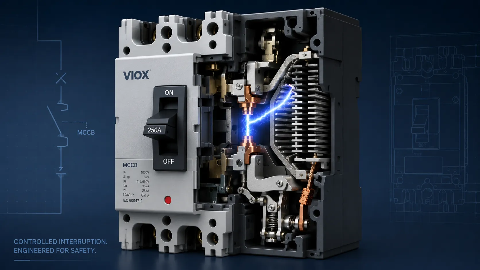
VIOX Electric
Language

Month: July 2025

  • What Is an Arc in a Circuit Breaker? Arc Chute, Arc Runner, and Arc Extinction Explained

    What Is an Arc in a Circuit Breaker? Arc Chute, Arc Runner, and Arc Extinction Explained

    An arc in a circuit breaker is a luminous electrical discharge that forms between separating contacts when the breaker opens a current-carrying circuit. The arc allows current to continue flowing briefly through ionized air or gas until the breaker forces the arc to cool, lengthen, split, and extinguish.

    A circuit breaker does not stop current the instant its contacts separate. It first has to control the arc created during interruption, then extinguish that arc so the circuit can open safely.

    This is why arc control is one of the most important parts of circuit breaker design. A breaker with poor arc extinction can suffer contact erosion, overheating, insulation damage, or failure to interrupt the fault safely.

    Key Arc Terms at a Glance

    Term Meaning Role in a Circuit Breaker
    Arc Conductive luminous discharge across the opening contact gap Allows current to continue briefly after contacts separate
    Arc formation Process where ionized gas forms between contacts Happens during switching or fault interruption
    Arc voltage Voltage across the arc during interruption Helps oppose circuit current and supports extinction
    Arc runner Conductive path that guides the arc away from contacts Moves the arc into the arc chute
    Arc chute Assembly that splits and cools the arc Helps extinguish the arc safely
    Arc splitter plate Metal plate inside the arc chute Divides the arc into smaller arc segments
    Arc extinguishing chamber Space or structure where arc quenching occurs Contains and controls the arc energy
    Arc quenching Process of extinguishing the arc Required for safe interruption

    How Arc Formation Happens in a Circuit Breaker

    Arc formation begins when breaker contacts open while current is still flowing.
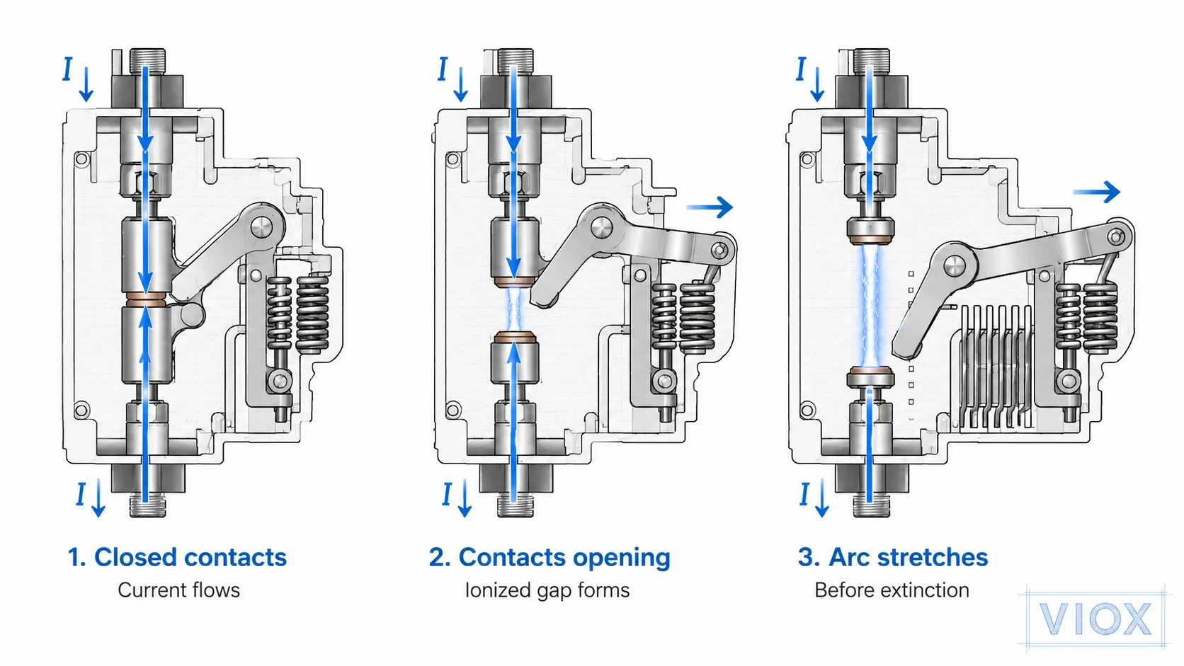
    Circuit breaker arc formation diagram showing contacts opening and ionized arc path.
    Circuit breaker arc formation diagram showing contacts opening, ionized gas, and the temporary arc path during interruption.

    The interruption sequence usually works like this:

    1. The breaker detects an overload, short circuit, or manual switching operation.
    2. The operating mechanism separates the contacts.
    3. Current tries to continue flowing across the small contact gap.
    4. Air or gas between the contacts becomes ionized.
    5. A conductive arc forms.
    6. The breaker drives the arc into the arc-control system.
    7. The arc is lengthened, split, cooled, and extinguished.

    The arc is not a defect by itself. It is a normal physical event during current interruption. The engineering challenge is to control it quickly and safely.


    Why an Arc Forms When Contacts Open

    When contacts are closed, current flows through a metal path. When they begin to separate, the contact area becomes smaller, resistance increases, and heat rises. At the same time, the electric field across the opening gap can ionize the surrounding medium.

    Once the medium becomes conductive, current can continue through the arc plasma even though the metal contacts are no longer touching.

    That is why circuit breakers need more than a simple mechanical switch. They need arc-control structures that can handle the energy released during interruption.


    Main Contacts vs Arcing Contacts

    In larger low-voltage breakers, especially many MCCBs and ACBs, the current path may include main contacts and arcing contacts.

    Contact Type Main Role Why It Matters
    Main contacts Carry current with low resistance during normal operation Designed for conductivity and low heating
    Arcing contacts Take the arc during opening and closing Protect the main contacts from severe arc erosion

    The typical sequence is break-first / make-last for arcing contacts relative to the main contact system, depending on breaker design. During opening, the main contacts separate first so the arc transfers to the arcing contacts. During closing, the arcing contacts make first so the main contacts are not damaged by the initial electrical stress.

    This contact timing is one reason a circuit breaker is more complex than a simple switch. It has to carry current efficiently during normal service and survive repeated interruption events during faults.


    Arc Runner in a Circuit Breaker

    An arc runner is a conductive part that helps move the arc away from the main contacts and toward the arc chute.
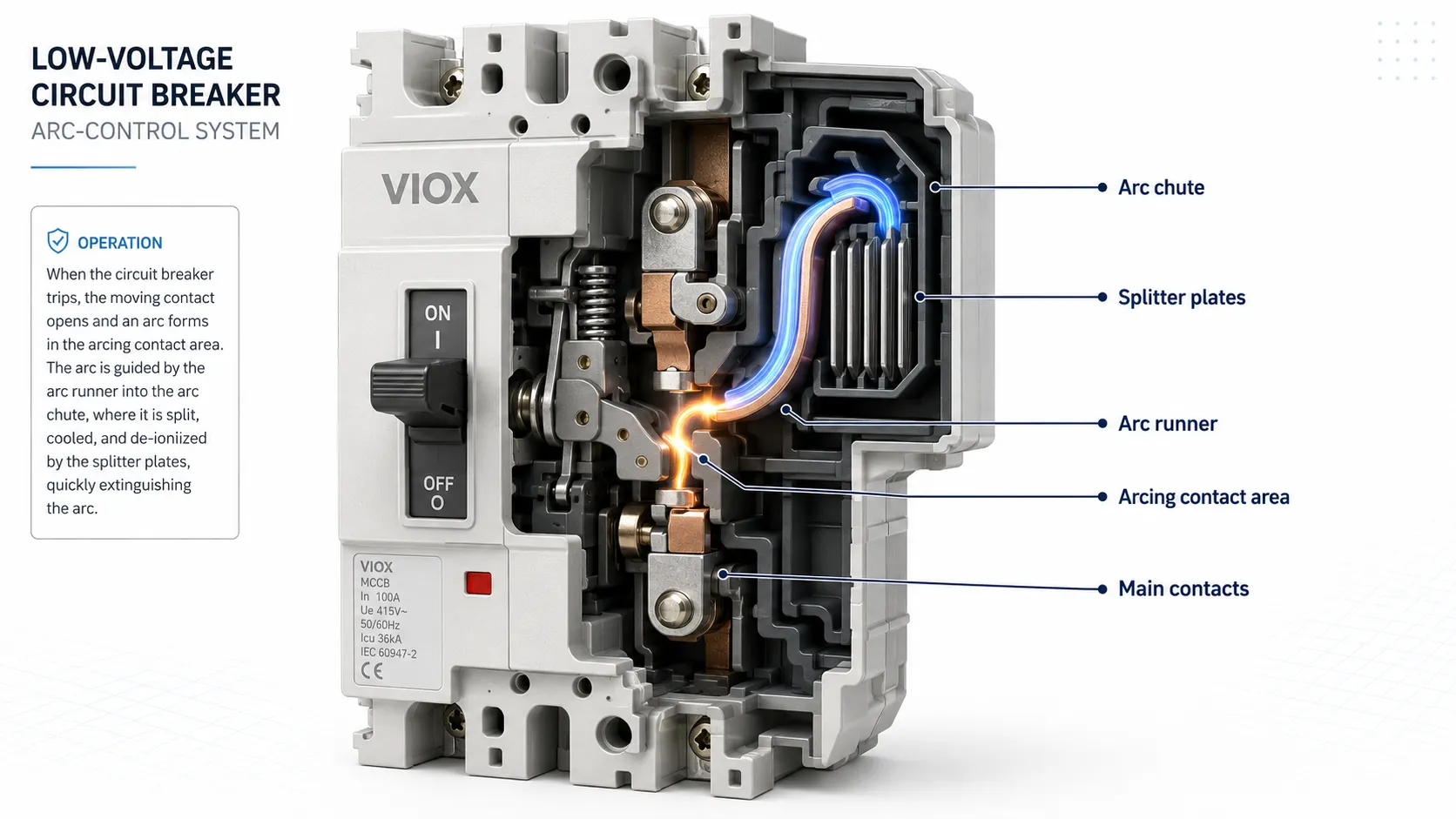
    Arc runner and arc chute inside a circuit breaker guiding the arc into splitter plates.
    Arc runner and arc chute inside a circuit breaker guiding the arc away from the contacts and into splitter plates for cooling and extinction.

    Its function is practical:

    • reduce contact damage;
    • guide the arc into the correct path;
    • help transfer the arc from the contact area to the arc chamber;
    • support faster and more controlled arc extinction.

    In many breaker designs, the arc runner works together with magnetic forces generated by the fault current. A simplified way to express the driving force is $F = I \times L \times B$, where F is the force acting on the arc, I is the arc current, L is the effective arc length in the magnetic field, and B is the magnetic flux density. In practical breaker design, a larger short-circuit current can create stronger magnetic driving force, helping push the arc along the runner into the arc chute where it can be divided and cooled.

    F = I × L × B

    How Magnetic Force Moves the Arc into the Arc Chute

    When high current flows through a breaker, the current path creates a magnetic field. The arc itself also carries current. The interaction between the current-carrying arc and the magnetic field creates a force that can push the arc away from the contacts.

    This magnetic movement is useful because it:

    • pulls the arc away from the contact surface;
    • transfers the arc toward the arc runner;
    • drives the arc into the splitter plates;
    • reduces the time the arc remains on the main contact area.

    In DC breakers, magnetic arc control becomes even more important because there is no natural current zero crossing. This is also why polarity can matter in some DC breaker designs.

    From a product design perspective, the presence of an arc chute alone is not enough. The arc runner shape, contact opening speed, splitter plate alignment, vent path, and insulation material around the chamber all affect whether the arc moves cleanly into the extinguishing zone instead of lingering near the contacts.


    Arc Chute and Arc Extinguishing Chamber

    An arc chute is the structure that helps extinguish the arc after it leaves the contact area. It is often made of multiple splitter plates or arc plates arranged inside an insulating chamber.

    The arc chute works by:

    • lengthening the arc path;
    • splitting one large arc into smaller arc segments;
    • cooling the hot ionized gas;
    • increasing arc voltage;
    • helping de-ionize the arc path;
    • containing hot gases and particles within the breaker design.

    The phrase arc extinguishing chamber usually refers to the space or assembly where this arc control happens.


    Contact Materials: Why Tungsten-Copper and Silver Alloys Are Used

    Circuit breaker contacts must conduct current during normal operation and survive arc heating during interruption. That creates a material tradeoff.

    Common contact material strategies include silver-based alloys for conductivity and arc resistance, and tungsten-copper style materials where stronger arc erosion resistance is needed. The exact material depends on breaker type, current rating, application, and manufacturer design.

    The key engineering idea is this: tungsten provides high melting-point arc erosion resistance, while copper improves conductivity and heat transfer. The goal is to keep the contact structure stable under repeated arc heating while maintaining acceptable contact resistance.

    This is more accurate than saying tungsten-copper is used only to reduce electron emission. In breaker contacts, melting point, erosion resistance, thermal behavior, conductivity, and mechanical integrity all matter.


    What Is Arc Quenching?

    Arc quenching is the process of extinguishing the arc so current stops flowing.

    Circuit breakers may use different arc-quenching methods depending on type and voltage class:

    Breaker Type Common Arc-Quenching Method
    MCB Arc chute with splitter plates
    MCCB Arc chamber, arc runners, splitter plates, molded insulation
    ACB Air arc interruption with larger arc chambers
    DC breaker Arc chute plus magnetic blowout or multi-pole series design
    High-voltage breaker Vacuum, SF6, air blast, or other specialized interruption methods

    For low-voltage MCBs and MCCBs, arc chutes and splitter plates are the most familiar components.


    What Is Arc Voltage?

    Arc voltage is the voltage across the arc during interruption. As the breaker stretches, splits, and cools the arc, arc voltage rises. When arc voltage becomes high enough relative to the circuit conditions, the current can be forced down and the arc can extinguish.

    In practical terms, a good arc-control system increases the arc’s resistance and cooling so the current cannot continue through the ionized path.

    Arc voltage is not one fixed catalog value. It includes voltage drops near the cathode and anode regions, plus the voltage gradient along the arc column. In low-voltage breaker design, the important question is whether the contact geometry, arc runner, splitter stack, gas flow, and chamber insulation can raise arc voltage fast enough under the tested short-circuit condition.

    This is one reason the geometry of contacts, runners, plates, chamber shape, and gas flow matters in breaker design.


    AC Arc vs DC Arc in Circuit Breakers
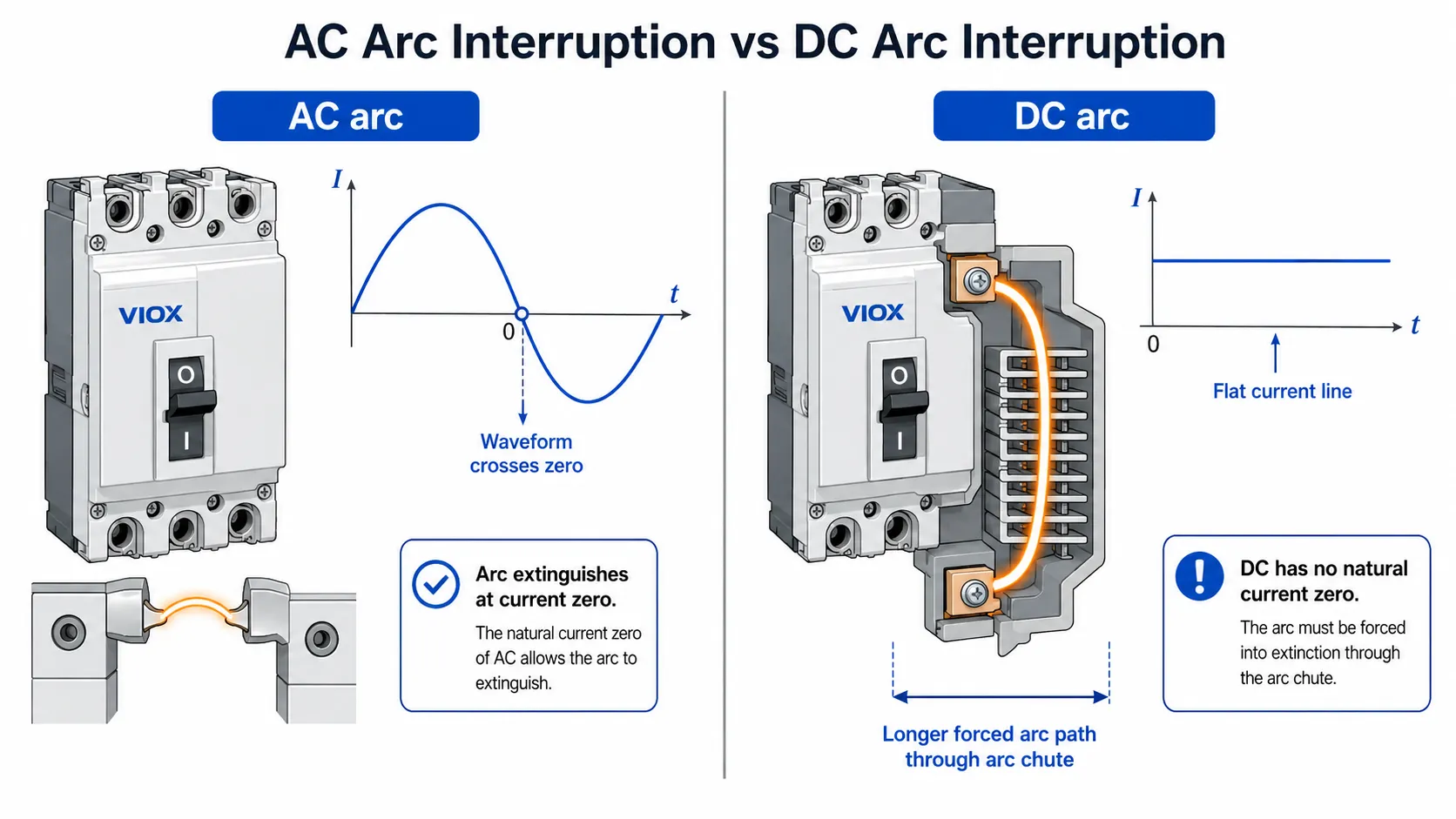
    AC arc versus DC arc comparison showing current zero crossing and forced DC arc extinction by VIOX.
    AC arc versus DC arc comparison showing natural current zero crossing in AC circuits and forced arc extinction in DC breakers.

    AC and DC arcs behave differently.

    Feature AC Arc DC Arc
    Current zero crossing Natural zero crossing every half cycle No natural zero crossing
    Arc extinction Helped by current zero Must be forced by breaker design
    Breaker design AC-rated arc chute may be sufficient for its rating Requires DC-rated arc extinction design
    Polarity concern Usually less critical in low-voltage AC breakers Important in many polarized DC breakers

    This is why an AC breaker should not automatically be used in a DC circuit. DC arcs can persist unless the breaker is specifically designed and rated for DC interruption.

    For DC breaker details, see What Is a DC Circuit Breaker?.


    Arc in MCB vs MCCB vs ACB

    Breaker Type Where Arc Control Happens Practical Difference
    MCB Compact arc chute near the contact system Small space, fast arc splitting, limited frame size
    MCCB Larger molded arc chamber and arc runners Higher frame sizes and stronger interruption structures
    ACB Larger air arc chamber Used in higher-current low-voltage switchgear

    The basic principle is similar: the breaker opens contacts, forms an arc, drives the arc into a chamber, divides and cools it, and interrupts current. The physical size and interruption capability change with breaker type.

    For MCCB internal parts, see MCCB internal structure and components.


    IEC 60947-2, UL 489, and Arc Interruption Ratings
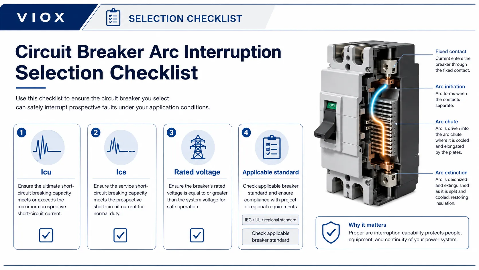
    Circuit breaker arc interruption checklist showing Icu, Ics, rated voltage, and standard selection factors.
    Circuit breaker arc interruption checklist showing Icu, Ics, rated voltage, applicable standard, and breaker selection factors.

    Arc interruption is not evaluated only by visual design. Circuit breakers are tested under standard frameworks that define how interruption performance is verified.

    For low-voltage industrial breakers, IEC 60947-2 is a key standard context. In North American branch and molded-case breaker markets, UL 489 is a key reference. The applicable standard depends on product type, market, and installation.

    Important ratings related to arc interruption include:

    Rating Meaning Why It Relates to Arc Control
    Icu Ultimate short-circuit breaking capacity Verifies the breaker can interrupt a severe fault under defined test conditions
    Ics Service short-circuit breaking capacity Indicates performance after interruption under service-related test conditions
    Icw Short-time withstand current Important for selectivity and withstand behavior in some breaker types
    Rated voltage Voltage at which interruption is tested Higher voltage usually makes arc extinction more demanding

    These ratings should be read from the datasheet and standard context. A breaker with a strong-looking arc chute still needs a tested breaking capacity suitable for the actual circuit.

    For VIOX product selection guidance, the practical question is not whether a breaker has a visible arc chamber. Almost every low-voltage breaker has some form of arc-control structure. The more useful question is whether the contact system, arc runner, splitter stack, molded insulation, vent path, and terminal structure are validated together under the required breaking-capacity test conditions. This is where Icu, Ics, rated voltage, and the applicable standard matter more than visual appearance.


    Arc in a Circuit Breaker vs Arc Fault Circuit Breaker

    The same word “arc” appears in two different breaker topics, but the meanings are different.

    Term Meaning
    Arc in a circuit breaker The internal arc formed when breaker contacts open during interruption
    Arc fault Unwanted arcing in wiring, cords, terminals, or equipment
    Arc fault circuit breaker / AFCI A breaker designed to detect dangerous arc-fault signatures in a circuit

    A normal breaker arc occurs inside the breaker during switching or fault interruption. An arc fault occurs outside the intended contact system and may indicate damaged wiring, loose connections, or insulation failure.


    Signs of Possible Breaker Arcing Problems

    Breaker arcing inside the device is normal during interruption, but abnormal external symptoms should not be ignored.

    Call a qualified electrician or technician if you notice:

    • burning smell near a panel;
    • buzzing, sizzling, or crackling from a breaker;
    • heat damage or discoloration;
    • melted insulation near terminals;
    • repeated breaker tripping;
    • visible flash outside the breaker;
    • loose or damaged terminals.

    Do not open or inspect live breaker internals. Circuit breakers are sealed or assembled safety devices, not field-repairable arc chambers.


    Arc Erosion, Contact Pitting, and When Breaker Arcing Becomes a Problem

    Each interruption event can stress the breaker contacts. In normal service this is expected, but repeated severe faults or poor terminal conditions can accelerate wear.

    Possible signs of excessive arc-related stress include:

    • pitted or eroded contacts in serviceable industrial equipment;
    • discoloration around terminals or vents;
    • unusual smell after operation;
    • breaker case damage;
    • repeated trips under similar load conditions;
    • rising contact resistance in equipment where measurement is part of maintenance practice.

    For sealed miniature breakers, internal contact inspection is usually not practical. For larger serviceable switchgear, inspection and maintenance should follow the manufacturer’s instructions and the site’s safety procedures.


    Common Misunderstandings About Circuit Breaker Arcs

    Mistake 1: Thinking any arc means the breaker is defective

    An internal arc during interruption is normal. The breaker is designed to control it.

    Mistake 2: Thinking an arc chute prevents all breaker damage

    The arc chute reduces and controls arc energy, but repeated high-fault interruptions can still stress contacts and internal parts.

    Mistake 3: Confusing breaker arcing with arc fault protection

    Internal breaker arc control and AFCI arc-fault detection are different topics.

    Mistake 4: Using AC arc assumptions for DC breakers

    DC arcs are harder to extinguish because there is no natural zero crossing. Use DC-rated breakers for DC circuits.

    Mistake 5: Ignoring terminal condition

    Loose terminals can cause external heating and arcing. That is different from the normal internal arc formed during breaker interruption.


    FAQ

    Can an AC arc chute extinguish a DC arc?

    Not automatically. AC interruption benefits from natural current zero crossings, while DC interruption must force the arc to lengthen, cool, and extinguish without that help. A breaker used on DC circuits should be specifically rated for the DC voltage, current, polarity condition, and application.

    What is the difference between arcing contacts and main contacts?

    Main contacts are optimized for low-resistance current carrying during normal operation. Arcing contacts are designed to take the electrical stress during opening and closing, so the main contacts are not exposed to the worst arc erosion.

    How often should arcing contacts be inspected in industrial breakers?

    Follow the breaker manufacturer’s maintenance instructions and the site’s electrical safety procedure. Inspection frequency depends on breaker type, fault history, switching duty, environment, and whether the device is serviceable. Sealed MCBs and many MCCBs are normally replaced rather than opened for contact inspection.

    Why does a breaker smell burnt after tripping?

    A light odor after a severe interruption can come from hot gases and arc byproducts inside the breaker. Persistent burnt smell, discoloration, melted insulation, terminal heating, or repeated tripping is not normal and should be checked before the circuit is re-energized.

    Does a higher Icu rating mean a better arc chute?

    Not by itself. Icu is a tested ultimate short-circuit breaking capacity under defined conditions. Arc chute design matters, but so do contact speed, runner geometry, molded insulation, terminal design, rated voltage, and the complete test sequence. Ics is also important because it indicates service short-circuit performance under the applicable standard.

    Can breaker arcing be repaired?

    For sealed MCBs and many MCCBs, internal arcing damage is not field-repairable. Replace the device if inspection or manufacturer guidance indicates damage. Larger serviceable breakers may have manufacturer-approved maintenance procedures, but repair should only be done by qualified personnel using approved parts and test methods.


    Related VIOX Resources


    Conclusion

    An arc in a circuit breaker is a normal but intense electrical event created when contacts open under current. The breaker must move that arc into an arc-control system, split it, cool it, raise arc voltage, and extinguish it.

    The most important parts to understand are the arc runner, arc chute, arc splitter plates, and arc extinguishing chamber. These components are what allow a circuit breaker to interrupt current safely instead of acting like a simple switch.
  • Why Does the US Use 120V Instead of 220V? The 120/240V System Explained

    Why Does the US Use 120V Instead of 220V? The 120/240V System Explained

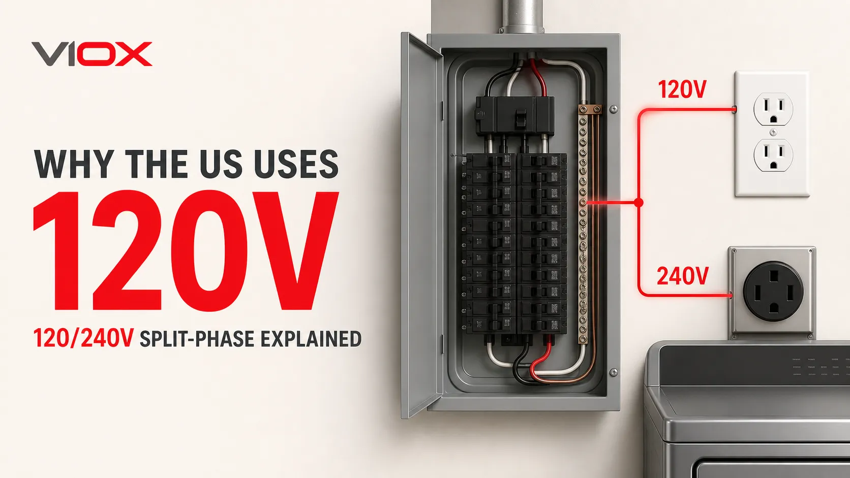
    The short answer is that the United States does not use only 120 volts. Most US homes receive 120/240V split-phase power at 60 Hz. Standard receptacles supply 120V, while electric ranges, clothes dryers, water heaters, air-conditioning equipment, EV chargers, and other high-power loads may use 240V.

    America retained 120V for ordinary outlets because its early electric-lighting systems, appliances, wiring practices, and safety rules developed around the 100–120V range. Once that installed base became enormous, changing every compatible device and branch circuit would have brought high cost with limited practical benefit. The split-phase system already gives US homes access to 240V where the higher voltage is useful.

    US Voltage at a Glance

    Question Short answer
    What is the standard US outlet voltage? Nominally 120V AC at 60 Hz
    Do US homes have 220V or 240V? Yes. Most homes have 240V available between the two hot conductors
    Is the US supply 110V or 120V? 120V is the modern nominal value; 110V and 115V are older or informal terms
    Why are large appliances connected to 240V? For the same power, 240V requires half the current of 120V
    Is a plug adapter also a voltage converter? No. An adapter changes the plug interface, not the voltage or frequency
    Is 240V always better than 120V? No. Each voltage has practical advantages, and system design matters more than the number alone

    The US Department of Energy describes US household power as 110–120V at 60 Hz, compared with 220–240V at 50 Hz in many other countries. For residential service, however, the more complete description is 120/240V split phase.

    How 120/240V Split-Phase Power Works

    A typical North American home is supplied from a center-tapped transformer secondary. The three service conductors are:

    • Hot leg L1
    • Hot leg L2
    • Center-tapped neutral

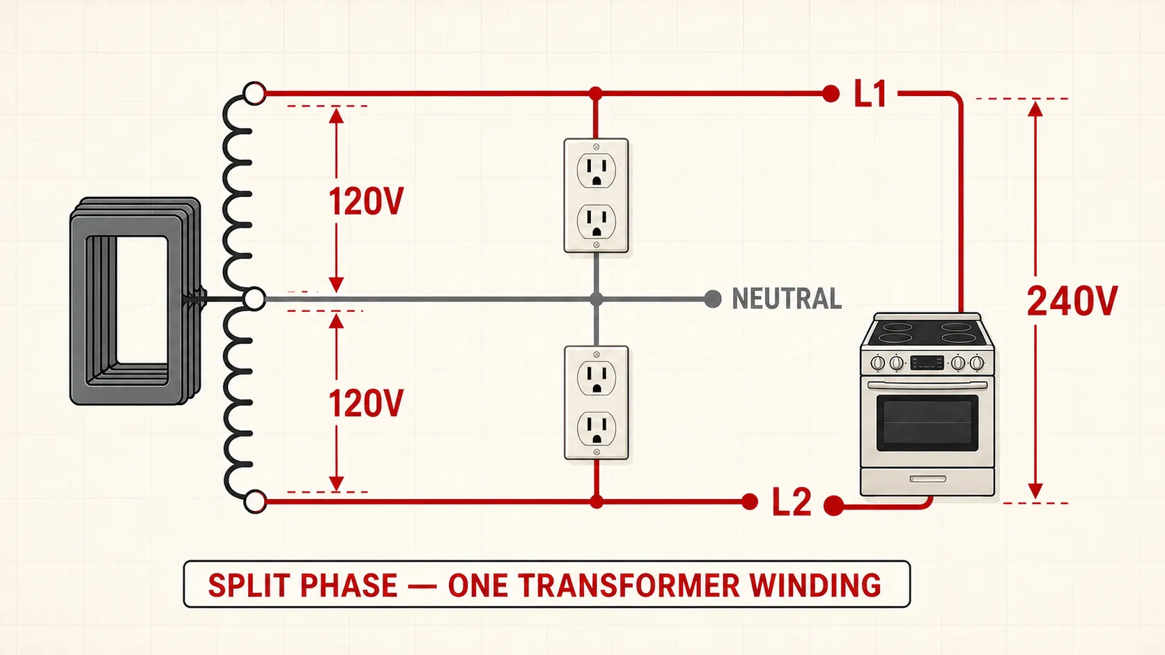
    The voltage from either hot leg to neutral is 120V. The voltage from L1 to L2 is 240V.

    120/240V split-phase transformer diagram showing L1, L2, neutral, two 120V branches, and one 240V load
    North American 120/240V split-phase service uses a center-tapped neutral to supply two 120V legs and one 240V line-to-line connection.
    Connection Nominal voltage Common uses
    L1 to neutral 120V Lighting and standard receptacle circuits
    L2 to neutral 120V Lighting and standard receptacle circuits
    L1 to L2 240V Ranges, dryers, water heaters, HVAC equipment, workshop loads, and EV charging

    This is called split phase, not two-phase power. The two 120V legs come from opposite ends of one transformer winding. When one leg is positive relative to neutral, the other is negative, producing 240V between them.

    US government housing guidance describes most homes as receiving nominal 120/240V single-phase, three-wire service. Commercial buildings may instead use systems such as 120/208V three-phase, so equipment labeled for 240V should not automatically be assumed to perform identically on 208V.

    Why Did the United States Standardize Around 120V?

    There was no single worldwide committee that selected one household voltage. Electrical networks developed locally, and early decisions became embedded in generating equipment, lamps, wiring, and appliances.

    Early lighting systems established the voltage range

    Thomas Edison’s early direct-current lighting systems operated at about 100–110V. The voltage suited the incandescent lamps and distribution technology available at the time. By the late 1880s, 110V lighting systems and compatible equipment were already in commercial use.

    Alternating current later won the wider distribution battle because transformers made it practical to transmit power at high voltage and step it down near users. However, AC suppliers still needed to serve an existing market of lamps and equipment designed around the established utilization voltage. The supply method changed, but the familiar low-voltage range remained.

    The nominal voltage gradually became 120V

    People still say “110V” or “115V,” but the modern nominal US supply is 120V. These numbers are not three entirely different systems. They reflect historical naming, earlier nominal values, equipment ratings, and normal supply variation.

    The same naming issue occurs with “220V,” “230V,” and “240V.” In a modern US residence, 240V is the appropriate nominal line-to-line value. In many countries using IEC-based public supply systems, 230V is the nominal line-to-neutral value. Always use the equipment nameplate and the applicable local supply specification rather than relying on informal voltage names.

    Infrastructure made a nationwide conversion unattractive

    Once millions of buildings, receptacles, lamps, appliances, and protective devices were designed around 120V branch circuits, changing the standard would have required a coordinated replacement program across the entire country.

    More importantly, the US did not need to choose between 120V and 240V. Split-phase service preserved 120V for general-purpose circuits while making 240V available for higher-power equipment. That reduced the potential benefit of a nationwide conversion to 230V outlets.

    120V vs 220–240V: What Changes Electrically?

    For a load drawing real power under the simplified relationship:

    P = V × I

    where:

    • P is power in watts
    • V is voltage in volts
    • I is current in amperes

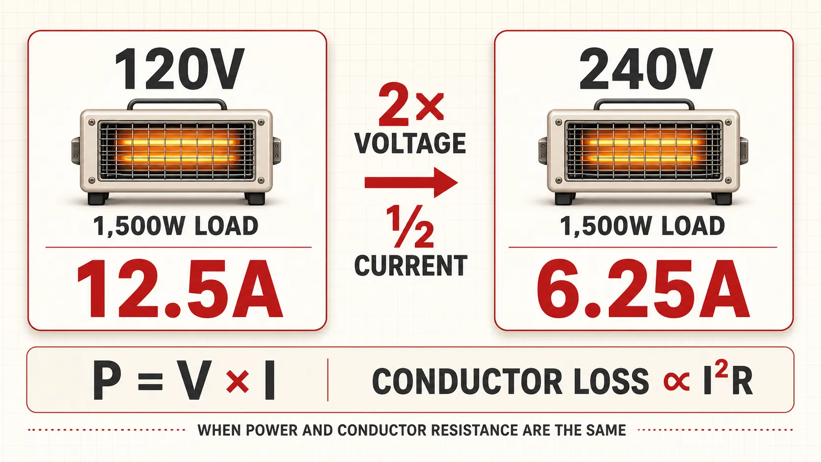
    A 1,500W load would draw approximately:

    • 12.5A at 120V
    • 6.25A at 240V
    Current comparison for the same 1,500W load: 12.5A at 120V and 6.25A at 240V
    For the same 1,500W load, increasing supply voltage from 120V to 240V reduces current from 12.5A to 6.25A.

    Doubling the voltage halves the current for the same power. This matters because resistive conductor loss follows:

    P loss = I²R

    If conductor resistance were unchanged, halving the current would reduce that conductor loss to one quarter. Actual installations also change conductor size, breaker rating, circuit length, connection methods, and permitted load, so this equation should not be turned into a claim that a 240V country automatically uses 75% less household electricity.

    Practical comparison

    Factor 120V circuit 220–240V circuit
    Current for the same power Higher Lower
    Conductor loss with the same resistance and power Higher because current is higher Lower because current is lower
    Power available at the same current rating Lower Higher
    Typical US use Lighting, receptacles, small appliances High-power appliances and dedicated equipment
    Shock exposure Lower voltage, but still hazardous Higher voltage can drive more current through the body
    Appliance compatibility Requires equipment rated for the available supply Requires equipment rated for the available supply

    For a deeper engineering treatment, see VIOX’s guide to voltage, current, and line-loss calculations or use the voltage drop calculator for a defined circuit.

    Is 240V More Efficient Than 120V?

    Higher voltage can deliver the same power at lower current, which can reduce voltage drop and conductor losses. That is why power grids transmit electricity at voltages far above either household utilization voltage, then step it down closer to the load.

    But appliance energy consumption depends on the appliance design and its power rating, not voltage alone. A 1,500W heater designed for 120V and a 1,500W heater designed for 230V both consume about 1,500W while operating. Their required current differs, but the useful heat output is broadly tied to power.

    Some 230V appliances appear faster because the local socket circuit permits a higher-power appliance. For example, a higher-wattage kettle can heat water faster than a lower-wattage kettle. The faster result comes from the higher permitted power, not from voltage acting as a universal speed multiplier.

    Is 120V Safer Than 220–240V?

    Lower voltage can reduce the current driven through a given resistance, but neither 120V nor 240V should be treated as safe to touch. Shock severity depends on multiple factors:

    • Current path through the body
    • Contact duration
    • Skin condition and moisture
    • Source impedance
    • Grounding and bonding
    • Fault-clearing time
    • Residual-current or ground-fault protection

    Voltage is only one part of the safety system. Proper grounding, overcurrent protection, enclosure design, insulation, and Ground-Fault Circuit Interrupter (GFCI) or Residual Current Device (RCD) protection are essential. VIOX’s RCD vs GFCI comparison explains how these protection approaches differ between IEC and North American contexts.

    Never alter a branch circuit, receptacle, transformer connection, or equipment voltage configuration unless you are qualified and the work complies with the applicable local code.

    Why Doesn’t the US Change All Outlets to 220–240V?

    A nationwide change would require much more than replacing receptacles. It could affect:

    • Appliances and plug-connected equipment
    • Branch-circuit wiring and overcurrent protection
    • Receptacle and plug configurations
    • Product certification and installation rules
    • Maintenance procedures and spare parts
    • Building codes and inspection practices

    The benefit would also be limited because the existing system already supplies 240V to loads that need it. Standard 120V circuits remain suitable for most lighting, electronics, and portable appliances, while dedicated 240V circuits serve higher-power equipment.

    In other words, the US has not ignored 240V. It distributes both utilization voltages within the same residential service.

    Can You Use a 220–240V Appliance in the United States?

    Check the appliance nameplate before connecting it.

    If the label says “100–240V, 50/60Hz”

    The power supply is designed for both common voltage and frequency ranges. You may need only a correctly rated plug adapter, but confirm grounding and connector compatibility.

    If the label says “220–240V only”

    A standard US 120V outlet is not suitable. Depending on the appliance, you may need an appropriate 240V circuit or a correctly sized step-up transformer. Motors, compressors, heating equipment, and high-power appliances require particular care.

    If the label says “120V, 60Hz only”

    Do not connect it directly to a 230V supply. A simple travel plug adapter does not reduce voltage. A step-down transformer may address voltage, but it does not necessarily change 50Hz to 60Hz. Frequency-sensitive motors, clocks, transformers, and timing devices may still operate incorrectly.

    Before using industrial equipment internationally, compare voltage, frequency, phase configuration, current, plug type, grounding arrangement, and protective-device requirements. VIOX’s industrial plug and socket selection guide covers the main compatibility checks.

    120V, 208V, 230V, and 240V Are Not Interchangeable Labels

    Marking Common context Important distinction
    110V Historical or informal North American term Modern nominal outlet voltage is generally 120V
    115V Common equipment nameplate rating Equipment rating is not necessarily the utility’s nominal supply
    120V Standard US line-to-neutral residential voltage Normally 60 Hz
    208V Line-to-line voltage in a 120/208V three-phase WYE system Not the same as 240V; check equipment tolerance
    220V Older or informal term; still nominal in some markets Do not assume it means US residential 240V
    230V Common nominal public supply in many countries Often 50 Hz, but country-level specifications vary
    240V US residential line-to-line split-phase voltage Used for many high-power residential loads

    The safest rule is simple: match the equipment nameplate to the actual measured or specified supply. Do not select components based only on the familiar label used in conversation.

    Which System Is Better: 120V or 220–240V?

    There is no universally superior voltage independent of the installation.

    The 220–240V approach delivers a given power at lower current, which is useful for conductor sizing, voltage drop, and higher-power socket loads. The US 120/240V split-phase approach provides 120V for general-purpose circuits and 240V for large loads without requiring every appliance to use the higher voltage.

    For engineers and equipment buyers, the practical question is not “Which national system wins?” It is:

    1. What supply voltage, frequency, and phase configuration are available?
    2. What does the equipment nameplate require?
    3. What circuit protection and grounding arrangement apply?
    4. Does the installation comply with the local electrical code?

    Frequently Asked Questions

    What voltage does the US use?

    Standard US receptacles provide nominal 120V AC at 60 Hz. Most homes receive 120/240V split-phase service, so 240V is also available for dedicated high-power loads.

    Is the USA 110V or 120V?

    120V is the modern nominal value. “110V” remains common in everyday speech because earlier systems used lower nominal voltages. Equipment may also be marked 115V even when intended for a nominal 120V supply.

    Does the US use 220V?

    US homes commonly provide nominal 240V between the two hot legs. People sometimes call this 220V, but 240V is the more accurate modern residential term. Some commercial buildings provide 208V instead.

    Why does Europe use 230V while the US uses 120V outlets?

    The systems developed separately before international harmonization. Early equipment, infrastructure, and national standards created different installed bases. Many European systems standardized around the 220–240V range, while North America retained 120V general-purpose circuits and paired them with 240V split-phase service.

    Does 240V use less electricity than 120V?

    Not automatically. A load’s energy consumption depends primarily on its power and operating time. A higher voltage reduces current for the same power and can reduce wiring losses, but it does not make every appliance consume less energy.

    Will a 240V appliance run more slowly on 120V?

    It may fail to start, heat weakly, operate incorrectly, or suffer damage, depending on its design. Do not test incompatible equipment by simply plugging it in. Use a correctly rated supply or conversion solution approved for that equipment.

    Can a plug adapter convert 220V to 120V?

    No. A plug adapter only changes the physical connection. Voltage conversion requires a suitable transformer or electronic converter, and frequency compatibility must be evaluated separately.

    Why does the US use 60Hz instead of 50Hz?

    Frequency, like voltage, became embedded through early regional standardization. Changing it would affect generators, motors, transformers, clocks, and other frequency-dependent equipment. Modern power electronics can accommodate both frequencies in many products, but not all loads are frequency-independent.

    Conclusion

    The United States kept 120V general-purpose circuits mainly because early lighting systems and the enormous installed base developed around that voltage range. However, describing the country as a “120V-only” system is misleading. A typical US home receives 120/240V split-phase power, using 120V for ordinary outlets and 240V for higher-power loads.

    The meaningful engineering difference is current: for the same power, 240V requires half the current of 120V. That can reduce voltage drop and conductor loss, but it does not make 240V equipment universally more efficient or make 120V safe. Correct equipment matching, grounding, circuit protection, and local-code compliance remain essential at either voltage.

    References

  • Residential Circuit Breakers Vs Industrial Circuit Breakers

    Residential Circuit Breakers Vs Industrial Circuit Breakers

    The main difference between residential and industrial circuit breakers is their capacity and application: Residential circuit breakers protect household electrical systems with ratings typically between 15-200 amps and voltages up to 240V, while industrial circuit breakers handle heavy-duty commercial applications with ratings from 100-6,000+ amps and voltages up to 15,000V or higher.

    Understanding these differences is crucial for electrical safety, code compliance, and proper system protection. Whether you’re a homeowner planning electrical upgrades or a professional specifying equipment for commercial projects, choosing the wrong type can lead to safety hazards, code violations, and costly system failures.

    What Are Circuit Breakers?

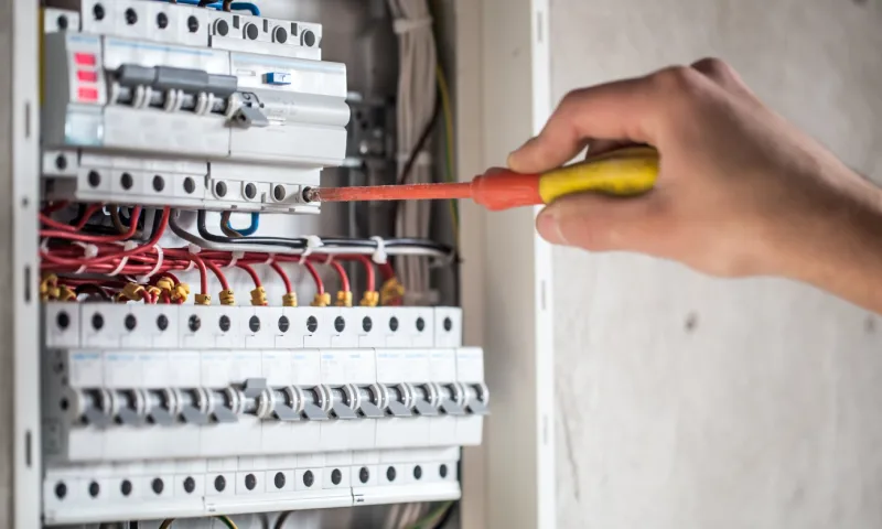
    install circuit breaker

    Circuit breakers are automatic electrical switches designed to protect electrical circuits from damage caused by overcurrent, short circuits, and ground faults. They interrupt electrical flow when dangerous conditions are detected, preventing fires, equipment damage, and electrical hazards.

    Key Functions:

    • Overcurrent protection
    • Short circuit interruption
    • Ground fault detection
    • Manual disconnection capability
    • System isolation for maintenance

    Residential Circuit Breakers: Definition and Purpose

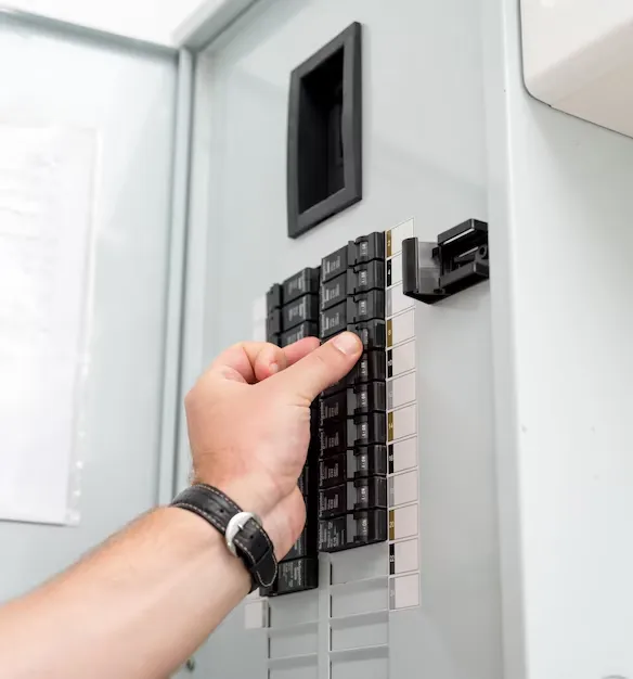
    Residential circuit breakers protect home electrical systems by monitoring current flow in individual circuits serving outlets, lights, and appliances. They’re designed for single-family homes, apartments, and small commercial buildings.

    Primary Applications:

    • Lighting circuits (15-20 amps)
    • General outlet protection (15-20 amps)
    • Kitchen and bathroom circuits (20 amps GFCI)
    • Large appliance circuits (30-50 amps)
    • Main service disconnection (100-200 amps)

    Expert Tip: Most homes use single-pole breakers for 120V circuits and double-pole breakers for 240V appliances like electric dryers and air conditioners.

    Industrial Circuit Breakers: Definition and Purpose

    Industrial Circuit Breakers

    Industrial circuit breakers protect heavy-duty electrical systems in manufacturing facilities, power plants, data centers, and large commercial buildings. They handle massive electrical loads and provide precise protection for expensive equipment.

    Primary Applications:

    • Motor control and protection
    • Power distribution systems
    • Manufacturing equipment protection
    • Emergency disconnection systems
    • Electrical grid tie-ins

    Safety Warning: Industrial circuit breakers require specialized training for installation and maintenance. Always consult qualified electrical professionals for industrial applications.

    Key Differences: Residential vs Industrial Circuit Breakers

    Feature Residential Circuit Breakers Industrial Circuit Breakers
    Amperage Range 15-200 amps 100-6,000+ amps
    Voltage Rating 120V-240V 480V-15,000V+
    Interrupting Capacity 10,000-22,000 AIC 25,000-200,000+ AIC
    Physical Size 1-4 inches wide 6-48+ inches wide
    Cost Range $5-$150 $500-$50,000+
    Installation Method Plug-in or bolt-on Bolt-on with complex wiring
    Maintenance Requirements Minimal (visual inspection) Regular testing and calibration
    Coordination Requirements Basic selectivity Complex coordination studies
    Arc Flash Hazard Low (residential level) High (requires PPE)
    Applicable Codes NEC Article 210-240 NEC Article 240, 430, IEEE standards

    Residential Circuit Breaker Types and Applications

    Standard Thermal-Magnetic Breakers

    • Application: General lighting and outlet circuits
    • Amperage: 15, 20, 30, 40, 50 amps
    • Voltage: 120V (single-pole), 240V (double-pole)
    • Cost: $8-$25 each

    GFCI Circuit Breakers

    • Application: Wet locations (bathrooms, kitchens, outdoor areas)
    • Protection: Ground fault detection (4-6 milliamp trip)
    • Code Requirement: NEC mandated for specific locations
    • Cost: $45-$85 each

    AFCI Circuit Breakers

    • Application: Bedroom and living area circuits
    • Protection: Arc fault detection and interruption
    • Code Requirement: Required in most living spaces since 2008
    • Cost: $35-$65 each

    Dual Function AFCI/GFCI

    • Application: Areas requiring both arc and ground fault protection
    • Benefits: Single device provides dual protection
    • Growing Usage: Increasingly required by newer code editions
    • Cost: $65-$120 each

    Expert Tip: Always verify local code requirements, as AFCI and GFCI requirements vary by jurisdiction and may exceed national codes.

    Industrial Circuit Breaker Types and Applications

    Molded Case Circuit Breakers (MCCB)

    • Application: Distribution panels, motor control centers
    • Amperage: 100-2,500 amps
    • Features: Adjustable trip settings, high interrupting capacity
    • Cost: $200-$2,000

    Power Circuit Breakers (PCB)

    • Application: Main distribution, large motor protection
    • Amperage: 800-6,000+ amps
    • Features: Microprocessor controls, advanced protection
    • Cost: $5,000-$50,000+

    Air Circuit Breakers (ACB)

    • Application: Low voltage distribution (up to 690V)
    • Features: Draw-out construction for maintenance
    • Benefits: High fault current interruption capability
    • Typical Use: Data centers, hospitals, manufacturing

    Vacuum Circuit Breakers (VCB)

    • Application: Medium voltage systems (1kV-35kV)
    • Features: Vacuum interrupter technology
    • Benefits: Minimal maintenance, environmental safety
    • Cost: $10,000-$100,000+

    Selection Criteria: How to Choose the Right Circuit Breaker

    For Residential Applications

    1. Load Calculation

    • Calculate total circuit load in amps
    • Apply 80% rule (continuous loads)
    • Consider future expansion needs
    • Factor in appliance starting currents

    2. Code Compliance

    • Verify AFCI requirements for living areas
    • Confirm GFCI needs for wet locations
    • Check local amendment requirements
    • Ensure proper voltage ratings

    3. Panel Compatibility

    • Match breaker brand to panel manufacturer
    • Verify physical fit and electrical ratings
    • Check available spaces and configuration
    • Consider future circuit additions

    Safety Warning: Never install a higher amperage breaker without verifying wire capacity. Using 20-amp breakers on 14 AWG wire violates NEC and creates fire hazards.

    For Industrial Applications

    1. System Analysis Requirements

    • Conduct detailed load flow studies
    • Perform short circuit analysis
    • Calculate arc flash hazard levels
    • Develop coordination study

    2. Protection Coordination

    • Ensure selective coordination between devices
    • Set time-current curves appropriately
    • Consider backup protection requirements
    • Plan for system expansion

    3. Environmental Considerations

    • Evaluate installation environment conditions
    • Consider temperature, humidity, and contamination
    • Assess seismic and vibration requirements
    • Plan for maintenance accessibility

    4. Standards Compliance

    • Follow IEEE, UL, and ANSI standards
    • Meet utility interconnection requirements
    • Ensure code compliance (NEC, local codes)
    • Consider international standards if applicable

    Installation and Maintenance Differences

    Residential Circuit Breaker Installation

    Installation Process:

    1. Turn off main power at service panel
    2. Test for absence of voltage
    3. Remove panel cover safely
    4. Install breaker in designated slot
    5. Connect circuit wiring to breaker
    6. Test operation before energizing

    Maintenance Requirements:

    • Annual visual inspection for damage
    • Test GFCI/AFCI breakers monthly
    • Check for loose connections annually
    • Replace if trips frequently or shows damage

    Expert Tip: Hire qualified electricians for panel work. DIY installation may violate local codes and insurance requirements.

    Industrial Circuit Breaker Installation

    Installation Process:

    1. Complete system shutdown and lockout
    2. Perform detailed safety analysis
    3. Use specialized lifting equipment for large units
    4. Install with precision torque specifications
    5. Conduct comprehensive testing protocols
    6. Commission with full coordination verification

    Maintenance Requirements:

    • Regular infrared scanning for hot spots
    • Annual contact resistance testing
    • Periodic mechanism lubrication
    • Coordination study updates after changes
    • Arc flash analysis updates

    Safety Considerations and Code Requirements

    Residential Safety Requirements

    NEC Compliance Points:

    • GFCI protection for wet locations (NEC 210.8)
    • AFCI protection for dwelling unit circuits (NEC 210.12)
    • Proper overcurrent protection sizing (NEC 240.4)
    • Equipment grounding requirements (NEC 250)

    Common Safety Issues:

    • Overloaded circuits leading to frequent tripping
    • Incorrect breaker sizing for wire gauge
    • Missing GFCI protection in required areas
    • Outdated panels lacking modern safety features

    Industrial Safety Requirements

    Critical Safety Elements:

    • Arc flash hazard analysis and labeling
    • Personal protective equipment requirements
    • Electrical safety training for personnel
    • Proper maintenance scheduling and documentation

    Standards Compliance:

    • IEEE 1584 for arc flash calculations
    • NFPA 70E for electrical safety training
    • OSHA 1910.333 for safe work practices
    • UL 489 for circuit breaker standards

    Safety Warning: Arc flash incidents in industrial settings can cause severe burns or death. Never work on energized industrial equipment without proper training and PPE.

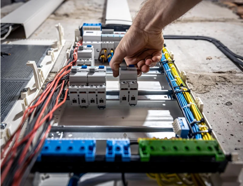
    install mcb on electrical panel

    Cost Comparison and Economic Factors

    Residential Circuit Breaker Economics

    Breaker Type Unit Cost Installation Cost Total Investment
    Standard 20A $10-20 $150-250 $160-270
    GFCI 20A $50-85 $150-250 $200-335
    AFCI 20A $40-65 $150-250 $190-315
    Main 200A $100-200 $500-1,000 $600-1,200

    Economic Considerations:

    • Higher upfront cost for AFCI/GFCI provides safety value
    • Energy-efficient breakers reduce long-term costs
    • Professional installation ensures code compliance
    • Quality breakers last 25-40 years with minimal maintenance

    Industrial Circuit Breaker Economics

    Breaker Type Equipment Cost Installation Cost Total Investment
    400A MCCB $800-1,500 $2,000-4,000 $2,800-5,500
    1200A PCB $8,000-15,000 $10,000-20,000 $18,000-35,000
    3000A ACB $25,000-40,000 $15,000-30,000 $40,000-70,000
    Medium Voltage $50,000-200,000 $25,000-75,000 $75,000-275,000

    Economic Factors:

    • Downtime costs far exceed equipment costs
    • Proper coordination prevents cascading failures
    • Predictive maintenance reduces unexpected failures
    • Energy losses from older breakers impact operating costs

    Expert Recommendations and Best Practices

    For Homeowners

    Selection Best Practices:

    • Always match breaker brand to panel manufacturer
    • Upgrade to AFCI/GFCI where required by current codes
    • Plan for future electrical needs during renovations
    • Consider whole-house surge protection integration

    Maintenance Recommendations:

    • Test GFCI/AFCI devices monthly using test buttons
    • Schedule professional panel inspection every 5 years
    • Replace breakers showing signs of arcing or frequent tripping
    • Upgrade older panels lacking modern safety features

    For Industrial Facilities

    Engineering Best Practices:

    • Conduct comprehensive system studies before equipment selection
    • Implement predictive maintenance programs using infrared scanning
    • Maintain detailed coordination studies and update with system changes
    • Train maintenance staff on proper testing procedures

    Operational Recommendations:

    • Establish clear lockout/tagout procedures for breaker maintenance
    • Document all maintenance activities for regulatory compliance
    • Implement arc flash hazard analysis and safety protocols
    • Plan equipment replacement before end-of-life conditions

    When to Call a Professional

    Residential Situations Requiring Professional Help

    • Any work involving the main service panel
    • Installation of new circuits or major appliances
    • Frequent breaker tripping without obvious cause
    • Upgrading electrical service capacity
    • Adding whole-house surge protection

    Industrial Situations Requiring Specialized Expertise

    • System coordination studies and analysis
    • Medium voltage circuit breaker installation
    • Arc flash hazard analysis and mitigation
    • Power quality investigations
    • Utility interconnection projects

    Expert Tip: For industrial applications, always engage licensed engineers and certified technicians. The complexity and safety risks require specialized expertise.

    Frequently Asked Questions

    Q: Can I replace a residential circuit breaker myself?

    A: Basic breaker replacement may be DIY in some areas, but check local codes first. Any panel work requires turning off main power and understanding electrical safety. When in doubt, hire a qualified electrician to ensure safety and code compliance.

    Q: What’s the difference between AIC and AIC ratings?

    A: AIC (Ampere Interrupting Capacity) measures a breaker’s ability to safely interrupt short circuit currents. Residential breakers typically have 10,000-22,000 AIC ratings, while industrial breakers may exceed 200,000 AIC for high fault current applications.

    Q: How often should industrial circuit breakers be tested?

    A: Testing frequency depends on criticality and manufacturer recommendations. Critical applications may require annual testing, while less critical circuits might be tested every 3-5 years. Always follow maintenance schedules based on system importance and environmental conditions.

    Q: Why are industrial circuit breakers so much more expensive?

    A: Industrial breakers handle much higher voltages and currents, require precision manufacturing, include advanced protection features, and must meet stringent safety standards. The cost reflects the engineering complexity and safety requirements for protecting expensive equipment and personnel.

    Q: Can I use an industrial circuit breaker in a residential application?

    A: While technically possible, it’s impractical due to size, cost, and complexity. Residential applications don’t require industrial-grade features, and using oversized equipment may complicate installations and create unnecessary expense.

    Q: What happens if I install the wrong type of circuit breaker?

    A: Wrong breaker selection can lead to inadequate protection, code violations, safety hazards, and insurance issues. Always verify load requirements, code compliance, and panel compatibility before installation.

    Q: How do I know when a circuit breaker needs replacement?

    A: Replace breakers that trip frequently, show burn marks, feel hot during operation, or fail to reset properly. For industrial applications, replace based on maintenance testing results and manufacturer recommendations rather than waiting for failure.

    Q: What’s the lifespan of residential vs industrial circuit breakers?

    A: Quality residential breakers typically last 25-40 years with minimal maintenance. Industrial breakers may last 20-30 years but require regular testing and maintenance to ensure reliable operation throughout their service life.

    Conclusion

    Understanding the differences between residential and industrial circuit breakers is essential for proper electrical system protection. Residential breakers focus on household safety with features like AFCI and GFCI protection, while industrial breakers provide sophisticated protection for complex electrical systems with high fault currents and coordination requirements.

    For residential applications, prioritize code compliance with AFCI and GFCI protection where required, and always match breaker specifications to circuit requirements. For industrial applications, invest in comprehensive system analysis, proper coordination studies, and regular maintenance programs to ensure reliable operation and personnel safety.

  • DC vs AC Isolator Switch: What Is the Difference?

    DC vs AC Isolator Switch: What Is the Difference?

    AC and DC isolator switches serve the same basic purpose: they create an isolation point so equipment can be separated from its source. Their electrical ratings, however, are not interchangeable.

    Use a device on a DC circuit only when the manufacturer explicitly declares a suitable DC operational voltage, current, utilization category, and required pole or wiring arrangement. An AC voltage printed on the label cannot be converted into a safe DC rating with a universal ratio. The reverse is also true: a DC rating does not automatically establish suitability for an AC application.

    The practical decision rule is simple:

    Match the device to the current type, system voltage, load duty, pole arrangement, and manufacturer instructions. If the required AC or DC rating is absent, treat the device as unsuitable for that application.

    DC vs AC Isolator Switch at a Glance

    Decision factor AC isolator or switch-disconnector DC isolator or switch-disconnector
    Intended circuit Alternating-current circuits Direct-current circuits
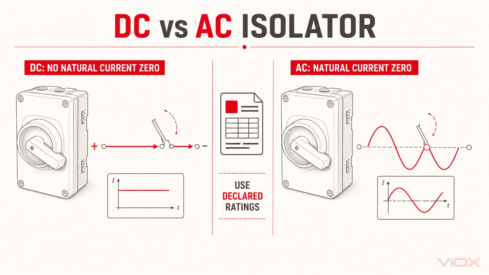
    Arc behavior when contacts open Alternating current passes through natural current zeroes, which assist arc extinction Direct current has no natural current zero-crossing, so interruption is generally more demanding
    Acceptable rating evidence Explicit AC operational voltage, current, frequency, and utilization category Explicit DC operational voltage, current, utilization category, and any required polarity or pole configuration
    Typical utilization categories under IEC 60947-3 AC-20, AC-21, AC-22, or AC-23, with A/B operation suffix where declared DC-20, DC-21, DC-22, or DC-23; some PV products also declare application-specific DC-PV categories
    Pole arrangement Selected for the AC system, phases, neutral treatment, and local rules May require contacts or poles in series and a specific positive/negative connection arrangement defined by the manufacturer
    Common applications AC distribution, HVAC equipment, motors, and industrial machinery Solar photovoltaic arrays, battery energy storage, DC distribution, and other DC systems
    Can it be used on the other current type? Only if the same product has a separate, adequate DC declaration Only if the same product has a separate, adequate AC declaration

    This comparison is about electrical suitability, not the color or external appearance of the enclosure. Two rotary isolators can look almost identical while carrying very different operational ratings.

    If you first need the device’s basic function and its place in a photovoltaic system, read what a DC isolator switch does. This page focuses specifically on the AC-versus-DC decision.

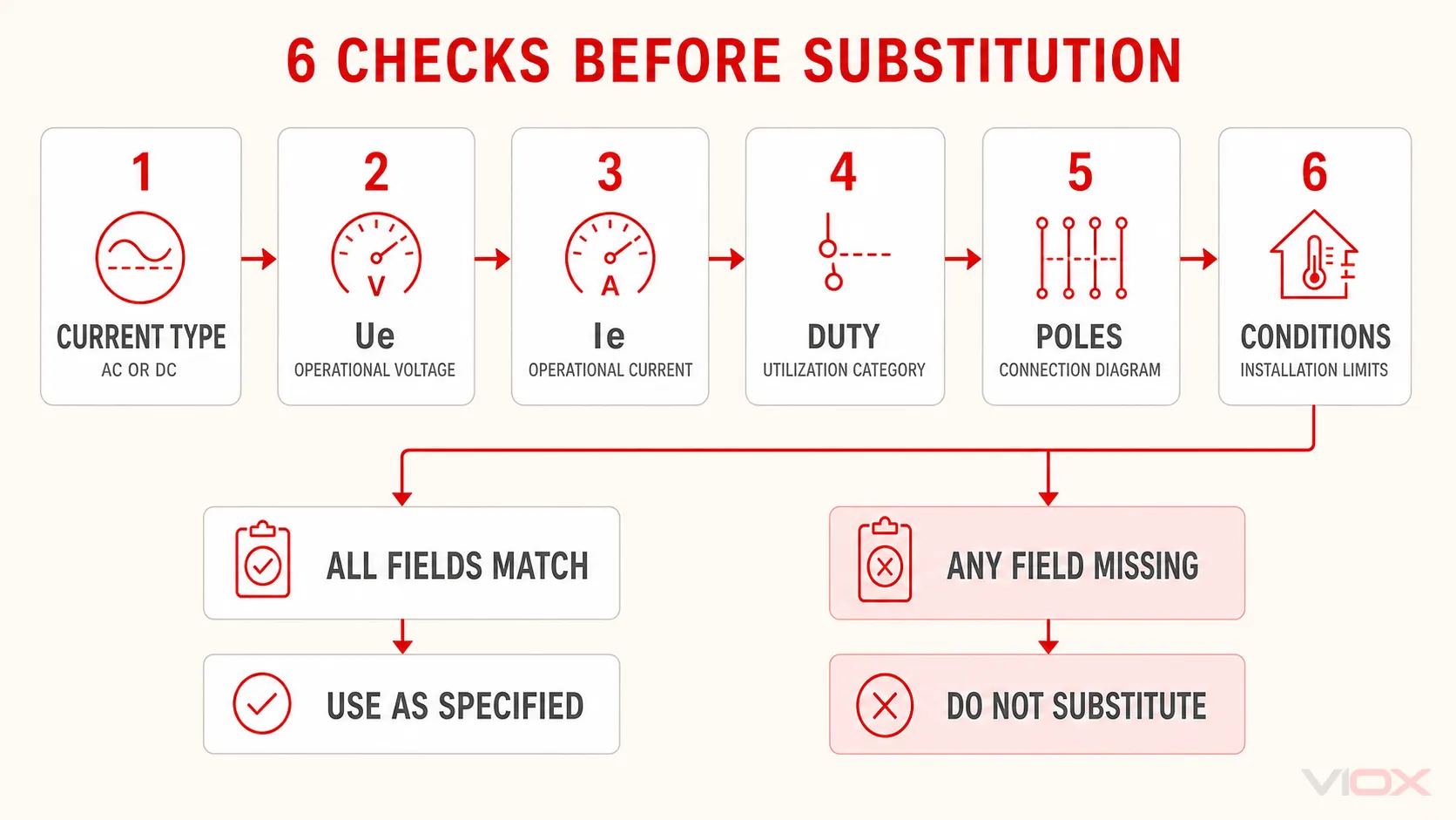
    The Six-Check Interchangeability Test

    Before substituting one isolator for another, check all six items below. A pass on only voltage or current is not enough.

    Check What to find on the label or datasheet Reject the substitution when…
    1. Current type and operational voltage A declared rated operational voltage, Ue, for AC or DC at the actual system voltage The device shows only an AC value for a DC circuit, only a DC value for an AC circuit, or an inadequate voltage
    2. Operational current Rated operational current, Ie, at that voltage and duty The current value belongs to another voltage, category, temperature, or wiring configuration
    3. Utilization category AC-20/21/22/23 or DC-20/21/22/23, including the A or B suffix where applicable The category does not permit the intended load-making or load-breaking duty
    4. Device function Whether it is a disconnector, switch, or switch-disconnector A no-load disconnector is being treated as a device for normal load switching
    5. Poles and connection diagram Required number of poles, series-contact arrangement, polarity, terminal assignment, and permitted circuit configuration The proposed wiring differs from the manufacturer’s tested arrangement
    6. Installation conditions Temperature derating, enclosure/IP declaration, pollution or altitude limits, short-circuit coordination, and applicable product approval Any environmental, coordination, or market requirement is unsupported

    Quick accept-or-reject matrix

    Product declaration Proposed use Decision
    AC rating only AC circuit within all declared limits Potentially suitable; verify duty and installation conditions
    AC rating only DC circuit Reject—there is no declared DC capability
    DC rating only DC circuit within all declared limits Potentially suitable; verify duty, poles, polarity, and installation conditions
    DC rating only AC circuit Reject unless a separate AC rating is also declared
    Separate AC and DC ratings Either circuit Use only within the rating and configuration declared for that current type
    Voltage/current shown without clear current type or duty AC or DC circuit Do not assume suitability; obtain the manufacturer’s technical documentation

    A dual-rated product can therefore be used in either type of circuit, but it is not used under one universal rating. The permitted AC and DC values may differ, and the DC configuration may use a different number of poles or connection scheme.

    Six checks for AC and DC isolator switch interchangeability

    Why Switching DC Is Generally More Demanding

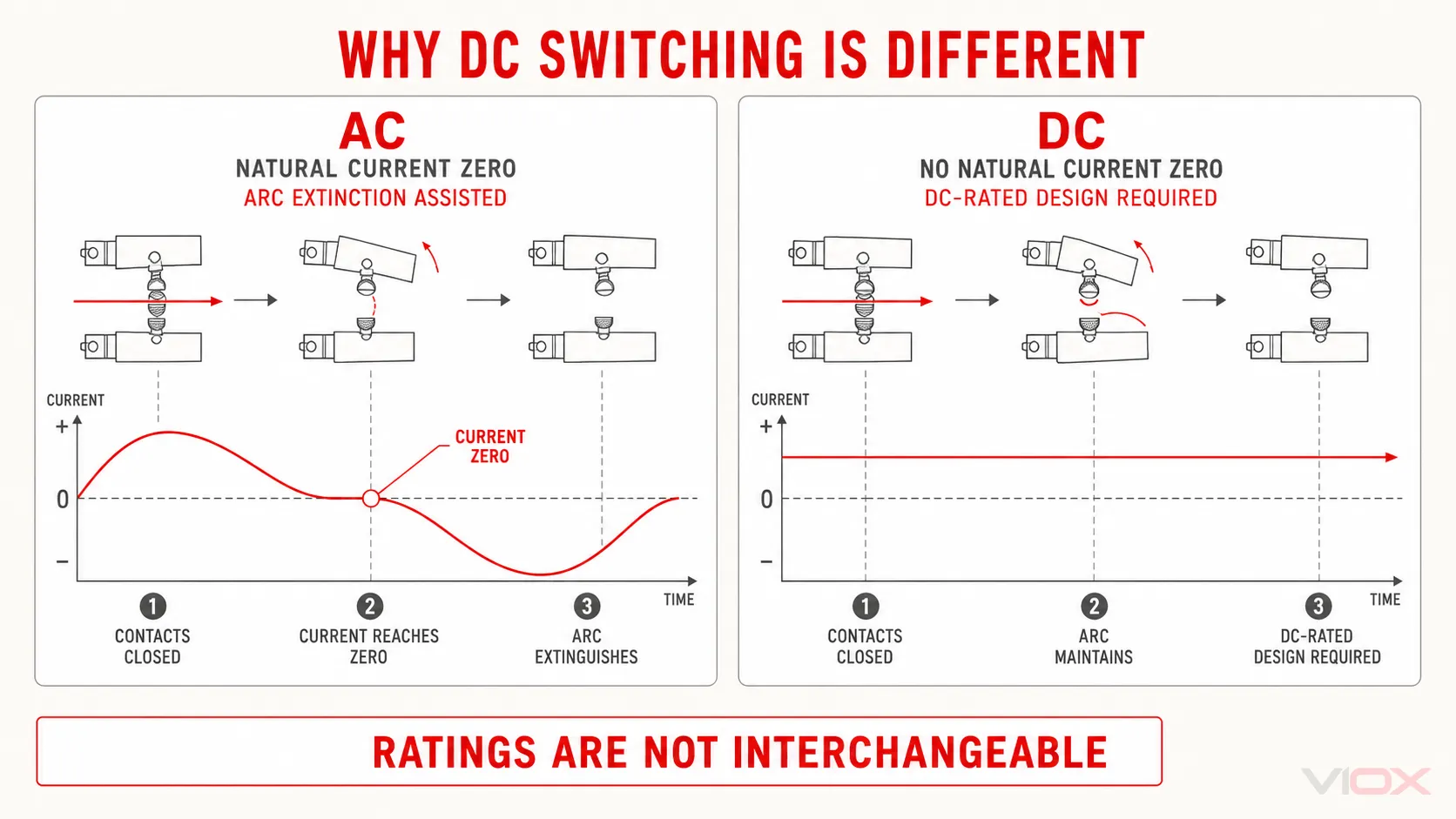
    When mechanical contacts separate while current is flowing, an electrical arc can form across the opening gap. In an AC circuit, current reverses direction and passes through zero every half-cycle. That natural current zero assists interruption because the energy sustaining the arc periodically falls to zero.

    DC current does not provide the same natural interruption point. As Schneider Electric explains in its low-voltage DC guidance, the absence of current and voltage zero-crossing makes the DC arcing time longer and increases the energy that the switching device must manage. Omron consequently advises selecting a switch with a declared DC rating when interrupting a DC circuit.

    Manufacturers address DC interruption in different ways. Product design may involve contact geometry, opening speed, arc-control components, series-connected contacts, polarity-dependent arrangements, or combinations of these measures. It is not technically sound to assume that every DC isolator must contain one particular internal component.

    The external handle also does not reveal the tested duty. The manufacturer’s AC or DC operational rating and connection diagram are the evidence that matters.

    AC current zero crossing compared with DC arc interruption in an isolator switch

    Is It a Disconnector or a Switch-Disconnector?

    The word “isolator” is often used loosely. Under the IEC 60947-3 product framework, disconnectors, switches, and switch-disconnectors are related but not identical device functions. IEC 60947-3:2020, supplemented by Amendment 1:2025, covers these product families for circuits up to 1,000 V AC or 1,500 V DC within its scope.

    The distinction changes what the device may do:

    • A disconnector provides the isolation function. A device declared only for an AC-20 or DC-20 duty is associated with connecting and disconnecting under no-load conditions.
    • A switch is intended to make, carry, and break current under declared operating conditions.
    • A switch-disconnector combines load-switching capability with the isolation function, within its declared utilization category and ratings.

    The utilization category is therefore as important as the word “isolator” on a sales page.

    IEC 60947-3 category family General duty represented by the category What it means for the decision
    AC-20 / DC-20 Connecting and disconnecting under no-load conditions Do not infer normal load-breaking capability
    AC-21 / DC-21 Switching resistive loads, including moderate overloads Verify the actual load and declared operational rating
    AC-22 / DC-22 Switching mixed resistive and inductive loads, including moderate overloads Relevant where load inductance changes the switching duty
    AC-23 / DC-23 Switching motor loads or other highly inductive loads Requires a device specifically declared for that demanding duty

    In the category suffix, A indicates frequent operation and B indicates infrequent operation. The complete category—not just the rated current—must match the application. An ABB utilization-category reference provides the AC and DC category mapping.

    This is why the blanket statement “an isolator must never be opened under load” is incomplete. It may be correct for a no-load disconnector, but a switch-disconnector can have declared making and breaking capability for normal load conditions. Neither device should be confused with automatic overcurrent protection. For that separate boundary, see DC isolator versus DC circuit breaker.

    Why There Is No Universal AC-to-DC Derating Ratio

    A frequently repeated shortcut says that an AC-rated switch can be used on DC after applying a fixed voltage reduction. That is not a dependable selection method.

    The DC capability of a device depends on more than the AC voltage printed on its label. Relevant variables can include:

    • contact and arc-control design;
    • number of poles used in series;
    • circuit time constant or inductive duty;
    • operational current and voltage together;
    • utilization category;
    • polarity and current direction;
    • opening mechanism and speed;
    • temperature and installation conditions;
    • the exact tested connection diagram.

    Manufacturer data demonstrates why the product-specific approach matters. ABB DC switch-disconnector documentation lists DC operational ratings by voltage, utilization category, pole arrangement, and circuit configuration. Socomec likewise publishes DC switch-disconnector ratings against a defined DC category and product configuration. These are declared combinations—not values calculated from one universal AC-to-DC formula.

    Accordingly:

    1. Do not convert a 690 V AC marking into an assumed DC voltage.
    2. Do not add poles in series unless the manufacturer’s diagram permits that arrangement.
    3. Do not treat the thermal current, Ith, as proof of load-switching capability at the required DC voltage.
    4. Do not use insulation voltage, Ui, in place of rated operational voltage, Ue.
    5. Obtain the exact datasheet or certificate for the model and configuration being supplied.

    What Changes Between AC and DC Applications?

    Solar photovoltaic systems

    The conductors between a photovoltaic array and inverter operate on DC, so the isolation device needs an explicit DC declaration suitable for the maximum circuit voltage, operating current, switching duty, and intended PV configuration. String open-circuit voltage can rise in cold conditions, so nominal system voltage alone is not a complete selection input.

    Some PV switch-disconnectors declare DC-PV utilization categories as well as specific pole and wiring arrangements. Use only the manufacturer’s tested configuration. For the full input-to-rating process, see how to choose a DC isolator switch.

    Battery energy storage and other DC systems

    Battery systems also require explicitly DC-rated equipment. The applicable voltage, prospective current, load inductance, grounding arrangement, poles to be disconnected, and coordination with protective devices all affect selection. A familiar AC rotary isolator is not an acceptable substitute merely because its current rating appears high enough.

    AC distribution, HVAC, and motors

    AC distribution circuits require an AC operational rating and a utilization category suited to the load. A largely resistive load and a motor load do not impose the same switching duty. For three-phase applications, the phase and neutral arrangement also has to match the circuit and local rules. The three-phase isolator switch guide covers that AC system context in more depth.

    Equipment carrying both AC and DC declarations

    Some switch-disconnectors are legitimately rated for both AC and DC. That does not make the ratings interchangeable. Read the AC row for an AC application and the DC row for a DC application, then follow the pole and connection diagram associated with that row.

    The same enclosure may therefore be suitable for 415 V AC in one configuration and a specified DC voltage in another, while having different operational currents or pole requirements. Only the product documentation can establish those limits.

    How to Read the Datasheet Before Substitution

    Use this sequence when reviewing a proposed AC/DC isolator substitution:

    1. Identify the device function. Confirm whether it is a disconnector or a switch-disconnector.
    2. Find the correct Ue row. Select the row for AC or DC and the actual circuit voltage.
    3. Read Ie on the same row. Do not borrow current from another voltage or category.
    4. Match the utilization category. Verify the load type and expected operating frequency.
    5. Check poles and the connection diagram. Follow the exact series, polarity, and terminal arrangement declared by the manufacturer.
    6. Check installation limits. Confirm temperature derating, enclosure suitability, mounting restrictions, short-circuit coordination, and required approvals.

    If any item is missing, request a model-specific datasheet, declaration, or certificate. A product photograph, marketplace title, or generic catalogue description is not sufficient engineering evidence.

    Connection details deserve their own controlled procedure. Do not infer line/load terminals, series links, or polarity from another brand’s diagram; use the supplied model instructions and the DC isolator connection requirements as background guidance.

    Frequently Asked Questions

    Can an AC isolator switch be used for DC?

    Only when the manufacturer explicitly provides a suitable DC operational voltage, current, utilization category, and connection arrangement for that exact product. If the device has only an AC rating, do not use it on DC.

    Can a DC isolator be used on AC?

    Only when the product also carries a suitable AC declaration. A DC rating alone does not establish AC utilization category, frequency, operational current, or application suitability.

    What is the main difference between an AC and DC isolator switch?

    The practical difference is the declared switching and isolation capability for the current type. AC has natural current zero-crossings that assist arc extinction; DC does not. Manufacturers therefore test and rate devices separately for AC and DC duties and may require different pole arrangements.

    Does an isolator switch break current under load?

    It depends on the device function and utilization category. A no-load disconnector is not the same as a switch-disconnector declared for normal load switching. Neither should be assumed capable of interrupting fault current like a circuit breaker.

    Is the current rating alone enough to compare AC and DC isolators?

    No. Current must be read together with current type, operational voltage, utilization category, pole arrangement, connection diagram, temperature conditions, and the intended switching duty.

    Final Decision Rule

    Choose an AC-rated isolator or switch-disconnector for an AC circuit when its voltage, current, utilization category, poles, and installation declarations match the application.

    Choose a DC-rated isolator or switch-disconnector for a DC circuit using the same evidence, including any required polarity and series-contact configuration.

    Choose a dual-rated product only by applying its AC declarations to the AC application and its DC declarations to the DC application.

    Reject the substitution when the required current-type rating, duty category, or connection arrangement is absent. There is no safe universal conversion from an AC label to a DC rating.

    After defining the required ratings, review the VIOX DC isolator switch range and request the model-specific datasheet and certification documents needed for the intended market and circuit.

    Sources Reviewed

  • Connection of DC Isolators: Complete Guide to Safe Installation and Wiring

    Connection of DC Isolators: Complete Guide to Safe Installation and Wiring

    Bottom Line Up Front: DC isolator connection requires proper terminal identification, correct polarity wiring, and compliance with AS/NZS 5033 safety standards. DC cables use Class 5 flexible conductors that must be terminated correctly to prevent failures, and consideration should be given to the termination of the DC conductor in the isolator’s terminals (526.9.1).

    What Are DC Isolators and Why Do Connections Matter?

    viox DC Isolator Switches

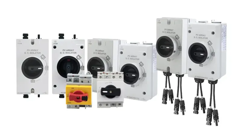
    VIOX DC Isolator

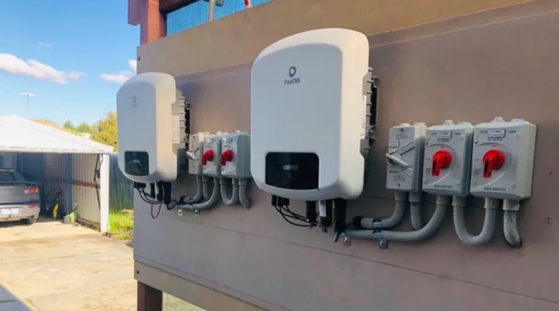
    A DC isolator (also called a DC switch-disconnector) is a safety device that provides complete electrical isolation in direct current systems, particularly in solar photovoltaic installations. By completely isolating the power source when maintenance or repairs are necessary, it ensures that no one will be electrocuted if they come in contact with an energized part of the system.

    ⚠️ Safety Warning: DC isolators have been the source of many fires and are the main cause of failure of solar PV installations. Proper connection and installation are critical for system safety and performance.

    Key Differences: DC vs AC Isolator Connections

    DC isolators face unique challenges compared to AC isolators. With an AC system operating at 50 Hz, the voltage crosses zero twice per cycle, occurring every 10 milliseconds, which helps suppress electrical arcs. However, DC voltage is constant and lacks this zero-point crossing, making arc extinction more difficult.

    DC Isolator Connection Requirements and Standards

    Primary Standards and Compliance

    • AS/NZS 5033:2021: Installation and safety requirements for photovoltaic arrays
    • AS 60947.3:2018: Modified version of IEC 60947-3 with Australia-specific requirements
    • IEC 60947-3: International standard for low-voltage switchgear and controlgear

    Switch-disconnectors must now be compliant to AS 60947.3:2018, a modified version of international standard IEC 60947.3 with requirements specific to Australia.

    Essential Connection Specifications

    Specification Requirement Standard Reference
    Conductor Class Class 5 (flexible) AS/NZS 5033
    Terminal Marking Must suit all conductor classes 526.2 Note 2
    IP Rating Minimum IP56NW outdoor AS 60947.3
    Temperature Rating 40°C (shaded) / 60°C (exposed) AS/NZS 5033:2021
    Utilization Category DC-PV2 for PV systems AS 60947.3

    Step-by-Step DC Isolator Connection Process

    Step 1: Pre-Connection Safety and Planning

    ? Expert Tip: Always ensure the power source is completely isolated before beginning any connection work. Use a multimeter to verify zero voltage at all terminals.

    1. Turn off all upstream power sources
    2. Lock out/tag out (LOTO) procedures
    3. Verify isolation with appropriate test equipment
    4. Identify positive and negative conductors using proper cable marking

    Step 2: Terminal Identification and Preparation

    DC cables generally use class 5 (flexible) conductors. Where equipment terminals are unmarked, they should be suitable for all conductor classes without modification.

    Terminal Preparation Requirements:

    • Strip cable insulation to manufacturer specifications
    • Where treatment of the conductors at the terminations is necessary reference should be made to manufacturer’s data, which may state that a fine wire conductor requires a sleeve or ferrule
    • Ensure clean, corrosion-free terminal surfaces
    • Apply anti-oxidant compound if specified

    Step 3: Understanding Connection Configurations

    Different DC isolator types require specific wiring configurations based on voltage and current requirements:

    Standard Configuration Options

    Configuration Voltage Rating Current Capacity Applications
    2-pole Series Up to 600V Lower current Single string systems
    4-pole Series Up to 1000V Medium current High voltage arrays
    2-pole Series + 2-pole Parallel Variable Higher current Multiple string systems

    Using the voltage and current values determined previously, the appropriate wiring configuration can be selected from Table 1. For switching 15.6 A at 936 V, the disconnector should be wired either in a 4-pole series configuration or a 2-pole series + 2-pole parallel configuration.

    Step 4: Physical Connection Process

    For Standard 2-Pole DC Isolators:

    1. Identify input and output terminals (often marked L1/L2 for input, T1/T2 for output)
    2. Connect positive conductor to designated positive terminal
    3. Connect negative conductor to designated negative terminal
    4. Tighten connections to manufacturer’s torque specifications
    5. Verify polarity before energizing

    ⚠️ Critical Warning: Connections are diagonal, so wiring straight through will result in reversed polarity. Always verify connection paths using continuity testing.

    Step 5: Connection Verification and Testing

    Essential Verification Steps:

    1. Visual inspection of all connections
    2. Continuity testing with isolator in ON position
    3. Insulation resistance testing with isolator in OFF position
    4. Polarity verification using appropriate test equipment
    5. Operational testing of switching mechanism

    Flame-retardant shell DC isolator switch

    Current and Voltage Sizing for DC Isolator Connections

    Calculating Maximum Current Requirements

    When selecting equipment for PV arrays, including DC isolators, the short-circuit maximum current (ISC MAX) shall be used (712.512.1.2). Formula 2 can be used to calculate this value: ISC MAX = No. of strings x ISC STC x 1.25

    Where:
    ISC MAX = Array maximum short-circuit current
    No. of strings = Total number of strings in parallel
    ISC STC = Short-circuit current under standard test conditions
    1.25 = Safety multiplier for higher irradiance conditions

    Temperature Considerations

    For isolators that are located indoors or outdoors in a fully shaded location, the specified ambient temperature applicable is 40 degrees Celsius. For isolators that are located outdoors and exposed to sunlight, the applicable ambient temperature is 60 degrees Celsius.

    DC Isolator Types and Connection Methods

    Switch-Disconnector Types

    Type Connection Method Applications Key Features
    Rotary Isolators Diagonal terminal configuration Solar PV systems Knife-edge contacts, IP67 rating
    Load Break Switches Standard terminal blocks Industrial DC systems High breaking capacity
    Integrated Isolators Internal inverter mounting Residential solar Space-saving design

    True DC vs De-rated AC Isolators

    ? Expert Tip: The IMO SI is a True DC switch – not an AC version de-rated or re-wired for DC operation. Always specify True DC isolators for reliable performance and safety.

    True DC Isolators Features:

    • Specialized arc-extinction chambers
    • DC-rated contact materials
    • Higher voltage withstand capability
    • Temperature-resistant designs

    DC Isolator Applications

    Installation Location and Mounting Requirements

    Mounting Surface Requirements

    Energy Safe recommends installing the d.c. isolator on a non-combustible surface. Where the surface is combustible AS/NZS 5033:2021 Cl. 4.5.4.1 requires a non-combustible barrier between the d.c. isolator and combustible surface.

    Non-combustible barrier specifications:

    • Must extend 200mm past isolator sides
    • Fire retardant sealant for penetrations >5mm diameter
    • Materials meeting AS 1530.1 standards

    IP Rating and Weather Protection

    To reduce water ingress and premature failure of the d.c. isolator, minimum installation safety requirements must be met in accordance with AS/NZS 5033:2021 Cl. 4.4.7 including: Strain relief provided for conductors (where conduit is not used to enter the enclosure) Maintaining IP66 Ratings of the d.c. isolator, only manufacturers entry points to be used.

    Common Connection Problems and Troubleshooting

    Frequent Connection Issues

    Problem Cause Solution
    Reversed Polarity Incorrect terminal identification Use continuity testing to verify connection paths
    Overheating Terminals Loose connections Tighten to specified torque values
    Arc Damage Incorrect switching under load Follow proper switching sequence
    Water Ingress Poor cable gland sealing Use IP rated glands and multi-hole grommets

    Prevention Strategies

    ? Expert Tip: It is important that the manufacturer’s instructions for DC disconnector configuration are followed to avoid failure of the device.

    Best Practices:

    • Always use manufacturer-approved cable entry points
    • Apply proper torque specifications to all connections
    • Verify polarity before energizing circuits
    • Implement regular inspection schedules

    Safety Standards and Certification Requirements

    Australian Regulatory Requirements

    DC isolators are classified as Level 3 electrical equipment and must be certified and registered under the national Electrical Equipment Safety System (EESS).

    Key Compliance Points:

    • EESS registration for all DC isolators
    • AS 60947.3:2018 compliance
    • IP56NW rating verification
    • Thermal rating certification at 40°C

    Installation Documentation

    Documentation is an important requirement outlined in the installation standards, AS/NZS 5033 & AS/NZS 4777.1 which must be complied with when installing a PV system.

    DC Isolator Selection Criteria

    Choosing the Right Isolator

    When selecting DC isolators for your system, consider these critical factors:

    Electrical Specifications:

    • Maximum system voltage (typically 600V residential, 1000V commercial)
    • Maximum short-circuit current capacity
    • Breaking and making current ratings
    • Utilization category (DC-PV2 for PV systems)

    Environmental Factors:

    • Installation location (indoor/outdoor)
    • Temperature exposure (shaded/direct sunlight)
    • IP rating requirements
    • Mounting surface compatibility

    Cost Considerations

    The DC isolator price, when compared to that of a DC circuit breaker, is usually lower. However, the exact cost of a switch depends on the size and features that are included in it. Basic models can start at around $20 while larger and higher-end models may cost upwards of $200.

    Frequently Asked Questions About DC Isolator Connections

    What makes DC isolator connections different from AC connections?

    DC voltage is constant and lacks zero-point crossing, making arc extinction more difficult. This requires specialized contact materials and arc-extinction chambers in DC isolators that are not needed in AC applications.

    Can I use an AC isolator for DC applications?

    No. DC isolator switches are specifically designed for DC power systems. For AC systems, you need to use AC-rated isolator switches. Using the wrong type can result in dangerous failures and fire hazards.

    What cable types should be used with DC isolators?

    DC cables generally use class 5 (flexible) conductors. These provide better flexibility and reliability in PV installations compared to solid conductors.

    How do I verify correct polarity after connection?

    Use continuity testing with the isolator in the ON position and verify the connection path matches the intended circuit polarity. Connections are diagonal, so wiring straight through will result in reversed polarity.

    What IP rating is required for outdoor DC isolators?

    Minimum ingress protection (IP) rating of IP56NW is required for outdoor isolators in individual enclosures.

    Do DC isolators require special mounting considerations?

    Yes. Energy Safe recommends installing the d.c. isolator on a non-combustible surface, and proper strain relief and weather protection must be provided according to AS/NZS 5033:2021.

    Professional Installation and Maintenance Recommendations

    When to Engage Professional Electricians

    While basic DC isolator connections may seem straightforward, professional installation is recommended for:

    • Systems above 48V DC
    • Commercial and industrial installations
    • Complex multi-string configurations
    • Compliance certification requirements

    Maintenance Schedule

    Annual Inspections Should Include:

    • Visual inspection of connections for signs of overheating
    • Verification of IP rating integrity
    • Operational testing of switching mechanism
    • Torque verification of terminal connections
    • Documentation updates as required

    Key Takeaway: Proper DC isolator connection requires understanding of specialized DC switching requirements, compliance with current safety standards, and attention to critical details like terminal identification and polarity verification. Always prioritize safety and consider professional installation for complex systems or when uncertain about specific requirements.

    For Professional Installation: Contact a licensed electrical contractor familiar with AS/NZS 5033:2021 requirements and DC isolation systems to ensure safe, compliant installation that protects both personnel and equipment.

    Related

    What Is a DC Isolator Switch

    How to Choose the Right DC Isolator Switch:A Complete Guide

    Global DC Isolator Switch Trend: Why More Companies Are Choosing Chinese Suppliers

  • How to Identify Circuit Breaker Brand

    How to Identify Circuit Breaker Brand

    Direct Answer: You can identify your circuit breaker brand by checking the manufacturer’s name printed on the breaker handle or body, looking for model numbers on the side or back, and examining the electrical panel’s main label which typically lists compatible breaker brands.

    Knowing your circuit breaker brand is essential for electrical safety, code compliance, and proper replacement. Using the wrong breaker brand can create fire hazards, void warranties, and violate electrical codes.

    30A AMP Breaker

    VIOX Circuit Breaker

    What is a Circuit Breaker Brand and Why Does It Matter?

    A circuit breaker brand refers to the manufacturer that produces the protective electrical device designed to automatically stop electrical flow when circuits become overloaded. The brand determines compatibility with your electrical panel and ensures proper safety function.

    Circuit breaker brands matter because:

    • Safety compliance: Only compatible breakers meet UL (Underwriters Laboratories) safety standards
    • Code requirements: National Electrical Code (NEC) requires manufacturer-approved breakers
    • Insurance coverage: Wrong breakers may void homeowner’s insurance
    • Fire prevention: Incompatible breakers can cause arcing and electrical fires

    ⚠️ Safety Warning: Never install a circuit breaker from a different brand than what your panel manufacturer specifies. This creates serious fire and electrocution hazards.

    Major Circuit Breaker Brands: Complete Identification Guide

    Brand Common Markings Panel Compatibility Key Features
    Square D “Square D”, “QO”, “Homeline” Square D panels only Green test buttons, white trip indicators
    Siemens “Siemens”, “Murray”, “ITE” Siemens/Murray/ITE panels Blue or black handles, silver trip flags
    General Electric (GE) “GE”, “THQL”, “THQP” GE panels only Gray handles, red trip indicators
    Eaton/Cutler-Hammer “Eaton”, “C-H”, “BR”, “CH” Eaton/Cutler-Hammer panels Brown or black handles, orange trip flags
    Westinghouse “Westinghouse”, “Bryant” Westinghouse panels Black handles, white trip indicators
    Federal Pacific “FPE”, “Stab-Lok” Federal Pacific panels ⚠️ Discontinued – safety hazard

    Step-by-Step Circuit Breaker Brand Identification Process

    Step 1: Ensure Electrical Safety

    • Turn off main power at the electrical meter
    • Use a non-contact voltage tester to verify power is off
    • Have a flashlight ready for clear visibility
    • Never touch exposed wires or terminals

    Step 2: Examine the Panel Door Label

    1. Open your electrical panel door
    2. Look for a metal label on the panel door or frame
    3. Find the manufacturer name (usually in large letters)
    4. Note any model numbers or part numbers listed
    5. Check for UL listing information

    Step 3: Inspect Individual Circuit Breakers

    1. Look at the breaker handles for printed manufacturer names
    2. Check the sides of breakers for model numbers
    3. Examine the back of breakers (if safely accessible)
    4. Note any color coding or distinctive markings

    Step 4: Document Your Findings

    • Take photos of panel labels and breaker markings
    • Write down model numbers and part numbers
    • Note the amperage ratings of existing breakers
    • Record the total panel amperage capacity

    ? Expert Tip: If markings are worn or unclear, use a magnifying glass and bright LED light to read faded text more clearly.

    technician-works-with-20 Amp Circuti breaker

    Visual Identification Guide: What to Look For

    Handle Markings

    Most circuit breakers display the manufacturer name prominently on the switch handle:

    • Square D: “SQUARE D” printed in white letters
    • Siemens: “SIEMENS” in silver or white text
    • GE: “GE” logo with company name
    • Eaton: “EATON” or “C-H” markings

    Model Number Locations

    Circuit breaker model numbers appear in these common locations:

    1. Side edge of the breaker body (most common)
    2. Back face of the breaker (requires removal to see)
    3. Top edge near the handle connection
    4. Bottom edge near the connection points

    Color Coding and Visual Cues

    Brand Handle Color Trip Indicator Unique Features
    Square D Black/White White flag Green test button on GFCI
    Siemens Blue/Black Silver flag Curved handle design
    GE Gray Red flag Square handle shape
    Eaton Brown/Black Orange flag Distinctive “CH” molding

    BH-P 30A breaker

    Common Applications and Use Cases

    Residential Panel Identification

    Most common scenario: Homeowner needs to replace a tripped breaker

    • Quick check: Look at existing breakers for brand consistency
    • Panel compatibility: Match new breaker to existing panel brand
    • Amperage matching: Ensure replacement has same amp rating

    Commercial Building Assessment

    Professional application: Electrician servicing commercial property

    • Multi-panel systems: Different panels may have different brands
    • Code compliance: Verify all breakers meet current NEC standards
    • Upgrade planning: Identify obsolete breakers needing replacement

    Safety Inspection Requirements

    Home inspection context: Real estate transaction electrical assessment

    • Federal Pacific identification: Critical for safety recommendations
    • Age assessment: Older brands may need updating for insurance
    • Capacity evaluation: Ensure breakers match modern electrical loads

    How to Choose the Right Replacement Circuit Breaker

    Compatibility Requirements

    Primary rule: New breakers must be designed specifically for your panel brand.

    Verification checklist:

    • ✅ Same manufacturer as electrical panel
    • ✅ Correct amperage rating (never exceed original)
    • ✅ Proper voltage rating (120V, 240V, etc.)
    • ✅ UL listed for your specific panel model

    Where to Purchase Compatible Breakers

    1. Electrical supply stores: Best selection and expert advice
    2. Home improvement centers: Common brands readily available
    3. Online retailers: Wider selection but verify compatibility
    4. Manufacturer direct: Guaranteed compatibility for specific models

    ? Expert Tip: Always bring your old breaker or clear photos to the store to ensure exact compatibility.

    Troubleshooting Common Identification Problems

    Faded or Missing Labels

    Problem: Age and wear make markings unreadable
    Solution:

    • Check the electrical panel main label for manufacturer information
    • Look for any remaining clear markings on other breakers
    • Consult original home electrical permits (available from building department)
    • Have a licensed electrician identify the panel type

    Mixed Breaker Brands

    Problem: Different breaker brands in the same panel
    Solution:

    • Immediate safety concern: Have electrician inspect for code violations
    • Replacement strategy: Use only panel manufacturer’s breakers going forward
    • Insurance implications: Document non-compliant installations for coverage

    Obsolete or Discontinued Brands

    Problem: Old breakers no longer manufactured
    Common examples: Federal Pacific, Zinsco, Challenger
    Solution:

    • Safety priority: Consider full panel replacement
    • Temporary fixes: Some retrofit breakers available (electrician-only)
    • Insurance requirements: Many insurers require panel upgrades

    Safety Warnings and Professional Recommendations

    ⚠️ Critical Safety Alerts:

    Never Mix Breaker Brands

    • Fire hazard: Incompatible breakers may not trip properly
    • Code violation: NEC Article 110.3(B) requires manufacturer approval
    • Warranty void: Mixing brands voids all manufacturer warranties

    Federal Pacific Electric (FPE) Panels

    • Stop using immediately: FPE Stab-Lok breakers have documented failure rates
    • Fire risk: May not trip during overload conditions
    • Replace entire panel: No safe repair options available

    When to Call a Professional

    Contact a licensed electrician if you encounter:

    • Any Federal Pacific Electric equipment
    • Breakers that feel hot or smell burnt
    • Frequent tripping without apparent cause
    • Visible corrosion or damage to breaker connections
    • Uncertainty about proper breaker identification

    Frequently Asked Questions

    Can I use a different brand breaker in my electrical panel?

    No, you must use breakers specifically designed and approved for your panel brand. Using incompatible breakers violates electrical codes and creates serious safety hazards including fire risk.

    How do I know if my circuit breaker is compatible?

    Check that the breaker manufacturer matches your electrical panel brand exactly. Look for UL listing information and verify the amperage and voltage ratings match your original breaker specifications.

    What happens if I install the wrong brand circuit breaker?

    Installing incompatible breakers can cause electrical fires, may not provide proper overcurrent protection, violates NEC codes, and voids manufacturer warranties. Insurance claims may also be denied.

    Are “universal” or “replacement” circuit breakers safe to use?

    Only use breakers specifically listed by UL for your exact panel model. Generic “universal” breakers are not recommended and may not meet safety standards for your specific electrical system.

    How often should circuit breakers be replaced?

    Circuit breakers typically last 25-40 years with normal use. Replace immediately if they trip frequently, feel hot, show signs of damage, or if your panel uses discontinued brands like Federal Pacific Electric.

    Can I identify my breaker brand without removing the panel cover?

    Sometimes yes – check for manufacturer labels on the panel door or frame. However, the most reliable identification requires safely examining the breakers themselves with the power off.

    Quick Reference Identification Chart

    Visual Clue Most Likely Brand Action Required
    Green test button Square D Safe to use
    Blue handle color Siemens Safe to use
    Red trip indicator General Electric Safe to use
    Orange trip flag Eaton/Cutler-Hammer Safe to use
    “Stab-Lok” marking Federal Pacific Replace immediately
    Faded/no markings Unknown/obsolete Professional inspection needed

    Professional Installation and Code Compliance

    NEC Requirements

    The National Electrical Code mandates:

    • Article 110.3(B): Equipment must be used according to manufacturer instructions
    • Article 240: Overcurrent protection devices must be properly rated
    • UL listing: All breakers must carry Underwriters Laboratories approval

    Local Code Variations

    Check with your local building department for:

    • Permit requirements for breaker replacement
    • Specific brand restrictions or approvals
    • Inspector notification requirements
    • Special commercial or industrial standards

    ? Expert Tip: Many jurisdictions require permits for electrical work. Always verify local requirements before beginning any electrical project.

    Conclusion and Next Steps

    Proper circuit breaker brand identification is crucial for electrical safety, code compliance, and fire prevention. Always use breakers specifically designed for your electrical panel brand, and never compromise on compatibility for cost savings.

    Immediate action items:

    1. Document your panel: Take photos and record manufacturer information
    2. Safety assessment: If you have Federal Pacific equipment, prioritize replacement
    3. Professional consultation: When in doubt, consult a licensed electrician
    4. Plan ahead: Keep replacement breaker information readily available for emergencies

    Remember: electrical work involves serious safety risks. When uncertain about breaker identification or compatibility, always consult with a qualified electrical professional who can ensure your safety and code compliance.

    Related

    MCB Manufacturer and supplier

    Top 10 MCB Manufacturers Dominating the Global Market in 2025

    30 Amp Breaker – Everything You Need to Know

  • Used vs New Circuit Breakers: Safety, Code, and Buying Decision Guide

    Used vs New Circuit Breakers: Safety, Code, and Buying Decision Guide

    If you are comparing used vs new circuit breakers, the short answer is this: for most residential, commercial, and light industrial replacements, a new listed breaker is the safest and most defensible choice. It gives you better traceability, cleaner code acceptance, manufacturer-backed compatibility, and fewer unknowns about prior fault history, damage, or storage conditions.

    That said, this topic is more nuanced than many articles suggest. A used breaker, a reconditioned breaker, and a new breaker are not the same thing. In legacy industrial systems, discontinued equipment, and certain low-voltage power breaker applications, buyers may still encounter reconditioned equipment as a practical option. The right decision depends on breaker type, code jurisdiction, fault duty, documentation, and how much risk your project can tolerate.

    Side-by-side comparison of a new circuit breaker and a used circuit breaker on an inspection bench
    A visual side-by-side comparison illustrating the physical differences between a brand-new circuit breaker and a used one, highlighting the importance of condition verification.

    Key Takeaways

    • In most panelboard and branch-circuit applications, new breakers are the default recommendation.
    • Used as-is and reconditioned are different categories. A used breaker with unknown history is not the same as professionally reconditioned equipment.
    • For North American projects, code treatment of reconditioned breakers depends heavily on the breaker family and adopted code edition.
    • For molded-case breakers, buyers should be especially cautious about claims around refurbishment or field reuse.
    • When legacy industrial gear forces a non-new option, supplier qualification, documentation, testing records, and AHJ acceptance matter more than sticker price.

    Used vs New vs Reconditioned Circuit Breakers at a Glance

    Technical infographic comparing new, used, and reconditioned circuit breakers
    Technical infographic detailing the engineering, warranty, and safety differences among new, used, and reconditioned circuit breakers.
    Factor New Breaker Used Breaker As-Is Reconditioned Breaker
    Condition history Known from factory Often incomplete or unknown Restored with documented work
    Listing and labeling confidence Strongest Often weakest Depends on process, markings, and jurisdiction
    Warranty Usually manufacturer-backed Often limited or none Usually seller-backed, not equivalent to new
    Code acceptance Simplest path Often hardest to justify Depends on breaker type, local code, and markings
    Compatibility risk Lower when exact match is used Higher Medium, depends on source and process
    Best fit Standard replacements, new projects, most panels Emergency stopgap only Legacy or obsolete systems under controlled conditions

    Used and Reconditioned Circuit Breakers Are Not the Same

    One reason this topic gets messy in search results is that many buyers use the words used, refurbished, rebuilt, and reconditioned as if they mean the same thing. They do not.

    A used breaker may simply be a breaker removed from another installation and resold with little or no verified restoration history. Its prior exposure to overloads, short circuits, humidity, contamination, poor storage, or mechanical wear may be unknown.

    A reconditioned breaker is a more formal category. In North American code and product-safety discussions, reconditioned equipment is expected to be identified as such, separated from its original listed condition, and backed by a known reconditioning process rather than casual resale. That does not automatically make it equivalent to new, but it is a different risk profile from buying an unknown used part from surplus stock.

    This distinction matters because many people searching for used circuit breakers are really asking two different questions:

    • Can I safely install a secondhand breaker from unknown history?
    • Can I buy a professionally reconditioned breaker for a legacy system when a new one is unavailable or uneconomical?

    Those are not the same purchasing decision.

    Why New Circuit Breakers Usually Win

    In most ordinary replacement work, new breakers win because they remove avoidable uncertainty.

    1. Better traceability

    With a new breaker, you know the manufacturer, model family, rating, marking, and intended application. That matters because exact fit is not only about amperage. It is also about:

    • panel compatibility
    • mounting format
    • interrupting rating
    • trip characteristics
    • pole configuration
    • manufacturer instructions

    If you are replacing a branch breaker in a low-voltage panel, the cleanest path is almost always an exact new replacement from the correct family, such as a properly matched MCB or MCCB, not a secondhand substitute that merely “looks close.”

    2. Cleaner code and inspection path

    Inspectors, consultants, and facility owners usually accept new listed devices far more easily than used or reconditioned ones. Even where reuse is not categorically forbidden, the burden of proof gets much heavier when you move away from new equipment.

    That matters in real projects because delays rarely come from theory. They come from practical questions such as:

    • Who supplied this breaker?
    • Is it the exact approved type?
    • Has it been altered?
    • Is it marked as reconditioned?
    • Does the AHJ accept it for this installation?

    3. Lower hidden-risk exposure

    Circuit breakers are mechanical and thermal devices. Even when they appear visually acceptable, hidden issues may remain:

    • weakened springs
    • contact wear
    • arc-chute damage
    • contamination
    • heat aging
    • improper storage
    • incomplete accessories

    These risks are harder to justify when a new breaker is readily available.

    4. Better warranty and accountability

    A new breaker usually comes with a clearer commercial chain:

    • manufacturer
    • authorized channel
    • datasheet
    • warranty
    • support

    Used breakers often shift the risk back to the buyer. If the seller cannot provide meaningful documentation, the price discount may not be worth the operational risk.

    When New Breakers Are the Right Choice Without Much Debate

    For these situations, the answer is usually straightforward: buy new.

    Residential and small commercial panel replacements

    For homes, apartments, offices, and small commercial panels, the priority is usually code-compliant replacement with minimal ambiguity. If you are replacing a branch device, a new breaker is the sensible default.

    Modern molded-case breaker applications

    If your system uses standard panelboard or feeder-style molded-case breakers, buyers should be cautious about any claim that a secondhand unit is “just as good as new.” In North American practice, molded-case breaker reconditioning is treated much more restrictively than many buyers assume. If your project depends on clean inspection acceptance and low liability, new is the safer path.

    To understand where molded-case devices fit in the protection hierarchy, see What Is a Molded Case Circuit Breaker (MCCB)?.

    Projects with strict owner, insurer, or consultant requirements

    Even when a reused device is technically possible, project stakeholders may reject it for commercial reasons:

    • insurance scrutiny
    • client specifications
    • maintenance policy
    • warranty expectations
    • auditability

    When those factors matter, new equipment is usually easier to defend than surplus or reconditioned stock.

    When Reconditioned Equipment May Still Be Considered

    There are real-world situations where buyers still evaluate reconditioned equipment, especially in industrial and legacy systems:

    • obsolete switchgear
    • discontinued breaker families
    • long OEM lead times
    • shutdown-sensitive facilities
    • temporary continuity needs during modernization

    This is much more common with larger and older power-distribution equipment than with ordinary panelboard branch devices.

    In those cases, the real question becomes:

    Is the equipment merely used, or is it professionally reconditioned, documented, correctly marked, and acceptable under the project’s code and authority structure?

    That is a very different question from buying a used breaker from an unknown reseller and hoping it works.

    Technical flowchart showing how to choose between new, used, and reconditioned circuit breakers
    A decision-making workflow to help you choose the right circuit breaker condition based on your application, documentation availability, and environmental factors.

    Code and Listing Reality: What Buyers Often Miss

    In North American practice, breaker family matters

    Recent NEC cycles added clearer language around reconditioned equipment. A practical takeaway for buyers is that not all breaker families are treated the same way. In particular, molded-case circuit breakers are treated much more strictly than some larger power circuit breakers.

    For example, NEC 2020 Section 240.88(A)(1) states that molded-case circuit breakers shall not be permitted to be reconditioned. The same section allows certain low- and medium-voltage power circuit breakers to be reconditioned, which is exactly why buyers should not treat every breaker family the same way. In the same code cycle, 110.21(A)(2) also tightened expectations around how reconditioned equipment must be identified and marked.

    That means you cannot apply a single rule to every breaker on the market.

    Marking and traceability matter

    Where reconditioned equipment is permitted, the conversation is not just about whether the device works. It is also about:

    • how it is identified
    • who performed the work
    • whether original listing assumptions still apply
    • what documentation exists
    • whether the AHJ accepts it

    If a seller cannot clearly explain those points, the buyer is carrying too much of the risk.

    Used “as removed” is the hardest category to defend

    A breaker taken from another panel and resold with little history is usually the weakest option from a compliance and risk standpoint. Even if it looks physically intact, the unknowns are significant.

    Safety and Reliability Risks With Used Breakers

    The main problem with used breakers is not that every secondhand device fails. The problem is that you rarely know enough about its history to trust it confidently.

    Questions that matter:

    • Has it interrupted a severe fault before?
    • Was it exposed to moisture, contamination, or heat?
    • Were accessories removed or changed?
    • Was it stored correctly?
    • Was it ever mechanically stressed during removal?
    • Is the exact catalog number correct for this panel?

    These are not cosmetic questions. They affect whether the breaker will trip correctly, remain stable under load, and coordinate with the rest of the system.

    If you need a broader refresher on breaker families and where they are used, see Types of Circuit Breakers.

    Cost: Cheap Purchase Price vs Defensible Total Cost

    Used breakers attract buyers for one reason: price. But a lower purchase price is not the same as lower total cost.

    What buyers tend to count

    • lower unit price
    • faster access to old models
    • no waiting for factory lead time

    What buyers often forget to count

    • verification time
    • mismatch risk
    • inspection delays
    • rework labor
    • warranty limitations
    • unplanned outage cost
    • reputational risk if the device fails

    A breaker is not a decorative component. It is a protection device. Once you factor in labor, project delay, troubleshooting, and liability, a new breaker is often the lower-risk business decision even when the sticker price is higher.

    How to Evaluate a Reconditioned Breaker Supplier

    If your project genuinely requires looking beyond new equipment, the most useful part of the page should be the evaluation checklist.

    Ask the supplier:

    1. Is this breaker used as-is or formally reconditioned?
    2. What breaker family is it: panelboard molded-case, feeder MCCB, low-voltage power breaker, or another type?
    3. What documentation shows the work performed?
    4. Is there traceable testing documentation?
    5. Is the device clearly marked according to the applicable reconditioned-equipment requirements?
    6. What warranty is provided, and by whom?
    7. Is the exact catalog number and accessory configuration verified?
    8. Has the breaker been exposed to flood, fire, contamination, or abnormal environmental damage?
    9. Has the AHJ, consultant, or facility standard accepted this type of replacement on the project?

    If the supplier cannot answer these questions cleanly, the price discount is probably not enough.

    Used vs New Circuit Breakers by Application

    Application Recommended Direction Why
    Residential branch circuit replacement New Lowest ambiguity, easiest code acceptance
    Small commercial panelboard replacement New Better fit, warranty, and inspection outcome
    Standard feeder MCCB replacement where new stock exists New Cleaner technical and commercial path
    Legacy industrial switchgear with obsolete parts Case-by-case Reconditioned may be evaluated if documentation is strong
    Emergency continuity in aging facilities Case-by-case Requires engineering review, supplier qualification, and authority acceptance

    New vs Used for Molded-Case vs Power Breakers

    Technical diagram showing the difference between molded-case and legacy power breaker replacement scenarios
    Technical breakdown comparing the replacement decision-making process for modern molded-case circuit breakers (MCCB) versus legacy low-voltage power breakers.

    Molded-case breakers

    This is the category most buyers are dealing with in ordinary commercial and industrial distribution. In this area, the case for buying new is strongest. If you need a refresher on how molded-case devices work, see What Is a Molded Case Circuit Breaker (MCCB)?.

    Power breakers and legacy switchgear

    Large low-voltage power breakers and older switchgear ecosystems are where reconditioned equipment discussions become more realistic. The decision is still not casual, but the industrial market does treat these cases differently from ordinary molded-case replacements.

    If your project is in that category, this page should not promise a universal yes or no. It should guide the reader toward a documented, authority-aware decision.

    Common Mistakes Buyers Make

    Assuming any breaker with the same amp rating is interchangeable

    Amp rating alone is not enough. Breakers must match the approved family, mounting method, fault rating, and application.

    Treating “used” and “reconditioned” as synonyms

    This is one of the biggest mistakes in the market. A used breaker with unknown history is not automatically equivalent to a documented reconditioned device.

    Ignoring code edition and AHJ interpretation

    Breaker reuse decisions are not just product questions. They are project-acceptance questions.

    Buying from a parts reseller without enough documentation

    In obsolete-equipment markets, documentation quality often matters more than the seller’s marketing language.

    Looking only at purchase price

    If the breaker later causes delay, rejection, or failure, the cheap purchase was not cheap.

    Frequently Asked Questions

    Are used circuit breakers safe?

    Some used breakers may still operate, but safety is not the right threshold for purchasing. The real issue is whether the device has a known history, the correct rating and compatibility, and enough documentation to justify installation. For most ordinary replacements, a new breaker is the safer and more defensible choice.

    Are used and reconditioned circuit breakers the same?

    No. A used breaker may simply be removed from another installation and resold. A reconditioned breaker is expected to have gone through a documented restoration process and, where applicable, different identification and marking treatment.

    Can molded-case circuit breakers be reconditioned?

    This depends on the governing code framework and jurisdiction, but in North American practice molded-case breaker reconditioning is treated much more restrictively than many buyers assume. Always verify the adopted code edition, the breaker family, and AHJ expectations before relying on any supplier claim.

    When is a new circuit breaker the best choice?

    In most residential, commercial, panelboard, and ordinary feeder replacements, new is the best choice because it offers clearer traceability, compatibility, warranty, and inspection acceptance.

    When might reconditioned equipment still be considered?

    Usually in legacy industrial systems, discontinued gear, or situations where the original device family is difficult to source new and the project can support a more controlled engineering review.

    What should I ask before buying anything other than new?

    Ask for the exact catalog number, breaker family, documented condition, test records, warranty terms, markings, and whether the project authority accepts that category of replacement.

    Final Recommendation

    If your application is a normal panel or feeder replacement, buy new. That is the cleanest answer technically, commercially, and from a code-risk standpoint.

    If your application involves obsolete industrial equipment, do not jump from “new is unavailable” to “used is fine.” First determine whether the breaker is:

    • new
    • used as-is
    • formally reconditioned

    Then evaluate the device family, documentation, markings, supplier credibility, and project authority requirements before making the decision.

    For adjacent topics, you can continue into:

  • The Complete Guide to Electrical Panel Labeling: Safety, Code Compliance & Best Practices

    The Complete Guide to Electrical Panel Labeling: Safety, Code Compliance & Best Practices

    Proper electrical panel labeling is a critical safety requirement that helps prevent electrical accidents, ensures code compliance, and enables quick circuit identification during emergencies. You need to label every circuit breaker clearly and accurately to meet National Electrical Code (NEC) requirements and protect your family or employees from electrical hazards.

    ? Expert Tip: A properly labeled electrical panel can save you hours of troubleshooting time and potentially prevent dangerous electrical accidents. It’s not just recommended—it’s required by electrical codes nationwide.

    What Is Electrical Panel Labeling?

    Electrical Panel Labeling

    Electrical panel labeling refers to the systematic identification of each circuit breaker or fuse in your electrical distribution panel with clear, descriptive text that indicates what electrical loads each circuit controls. You accomplish this by attaching durable labels that specify which rooms, outlets, appliances, or fixtures each breaker protects.

    Key Components of Proper Panel Labeling

    • Circuit identifier numbers (matching your home’s electrical plan)
    • Room or area descriptions (Kitchen, Master Bedroom, Garage)
    • Specific load descriptions (Dishwasher, AC Unit, Bathroom GFCI)
    • Amperage ratings (15A, 20A, 30A circuits)
    • Special circuit designations (AFCI, GFCI protection noted)

    Main Breaker

    Why Electrical Panel Labeling Matters: Critical Safety & Code Benefits

    1. Emergency Response Speed

    When electrical emergencies occur, you need to shut off power immediately. Proper labeling allows you to identify and disconnect the correct circuit within seconds, preventing fires, electrocution, or equipment damage.

    2. NEC Code Compliance (Article 408.4)

    The National Electrical Code requires that “each circuit and circuit modification shall be legibly marked to indicate its purpose or use.” Failure to comply can result in code violations during inspections.

    3. Maintenance and Troubleshooting Efficiency

    You save significant time and money when electricians can quickly identify circuits without testing each breaker individually. This reduces service call costs and minimizes electrical work disruption.

    4. Property Value and Insurance Benefits

    A properly labeled panel demonstrates electrical system maintenance and may qualify you for insurance discounts while increasing your home’s resale value.

    ⚠️ Safety Warning: Never work on electrical panels while power is on. Always shut off the main breaker and verify circuits are de-energized with a non-contact voltage tester before performing any labeling work.

    girl open the electrical panel cover

    Electrical Panel Labeling Methods: Complete Comparison

    Labeling Method Durability Cost Installation Time Professional Appearance Code Compliance
    Adhesive Vinyl Labels Excellent (10+ years) $15-30 2-3 hours Excellent ✅ Full
    Laminated Paper Labels Good (5-7 years) $8-15 1-2 hours Good ✅ Full
    Handwritten Labels Poor (1-2 years) $5-10 1 hour Poor ⚠️ Temporary Only
    Embossed Plastic Tags Excellent (15+ years) $25-50 3-4 hours Excellent ✅ Full
    Digital Label Makers Very Good (8-12 years) $40-80 2-3 hours Very Good ✅ Full

    ? Expert Tip: Choose adhesive vinyl labels or digital label makers for the best combination of durability, appearance, and cost-effectiveness. These methods provide clear, long-lasting identification that meets professional standards.

    rcbo in panel 2

    Essential Information to Include on Panel Labels

    Standard Circuit Labeling Format

    Your electrical panel labels should include these critical elements:

    1. Primary Description: Room or general area (Kitchen, Living Room)
    2. Secondary Description: Specific loads (Outlets, Lights, Appliances)
    3. Amperage Rating: Circuit capacity (15A, 20A, 30A)
    4. Special Designations: Protection types (GFCI, AFCI, Dedicated)

    Labeling Examples for Different Circuit Types

    Circuit Type Recommended Label Format Example
    General Lighting Room + “Lights” “Master Bedroom Lights – 15A”
    General Outlets Room + “Outlets” “Kitchen Outlets – 20A GFCI”
    Dedicated Appliance Specific Appliance “Dishwasher – 20A Dedicated”
    HVAC Systems System + Zone “AC Unit – 30A”
    Special Circuits Location + Type “Bathroom GFCI – 20A”

    Step-by-Step Electrical Panel Labeling Process

    Phase 1: Safety Preparation and Circuit Mapping

    1. Turn off the main breaker to ensure your safety during the labeling process
    2. Gather necessary tools: Non-contact voltage tester, flashlight, labels, pen
    3. Create a circuit map by testing each breaker with a helper turning loads on/off
    4. Document your findings on a panel schedule sheet or smartphone app
    5. Verify all circuits are properly identified before proceeding to labeling

    Phase 2: Label Creation and Installation

    1. Choose appropriate labeling materials based on your panel environment and budget
    2. Create clear, concise labels using the standard format outlined above
    3. Clean the panel surface with a damp cloth to ensure proper label adhesion
    4. Apply labels systematically starting from the top left and working down
    5. Verify label placement corresponds exactly to your circuit mapping documentation

    Phase 3: Testing and Documentation

    1. Turn the main breaker back on and test each labeled circuit
    2. Confirm accuracy by operating the loads connected to each labeled breaker
    3. Create a master electrical panel schedule for your home records
    4. Photograph the completed panel for insurance and maintenance records
    5. Update labels immediately if you make any electrical modifications

    ⚠️ Safety Warning: If you discover unlabeled or improperly wired circuits during this process, contact a licensed electrician immediately. Do not attempt to trace complex wiring yourself.

    Code Requirements and Compliance Standards

    National Electrical Code (NEC) Requirements

    The NEC Article 408.4 specifically mandates that electrical panels must have proper circuit identification. Here are the key compliance requirements you must follow:

    • Legible markings: Labels must be clearly readable and permanently attached
    • Accurate descriptions: Labels must accurately reflect the circuit’s actual use
    • Durable materials: Labels must withstand normal environmental conditions
    • Immediate updates: Changes to circuits require prompt label updates

    Local Code Variations

    Jurisdiction Type Common Additional Requirements Compliance Notes
    Commercial Buildings Detailed load calculations on labels Requires professional documentation
    Historic Properties Specific labeling formats required Check local preservation guidelines
    Multi-Family Units Unit-specific circuit identification Must include apartment/unit numbers
    Industrial Facilities Voltage and phase markings mandatory Requires electrical engineer approval

    ? Expert Tip: Always check with your local building department for specific labeling requirements in your area. Some jurisdictions require professional electrician verification of panel labeling for permits.

    Common Electrical Panel Labeling Mistakes to Avoid

    Critical Errors That Compromise Safety

    • Using vague descriptions like “Misc” or “Spare” instead of specific load identification
    • Failing to update labels after electrical modifications or renovations
    • Using temporary materials that fade, peel, or become illegible over time
    • Incorrect amperage ratings that don’t match the actual breaker specifications
    • Missing GFCI/AFCI designations required for safety and code compliance

    Professional Quality Standards

    • Consistent formatting: Use the same label style and format throughout the panel
    • Proper spacing: Ensure labels don’t interfere with breaker operation
    • Weather resistance: Choose materials appropriate for panel environment conditions
    • Backup documentation: Maintain written records separate from the panel labels

    When to Call a Professional Electrician

    Situations Requiring Professional Assessment

    You should contact a licensed electrician when you encounter these conditions during labeling:

    • Unlabeled circuits that you cannot safely identify
    • Multiple circuits on single breakers (potential code violations)
    • Damaged or outdated panels requiring electrical upgrades
    • Complex wiring configurations in older homes
    • Commercial or industrial applications requiring specialized knowledge

    Professional Services and Typical Costs

    Service Type Typical Cost Range Timeline Benefits
    Panel Labeling Only $150-300 2-4 hours Professional accuracy and code compliance
    Circuit Mapping + Labeling $250-500 4-6 hours Complete electrical documentation
    Panel Upgrade + Labeling $1,200-3,000 1-2 days Modern safety features and proper labeling
    Commercial Panel Services $500-2,000+ 1-3 days Full compliance and detailed documentation

    Quick Reference: Electrical Panel Labeling Checklist

    Before You Begin

    • Main breaker turned off
    • Non-contact voltage tester available
    • Helper available for circuit testing
    • Labeling materials selected
    • Local code requirements reviewed

    During Labeling Process

    • Each circuit properly mapped and tested
    • Labels applied with consistent formatting
    • Amperage ratings included on all labels
    • GFCI/AFCI protection noted where applicable
    • Panel schedule documentation created

    After Completion

    • All circuits tested and verified accurate
    • Master electrical schedule completed
    • Panel photographed for records
    • Labels checked for proper adhesion
    • Future update process established

    Frequently Asked Questions About Electrical Panel Labeling

    What type of labels work best for electrical panels?

    Adhesive vinyl labels or digital label maker output provide the best combination of durability, appearance, and code compliance. These materials resist fading, moisture, and normal wear while maintaining legibility for 8-12 years under typical conditions.

    How often should I update my electrical panel labels?

    You should update electrical panel labels immediately after any electrical modifications, renovations, or circuit changes. Additionally, inspect labels annually and replace any that show signs of fading, peeling, or damage to maintain code compliance and safety.

    Can I use handwritten labels on my electrical panel?

    While handwritten labels are acceptable as temporary solutions, they typically fail to meet long-term durability requirements and professional standards. Most building codes and inspectors prefer printed labels that remain legible under normal environmental conditions.

    What information is required on electrical panel labels by code?

    The National Electrical Code requires that labels accurately identify the purpose or use of each circuit. This typically includes the room or area served, the type of load (lights, outlets, appliances), and any special protection features (GFCI, AFCI).

    Do I need an electrician to label my electrical panel?

    You can perform basic panel labeling yourself if you follow proper safety procedures and code requirements. However, complex situations involving circuit mapping, unidentified wiring, or commercial applications typically require professional electrician services.

    How much does professional electrical panel labeling cost?

    Professional electrical panel labeling typically costs between $150-500, depending on panel complexity and whether circuit mapping is required. This investment ensures accurate identification, code compliance, and proper documentation for your electrical system.

    What should I do if I find unlabeled circuits during the process?

    If you discover unlabeled circuits that you cannot safely identify, stop the labeling process and contact a licensed electrician. Attempting to trace unknown circuits can be dangerous and may indicate wiring problems that require professional assessment.

    Are there special requirements for GFCI and AFCI circuits?

    Yes, circuits protected by GFCI (Ground Fault Circuit Interrupter) or AFCI (Arc Fault Circuit Interrupter) devices should be clearly marked on panel labels. This information is crucial for troubleshooting and maintenance procedures.

    Conclusion: Ensuring Electrical Safety Through Proper Panel Labeling

    Proper electrical panel labeling is a fundamental safety requirement that protects your family, ensures code compliance, and facilitates efficient electrical maintenance. You can complete most residential panel labeling projects yourself by following safety procedures and using quality materials, but complex situations warrant professional electrician involvement.

    The investment in proper electrical panel labeling pays dividends through improved safety, faster emergency response, reduced maintenance costs, and full electrical code compliance. Take the time to label your electrical panel correctly—it’s one of the most important electrical safety improvements you can make to your property.

    ? Expert Tip: Schedule an annual electrical panel inspection to verify label accuracy and update any changes. This simple maintenance step ensures your electrical system documentation remains current and compliant with safety standards.

    Remember, when in doubt about electrical work, always consult with a licensed electrician. Your safety and code compliance are worth the professional investment.

  • Line vs Load vs Neutral Wire: Differences, Colors, and Wiring Diagrams

    Line vs Load vs Neutral Wire: Differences, Colors, and Wiring Diagrams

    The difference is simple: line wire brings power from the source to a device, load wire carries power from that device to the downstream load, and neutral wire completes the circuit by carrying return current back to the source.

    But there is one detail that causes most wiring confusion: line and load are device-relative terms. A wire can be the load wire on one device and become the line wire for the next device downstream. Neutral is different. It is a circuit conductor, not a “source side” or “load side” label.

    Safety note: This article is for electrical education and component selection context. Identifying live conductors or changing wiring should be done by a qualified person using proper test equipment and local code requirements. Color alone is not a reliable safety test.

    Quick Comparison: Line, Load, Neutral, and Ground

    Comparison chart explaining line wire, load wire, neutral wire, and ground wire functions.
    Comparison chart explaining line wire, load wire, neutral wire, and ground wire functions in a basic electrical circuit.
    Wire Term What It Means Usually Energized? Common Color in Many U.S. Systems Main Function Important Caution
    Line wire Incoming supply conductor feeding a device Yes, when circuit is energized Black, red, or another ungrounded conductor color Brings power from breaker, source, or upstream device Dangerous even before the switch or device operates
    Load wire Outgoing conductor from a device to a downstream load Only when the device passes power Often black, red, or another hot conductor color Sends power to a light, outlet, motor, appliance, or next device Color is not fixed; function depends on where it connects
    Neutral wire Grounded circuit conductor returning current to the source Can carry current during normal operation White or gray in many U.S. systems Completes the circuit return path Not a “safe wire”; an open or shared neutral can be hazardous
    Ground wire Equipment grounding conductor Normally no current Green, green/yellow, or bare copper Provides a fault-current path for safety Should not be used as a neutral conductor

    If you remember only one rule, remember this: line and load describe direction through a device; neutral and ground describe conductor function in the electrical system.


    What Is a Line Wire?

    A line wire is the conductor that supplies power to a device from the source side of the circuit. The source may be a circuit breaker, fuse, distribution board, main panel, transformer, power supply, or upstream switch.

    In a wall switch, the line wire is usually the always-hot conductor feeding the switch. In a ground-fault circuit interrupter (GFCI) receptacle, the line terminals receive the incoming power supply. In a circuit breaker panel, the line side is the supply side feeding the breaker.

    For VIOX circuit protection products such as MCBs and RCBOs, line-side and load-side marking matters because the device must be wired according to its terminal labeling and product instructions. Some devices are line/load sensitive; others may be less direction-sensitive depending on design and standard.


    What Is a Load Wire?

    A load wire is the conductor that leaves a device and carries power to the connected load or downstream circuit. The load may be a light fixture, receptacle, appliance, motor, relay coil, control circuit, or another protective device.

    For example, in a basic light switch:

    Power source / breaker -> LINE terminal of switch
    LOAD terminal of switch -> Light fixture
    Neutral conductor -> Light fixture neutral return
    Ground conductor -> Equipment grounding path
    

    When the switch is OFF, the line side may still be energized, while the load side should not be energized through that switch. When the switch is ON, the switch connects line to load and power reaches the light.
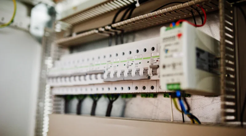
    This is why “load wire color” is a risky search query. A load wire does not have one universal color. It is often the same color family as other hot conductors, and its function must be confirmed by circuit position and testing, not color alone.


    What Is a Neutral Wire?

    A neutral wire is the grounded circuit conductor that provides the normal return path for current. In many single-phase AC circuits, current flows from the line conductor through the load and returns through the neutral conductor.

    Neutral is often near ground potential in a correctly wired system, but that does not make it harmless. A neutral conductor can carry load current. If a neutral connection opens, loosens, or is shared incorrectly, downstream equipment may behave unpredictably, and dangerous voltages may appear where users do not expect them.

    In practical terms:

    • Neutral completes the circuit during normal operation.
    • Neutral is not the same as ground.
    • Neutral should not be casually tied to ground at outlets, switches, or equipment.
    • Neutral may still be hazardous if the circuit is energized, miswired, or loaded.

    For a deeper explanation of voltage relationships, see VIOX’s guide to voltage vs current.


    What Is a Ground Wire?

    A ground wire, or equipment grounding conductor, is a safety conductor. It is not intended to carry normal operating current. Its job is to provide a low-impedance path for fault current so protective devices can operate during a fault.

    Ground and neutral are sometimes bonded at a defined point in the electrical system, such as the service equipment in many installations. That does not mean they are interchangeable downstream. In branch circuits and equipment wiring, using ground as neutral can create shock hazards and code violations.


    Line vs Load: The Most Common Source of Confusion

    The phrase line vs load does not mean “one color vs another color.” It means incoming side vs outgoing side of a device.

    Example Device Line Side Load Side
    Light switch Incoming hot feed Switched hot going to the light
    GFCI outlet Incoming supply from panel Downstream receptacles protected by the GFCI
    Circuit breaker Supply bus or source side Protected circuit conductor leaving the breaker
    Disconnect switch Incoming source Outgoing equipment feed
    Contactor Supply terminals Load terminals feeding motor, heater, or equipment

    A conductor can change labels depending on the device you are looking at. The wire leaving one switch may be the load wire for that switch, but when it reaches the next device, it may become that device’s line feed.

    That is why professional diagrams label terminals and direction clearly instead of relying only on wire color.


    Line and Load on a Switch

    Switch wiring diagram showing line in, load out, and neutral bypass to the light fixture.
    Switch wiring diagram showing line in, load out, and neutral bypass to the light fixture return path.

    In a simple single-pole switch circuit, the line conductor brings power into the switch, and the load conductor sends switched power to the lamp or equipment.

    Breaker hot conductor
            |
          LINE
       [ Switch ]
          LOAD
            |
         Light fixture
            |
         Neutral return
    

    In many traditional switch loops, the wiring may not look intuitive inside the wall box. A white conductor may be re-identified and used as an ungrounded conductor in certain wiring methods. That is one reason “white means neutral” is not enough for safe identification.

    If you are troubleshooting or replacing a switch, label conductors before disconnecting them and verify function with appropriate test equipment.


    Line and Load on a GFCI Outlet

    GFCI outlet line and load terminal wiring diagram with downstream protected receptacle.
    GFCI outlet line and load terminal wiring diagram showing incoming supply and downstream protected receptacle wiring.

    GFCI receptacles make line/load identification especially important.

    Terminal Function What Happens if Miswired?
    LINE Receives incoming power from the panel The device may not reset or may not provide expected protection
    LOAD Feeds downstream receptacles through the GFCI protection Downstream outlets may lose protection or power if connected incorrectly

    On a GFCI outlet, the line terminals are for the incoming supply. The load terminals are used only when you want the GFCI device to protect additional downstream outlets. If there is no downstream protection requirement, the load terminals may remain unused according to the device instructions.

    This is different from a standard receptacle, where terminals may simply pass power onward without built-in ground-fault protection.


    Line, Load, Neutral, and Ground in One Circuit

    Here is a practical way to visualize the four terms in a basic circuit:

    Panel / breaker
       |
       |  LINE hot conductor
       v
    [Switch or device]
       |
       |  LOAD hot conductor
       v
    [Lamp, outlet, or appliance]
       |
       |  NEUTRAL return conductor
       v
    Panel neutral bar / source return
    
    GROUND conductor connects metal enclosures and equipment grounding points for fault protection.
    

    Line and load describe the energized path through a device. Neutral describes the return conductor. Ground describes the safety bonding path.


    Line-to-Line vs Line-to-Neutral

    Some searches mix up wire identification with voltage measurement. Line-to-line and line-to-neutral describe voltage measured between conductors.

    Measurement What It Means Typical Use
    Line-to-neutral Voltage between one line conductor and neutral Single-phase loads, receptacles, lighting, control circuits
    Line-to-line Voltage between two line conductors Split-phase, three-phase, or higher-power loads
    Line-to-ground Voltage between line and equipment ground Useful for troubleshooting, but not a substitute for understanding neutral condition
    Neutral-to-ground Voltage between neutral and ground Should usually be low in a healthy circuit, but depends on load, wiring, and system design

    For example, in many North American residential systems, a common branch circuit may measure about 120 V line-to-neutral, while some larger loads use about 240 V line-to-line. In many other regions, line-to-neutral voltage may be around 230 V. Always follow the system voltage and local electrical standard for the specific installation.


    Wire Color Codes: Useful Clues, Not Final Proof

    Wire color can help, but it should never be the only identification method. Color conventions vary by country, age of installation, cable type, and whether conductors were re-identified.

    Function Common U.S. Color Clue Common IEC-Style Color Clue Caution
    Line / hot Black, red, blue, or other non-white/non-green colors Brown, black, gray depending on phase Must be verified; colors vary
    Neutral White or gray Blue Can still carry current
    Ground / protective earth Green or bare copper Green/yellow Should not be used as neutral
    Load hot Often same color family as hot conductors Often same color family as phase conductors No universal “load color” exists

    If a previous installer used nonstandard colors or failed to re-identify conductors, a color-based guess can be wrong. This is especially common in older homes, mixed wiring systems, control panels, and repaired circuits.


    How to Identify Line, Load, and Neutral Safely

    Safe workflow for identifying line, load, neutral, and ground wires using labels and a proper meter.
    Safe workflow for identifying line, load, neutral, and ground wires using device markings, labels, and a properly rated meter.

    The safe method depends on the circuit and local practice, but the general logic is:

    Step What a Qualified Person Checks Why It Matters
    1. Turn off and secure power before touching conductors Breaker, disconnect, lockout where required Prevents shock and accidental energization
    2. Inspect terminal labels LINE, LOAD, L, N, input, output, source, equipment markings Device markings are more reliable than assumptions
    3. Label wires before removing old devices Tape or tags Prevents losing line/load identity during replacement
    4. Use an appropriate tester or multimeter Confirm energized conductor and voltage relationship Identifies line, neutral, and ground function
    5. Test under safe conditions only Follow proper measurement category and meter safety rating Reduces measurement hazard
    6. Verify after wiring Correct operation, downstream protection, no abnormal heating or tripping Confirms the device works as intended

    Never use trial-and-error wiring on live circuits. If the wiring box contains multiple cables, shared neutrals, multi-way switching, aluminum conductors, or unclear old wiring, call a qualified electrician.


    Common Mistakes When Identifying Line, Load, and Neutral

    Mistake 1: Thinking Load Wire Means Neutral Wire

    A load wire is usually an outgoing energized conductor feeding the load. Neutral is the return conductor. They are not the same thing.

    Mistake 2: Assuming White Always Means Neutral

    White or gray is commonly used for neutral in many U.S. systems, but there are permitted and improper cases where a white conductor may be used differently. Always verify function.

    Mistake 3: Wiring GFCI Line and Load Backwards

    GFCI devices depend on correct line/load terminal use. Miswiring can cause reset problems, loss of downstream protection, or unexpected no-power conditions.

    Mistake 4: Treating Neutral as Safe to Touch

    Neutral can carry current and can become dangerous under open-neutral, shared-neutral, or miswired conditions. Treat all conductors as potentially energized until verified otherwise.

    Mistake 5: Using Ground as Neutral

    Ground is a safety conductor, not a normal current return path. Using ground as neutral can energize equipment grounding paths and create shock hazards.

    Mistake 6: Ignoring Device Markings

    Switches, breakers, GFCIs, RCBOs, contactors, and disconnects may have specific line/load or input/output markings. Always follow the product’s wiring diagram and instructions.


    Where Line and Load Matter in Electrical Products

    Line/load identification is not only a residential wiring issue. It matters in many VIOX product categories:

    • In MCB and breaker circuits, line and load markings help define source and protected circuit direction.
    • In RCBO circuits, correct live and neutral routing is important because the residual-current sensor must monitor the intended conductors.
    • In control panels, contactor line terminals and load terminals determine the correct power path to motors, heaters, or lighting circuits.
    • In surge protection, phase, neutral, and protective earth routing affect device selection and installation layout.

    The core rule is the same: read the device marking, confirm the wiring diagram, and verify the circuit before energizing.


    FAQ

    What is the difference between line and load?

    Line is the incoming power side of a device. Load is the outgoing side that feeds the connected equipment or downstream circuit. The terms are relative to the device being wired.

    Is load wire the same as hot wire?

    A load wire is often a hot conductor after a switch, breaker, GFCI, contactor, or other device passes power to the load. However, “load” describes the conductor’s position in the circuit, while “hot” describes an energized ungrounded conductor.

    What is a load wire on a switch?

    On a switch, the load wire is the switched conductor that leaves the switch and feeds the light or device. It is energized when the switch is ON and not energized through that switch when the switch is OFF.

    What is a neutral wire?

    A neutral wire is the grounded circuit conductor that carries return current back to the source during normal operation. It completes the circuit but should not be treated as harmless.

    What does a neutral wire do?

    Neutral provides the normal return path for current. In many AC circuits, current flows from line through the load and returns through neutral.

    What color is the load wire?

    There is no universal load wire color. In many systems, the load wire uses the same color family as hot conductors, such as black or red in U.S.-style wiring. Always identify it by circuit function and testing, not color alone.

    What color is line and neutral?

    In many U.S. systems, line or hot conductors are commonly black or red, and neutral is commonly white or gray. In many IEC-style systems, line conductors may be brown, black, or gray, and neutral is often blue. Local rules and existing wiring conditions must be checked.

    What is line-to-line vs line-to-neutral?

    Line-to-neutral is voltage measured between a line conductor and neutral. Line-to-line is voltage measured between two line conductors. Line-to-line voltage is commonly used for higher-power loads or multi-phase systems.

    What is line, load, neutral, and ground?

    Line brings power into a device. Load sends power out of the device to the connected load. Neutral returns current to the source. Ground provides a safety path for fault current and normally should not carry operating current.

    What is load and line in an MCB?

    In an MCB circuit, the line side is typically the supply side, and the load side is the protected outgoing circuit. Always follow the markings and wiring instructions for the specific breaker model, because terminal conventions and installation requirements can vary.


    Conclusion

    Line, load, neutral, and ground are not interchangeable terms. Line means incoming supply to a device. Load means outgoing power from that device. Neutral is the normal return conductor. Ground is the safety conductor for fault protection.

    For searchers trying to identify a wire, the most important lesson is this: do not rely on color alone. Use the device markings, understand the circuit role, and verify with proper test equipment. When the wiring is unclear, damaged, old, or tied into protective devices such as GFCI, RCBO, or breakers, the safe choice is to have a qualified electrician inspect it before energizing the circuit.

  • How Cable Lug Manufacturing Works: Complete Guide to Processes, Standards & Quality Control

    How Cable Lug Manufacturing Works: Complete Guide to Processes, Standards & Quality Control

    Cable lug manufacturing involves forging annealing copper or aluminum tubes through heavy power presses, followed by drawing processes that reduce diameter and wall thickness, then finishing with electro-tinning for corrosion resistance and optimal conductivity. Modern manufacturing combines traditional metalworking techniques with automated production systems to create reliable electrical connectors that meet stringent international safety standards.

    What Are Cable Lugs and Why Manufacturing Quality Matters

    all cable lug types

    VIOX Cable Lugs

    Cable lugs are devices used for connecting cable and wire conductors in electrical installations and equipment, where permanent, direct fastening methods are not feasible or necessary. These critical electrical components ensure safe, reliable connections between cables and electrical equipment across industries from automotive to power distribution.

    The stakes are high: Poor manufacturing quality can lead to increased joint resistance, overheating, and potentially catastrophic electrical fires. Wrong crimping tools or an incorrect crimp can result in increased joint resistance, increased temperatures, and even fire.

    Manufacturing Process Overview: From Raw Material to Finished Product

    Primary Manufacturing Methods Comparison

    Manufacturing Method Material Used Typical Applications Production Volume Quality Level
    Cold Forging Annealed copper tubes High-current applications High volume Premium
    Drawing Process Copper/aluminum tubes Standard electrical connections Medium-high volume Standard
    Stamping/Punching Flat copper/aluminum sheets Light-duty applications Very high volume Economy
    Precision Machining Solid copper bars Specialized/custom lugs Low volume Ultra-premium

    Step-by-Step Cable Lug Manufacturing Process

    cable lug Production workshop 7

    Phase 1: Raw Material Preparation

    1. Material Selection and Inspection
      • Source high-purity electrolytic copper (99.99% pure) according to EN 13600 standard
      • Inspect incoming materials for defects, composition, and dimensional accuracy
      • Verify material certificates and compliance documentation
    2. Tube Cutting and Sizing
      • Use automatic pipe cutting machines with servo motor control for precise length cutting
      • Maintain tight tolerances (±0.1mm) for consistent quality
      • Implement cooling systems to prevent heat-induced material changes

      Safety Warning: Always use proper ventilation when cutting copper materials to prevent inhalation of metal particles.

    cable lug Production workshop 3

    Phase 2: Primary Forming Operations

    1. Drawing Process for Tube Reduction
      • Pull hollow tubes through hardened steel dies of gradually decreasing diameter using 7-foot diameter bull block machines
      • Insert tapered plug mandrels inside tubes to control wall thickness and inner surface smoothness
      • Perform multiple drawing passes to achieve target dimensions
    2. Forging Operations
      • Use heavy power presses of various tonnage for forging annealed copper tubes
      • Apply controlled pressure to form lug heads and connection points
      • Maintain precise die alignment to prevent material flow defects

    cable lug Production workshop 2

    Phase 3: Finishing and Quality Control

    1. Chamfering and Deburring
      • Employ automatic double-head chamfering machines with PLC control systems for uniform edge finishing
      • Remove sharp edges that could damage cables during installation
      • Ensure smooth entry points for cable insertion
    2. Surface Treatment and Plating
      • Apply electro-tinning to ensure uniform coating for maximum conductivity and corrosion resistance
      • Measure plating thickness in microns using digital thickness meters
      • Verify coating uniformity and adhesion quality

    Expert Tip: Tin plating thickness should typically range from 5-15 microns for optimal performance and cost-effectiveness.

    Manufacturing Standards and Compliance Requirements

    International Standards for Cable Lug Manufacturing

    Standard Region Focus Area Key Requirements
    DIN 46235 Europe Compression cable lugs Electrolytic copper per EN 13600, specific crimping die requirements
    IEC 61238-1 International Electrical/mechanical properties 1000-cycle electrical durability test, mechanical tension testing
    UL 486A-486B North America Wire connectors safety Mechanical strength and electrical performance requirements
    EN 13600 Europe Copper material standards Seamless copper tubes for electrical purposes

    Mandatory Quality Control Checkpoints

    Material Quality Control

    • Raw Material Testing: Verify 99.99% pure copper composition
    • Dimensional Inspection: Check tube diameter, wall thickness, and length tolerances
    • Surface Quality: Inspect for cracks, inclusions, and surface defects

    Production Quality Control

    • Die Wear Monitoring: Regular inspection of forming dies for wear patterns
    • Dimensional Verification: Continuous measurement of critical dimensions
    • Visual Inspection: Check for burr-free surfaces, flat palms, and cleanly machined ends

    Finished Product Testing

    • Electrical Testing: Resistance measurement and current-carrying capacity verification
    • Mechanical Testing: Tension tests and connection durability assessment
    • Plating Quality: Thickness measurement and adhesion testing

    Safety Warning: All testing must be performed by qualified personnel using calibrated equipment to ensure accurate results and worker safety.

    cable lug Production workshop 8

    Advanced Manufacturing Equipment and Automation

    Modern Automated Production Systems

    Automatic cable lug machines consist of automatic stamping dies, vibration plates, and PLC controllers that control automatic feeding and punching operations. These systems offer several advantages:

    Key Automation Benefits:

    • Production Efficiency: Automated feeding systems and programmable settings enhance production efficiency and accuracy
    • Quality Consistency: Eliminates human variability in critical forming operations
    • Safety Improvement: Vibration plate automatic feeding reduces operational risk
    • Cost Reduction: Lower labor requirements and reduced material waste

    Equipment Selection Criteria

    When choosing cable lug manufacturing equipment, consider:

    1. Production Capacity: Match machine capacity (lugs per hour) to volume requirements
    2. Material Compatibility: Ensure equipment handles both copper and aluminum materials
    3. Automation Level: Semi-automatic, automatic, or fully automatic based on production needs
    4. Die Set Flexibility: Multiple die sets for different sizes and types including ring, fork, and non-insulated lugs

    Expert Tip: Invest in equipment with multiple die sets to maximize production flexibility and respond to varying market demands.

    Material Selection and Properties

    Copper vs. Aluminum Cable Lugs Comparison

    Property Copper Cable Lugs Aluminum Cable Lugs
    Electrical Conductivity Excellent (100% IACS) Good (61% IACS)
    Corrosion Resistance High Requires special coatings
    Weight Higher density Lightweight and cost-effective
    Cost Higher initial cost Lower material cost
    Durability Highly conductive and resistant to corrosion Requires oxidation compounds
    Applications High-load, critical applications Large-scale power distribution

    Specialized Material Options

    • Tinned Copper: Enhanced corrosion resistance for harsh environments, ideal for marine applications
    • Brass Lugs: Excellent resistance to corrosion, suitable for marine applications
    • Bi-metallic Lugs: Combination of conductivity and corrosion resistance

    Quality Assurance and Testing Procedures

    Mandatory Testing Requirements

    Electrical Performance Testing

    The international standard IEC 61238-1 specifies electrical durability tests where connections undergo 1000 heating cycles to approximately operating temperature. This ensures long-term safe operation.

    Mechanical Integrity Testing

    • Tension Testing: Verify mechanical strength of crimped connections
    • Vibration Testing: Assess performance under mechanical stress
    • Temperature Cycling: Evaluate thermal expansion/contraction effects

    Visual Quality Indicators

    High-quality cable lugs can be recognized by visual characteristics: burr-free cable lugs with flat palm and cleanly shaped ends are signs of a high-quality electrical connector.

    Quality Checklist:

    • Smooth, burr-free surfaces
    • Uniform tin plating without gaps or discoloration
    • Precise dimensional accuracy
    • Clean, well-defined connection points
    • No visible cracks or material defects

    Installation Considerations and Safety Requirements

    Proper Installation Techniques

    1. Cable Preparation: Strip insulation using specialized tools rather than knives or pliers to minimize wire strand damage
    2. Crimping Requirements: Use crimping tools with coded dies according to DIN 48083-4 for safe installation
    3. Compression Standards: Avoid over-compression which can damage conductors and increase electrical resistance

    Safety Warning: Over-compression can result in torn wires over time due to vibration, leading to higher electrical resistance and potential overheating.

    Professional Installation Requirements

    • Tool Calibration: Use hydraulic compression devices with regular calibration as recommended by manufacturers
    • Compatibility Verification: Select the correct lug for the conductor cross-section to prevent connection errors
    • Documentation: Maintain installation records for quality assurance and compliance

    Common Manufacturing Defects and Prevention

    Critical Defect Types

    Defect Type Causes Prevention Methods Quality Impact
    Surface Burrs Worn cutting dies, incorrect speeds Regular die maintenance, proper cutting parameters Poor cable insertion, potential damage
    Uneven Plating Poor surface preparation, contamination Clean pre-treatment, controlled plating conditions Reduced corrosion resistance
    Dimensional Variance Die wear, improper setup Precise die alignment, regular calibration Poor fit, connection reliability issues
    Material Inclusions Contaminated raw material Rigorou material inspection, certified suppliers Reduced electrical performance

    Prevention Strategies

    • Preventive Maintenance: Regular equipment inspection and die replacement schedules
    • Process Control: Statistical process control with real-time monitoring
    • Supplier Quality: Work with certified suppliers providing material traceability documentation

    Manufacturing Cost Considerations and Business Setup

    Initial Investment Requirements

    Start-up costs for cable lug manufacturing can range from tens of thousands to hundreds of thousands of dollars, depending on scale, location, equipment, and workforce requirements.

    Major Cost Components:

    • Manufacturing equipment (presses, drawing machines, automation)
    • Quality control and testing equipment
    • Raw material inventory
    • Facility setup and utilities
    • Skilled workforce training and certification

    Production Economics

    • Material Costs: Typically 40-60% of total manufacturing cost
    • Labor Costs: 15-25% (reduced with automation)
    • Equipment Depreciation: 10-20%
    • Quality Control: 5-10%
    • Utilities and Overhead: 10-15%

    Expert Tip: Consider manufacturing both copper and aluminum cable lugs to excel in the business, as both products are in high demand.

    Future Trends in Cable Lug Manufacturing

    Technology Advancement

    Artificial intelligence and machine learning are enhancing cable manufacturing efficiency through real-time process monitoring, predictive maintenance, and automated quality control.

    Emerging Technologies:

    • Smart Manufacturing: IoT-enabled machines communicate for seamless process coordination
    • Predictive Maintenance: AI systems predict equipment failures before they occur
    • Automated Inspection: AI-powered visual systems detect defects with greater accuracy than human operators

    Market Developments

    The global cable lug market is expected to grow significantly, driven by increasing demand for reliable electrical systems, with trends toward eco-friendly materials and smart cable lugs that detect potential issues in real-time.

    Frequently Asked Questions

    Q: What is the most critical factor in cable lug manufacturing quality?
    A: Material purity and proper electro-tinning are crucial, with 99.99% pure copper and uniform tin plating ensuring maximum conductivity and corrosion resistance.

    Q: How do you ensure consistent quality in high-volume production?
    A: Automated systems with PLC controllers, vibration plate feeding, and programmable settings provide consistent quality while reducing human error and operational risk.

    Q: What safety standards must cable lug manufacturers follow?
    A: Manufacturers must comply with IEC 61238-1 for electrical properties, UL 486A-486B for safety requirements, and DIN 46235 for European compression lug standards.

    Q: How is cable lug quality verified during production?
    A: Quality verification includes electrical durability testing with 1000 heating cycles, mechanical tension testing, and continuous monitoring of dimensional accuracy and surface quality.

    Q: What equipment is needed for automated cable lug manufacturing?
    A: Essential equipment includes automatic stamping dies, vibration plates, PLC controllers, hydraulic presses, and quality control systems with multiple die sets for production flexibility.

    Q: How do you prevent common manufacturing defects?
    A: Regular die maintenance, proper cutting parameters, controlled plating conditions, and rigorous material inspection prevent defects like surface burrs, uneven plating, and dimensional variance.

    Expert Recommendations for Manufacturers

    Quality Excellence Strategies

    1. Invest in Automation: Modern automated systems reduce defects and improve consistency
    2. Maintain Strict Standards: Implement comprehensive quality control with third-party testing when appropriate
    3. Focus on Material Quality: Source only certified, high-purity materials with full traceability
    4. Train Personnel: Ensure operators understand critical quality parameters and safety requirements
    5. Regular Calibration: Maintain all measurement and testing equipment to manufacturer specifications

    Business Success Factors

    • Market Diversification: Serve multiple industries to reduce dependency risk
    • Continuous Improvement: Implement Industry 4.0 technologies for data-driven process optimization
    • Compliance Focus: Stay current with evolving international standards and regulations
    • Customer Partnership: Work closely with customers to understand application-specific requirements

    Bottom Line: Success in cable lug manufacturing requires combining proven metallurgical processes with modern automation, strict quality control, and comprehensive safety compliance. Manufacturers who invest in proper equipment, maintain rigorous standards, and focus on continuous improvement will create products that ensure safe, reliable electrical connections for critical applications across industries.

    Related

    Top 10 Cable Lugs Manufacturers: Complete Industry Guide Updated 2025

    The Complete Guide to Cable Lugs: Types, Applications, and Installation Best Practices

    How to Choose the Right Copper Lug: A Comprehensive Guide