VIOX Electric
Language

Month: July 2025

  • Thermal Overload Relay Explained: Motor Protection, Working Principle, Contacts, and Selection

    Thermal Overload Relay Explained: Motor Protection, Working Principle, Contacts, and Selection

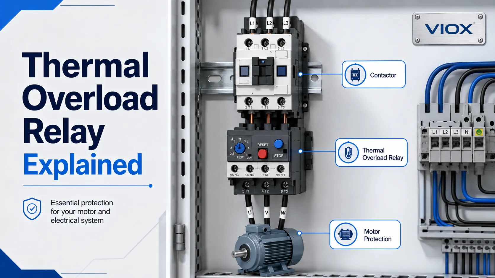
    A thermal overload relay is a motor protection device that trips when motor current stays too high for too long. It is designed to protect the motor from overload heating, not from short-circuit faults.

    In one sentence: a thermal overload relay opens the contactor control circuit when motor current remains above the set value long enough to create an overheating risk.

    In a typical motor starter, the contactor switches the motor on and off, while the thermal overload relay monitors motor current and opens the control circuit if the motor is overloaded. This prevents the motor from continuing to run under damaging thermal stress.

    The key point is simple: a thermal overload relay protects against sustained overload current; a fuse, MCB, MCCB, or MPCB is still required for short-circuit protection.

    Key Takeaways

    • A thermal overload relay protects motors from overheating caused by overload, locked rotor, long starting time, or phase-loss related overcurrent.
    • It normally works with a contactor. The overload relay trips the contactor coil circuit through a normally closed overload contact.
    • It does not replace short-circuit protection. You still need a suitable fuse, breaker, or motor protection circuit breaker upstream.
    • Selection depends on motor full-load current, trip class, reset mode, phase-loss sensitivity, contact arrangement, and contactor compatibility.
    • Common overload relay output contacts include a normally closed trip contact for stopping the contactor and a normally open auxiliary contact for alarm or signal use.

    Thermal Overload Relay at a Glance

    Item Practical Meaning
    Main function Protects a motor against sustained overload heating
    Protection type Time-delay thermal protection
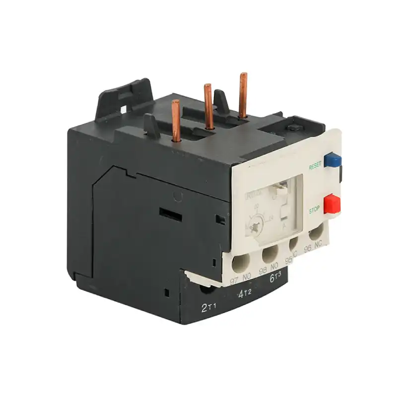
    Typical installation Between contactor and motor, or integrated with a motor starter assembly
    Main setting Current setting matched to motor full-load current
    Common trip contact NC contact opens the contactor coil circuit when overload occurs
    Reset modes Manual reset or automatic reset, depending on application
    Not designed for Clearing short-circuit current by itself
    Common standard context Motor starters and contactors are commonly handled under IEC 60947-4-1 or related market standards

    How a Thermal Overload Relay Works

    A thermal overload relay uses heat created by motor current to simulate motor heating. When the current remains above the set value long enough, the relay trips.

    The operating logic follows the motor’s thermal behavior:

    • small overloads should not trip instantly;
    • sustained overloads should trip after a delay;
    • severe overloads should trip faster;
    • normal starting current should be tolerated if it is within the selected trip class and motor starting profile.

    This is why a thermal overload relay is not an instantaneous device. It has an inverse-time behavior: the higher the overload current, the faster the trip.


    Why Thermal Overload Relays Trip Slowly

    A thermal overload relay trips slowly because motor damage is usually caused by heat accumulated over time, not by a momentary current spike. A motor may draw high current during starting, but that does not necessarily mean it is overloaded.

    The relay therefore uses a time-delay curve. It allows normal starting current for a limited time, but trips if the current remains above the setting long enough to overheat the motor. This is why trip class, starting time, and motor load type matter so much in selection.


    Bimetallic Thermal Overload Relay Working Principle

    The most common thermal overload relay design uses a bimetallic strip. A bimetallic strip is made from two metals with different thermal expansion rates. When current heats the strip, it bends. If the bending reaches the trip mechanism, the overload relay opens the trip contact.
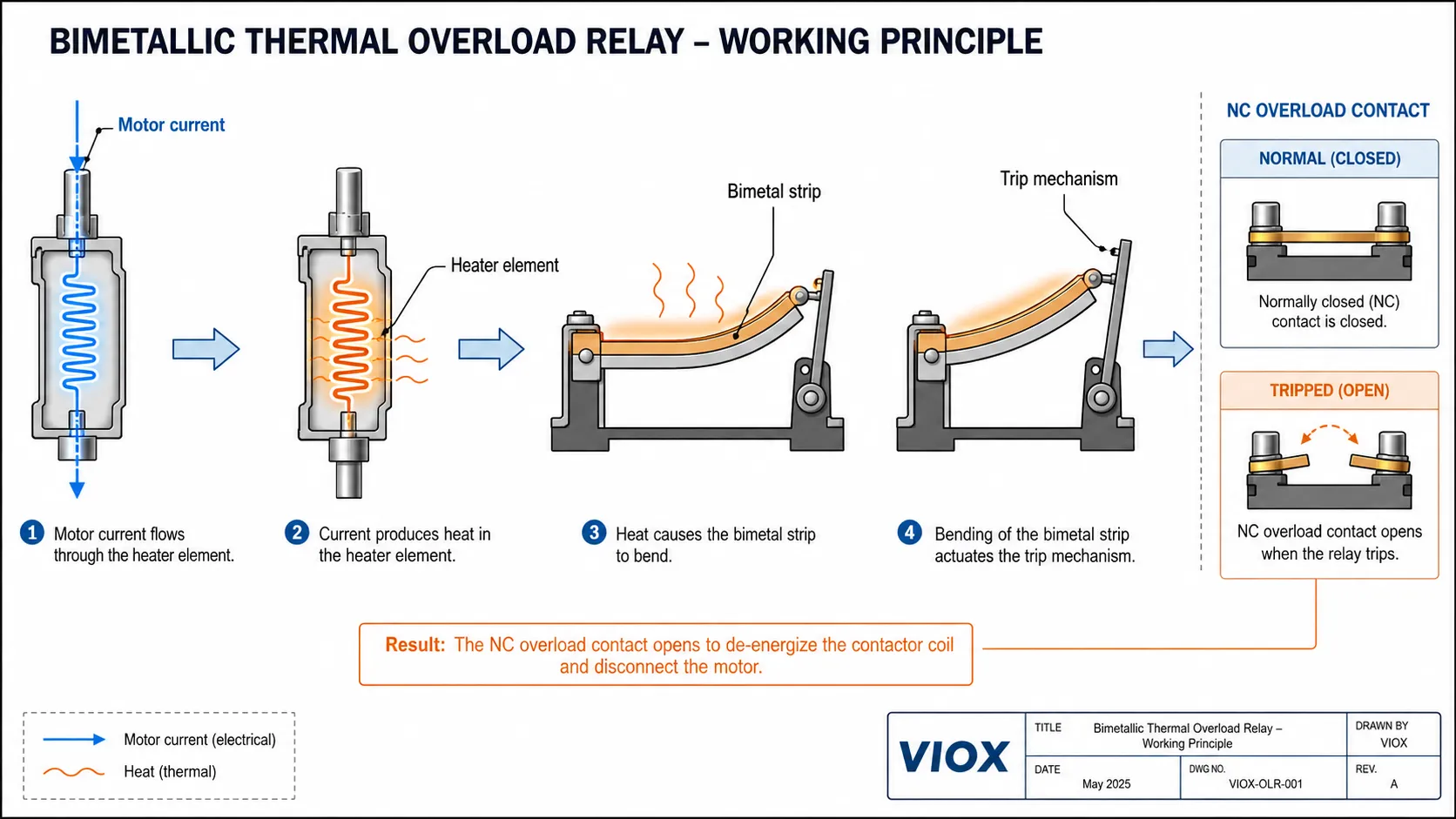
    Bimetallic thermal overload relay working principle showing heater element, bimetal strip, and trip contact.
    Bimetallic thermal overload relay working principle showing the heater element, bimetal strip, trip mechanism, and overload trip contact.

    In a motor starter, that trip contact is wired into the contactor coil circuit. When the contact opens, the contactor drops out and disconnects the motor from the power supply.

    This mechanical thermal memory is useful because motor damage is related to heat over time, not only to a single current value.


    Melting Alloy Thermal Overload Relay

    Some overload relays use a melting alloy, also called a eutectic alloy mechanism. In this design, overload current heats an element until a calibrated alloy melts or changes state, allowing the trip mechanism to operate.

    The purpose is still the same: convert sustained overcurrent into a delayed trip that reflects motor heating. The eutectic alloy provides a calibrated thermal element, so the relay trips only after the overload condition has produced enough heat.


    Thermal Overload Relay Contacts: NC, NO, and Overload Contact Function
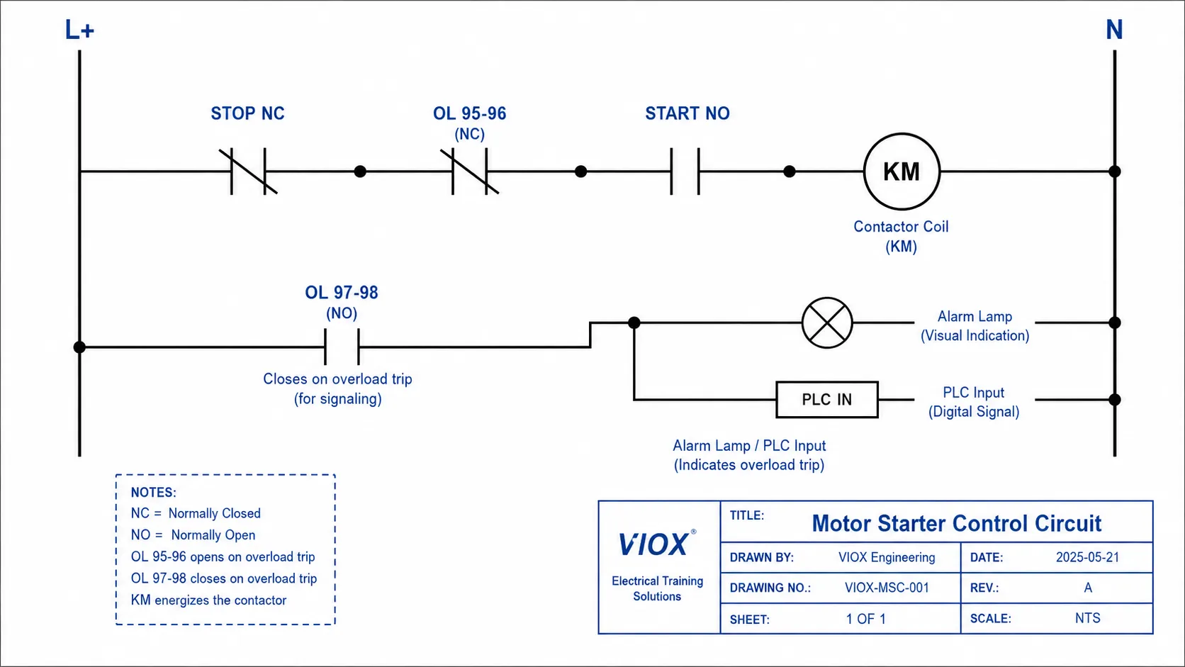
    Thermal overload relay ladder diagram with 95-96 NC trip contact and 97-98 alarm contact.
    Thermal overload relay ladder diagram showing the 95-96 normally closed trip contact and 97-98 normally open alarm contact.

    Most thermal overload relays provide at least one trip contact. In many IEC-style devices, the common convention is:

    Contact Common Terminal Marking Function
    Normally closed trip contact 95-96 Opens when the overload relay trips, breaking the contactor coil circuit
    Normally open signal contact 97-98 Closes when the relay trips, used for alarm, PLC input, or fault indication

    The exact markings and contact ratings must be checked on the device datasheet, but the control logic is usually the same: the NC overload contact stops the motor starter, and the NO contact reports the overload condition.

    Basic Contactor and Thermal Overload Relay Ladder Logic

    L+  ──[ STOP NC ]──[ OL 95-96 NC ]──[ START NO ]──( KM contactor coil )── N
                             |
                             +── opens on overload trip
    

    In a standard ladder diagram, the NC overload contact is placed in series with the contactor coil. When the overload relay trips, the 95-96 contact opens, the contactor coil loses power, the main contacts open, and the motor stops. The 97-98 NO contact, if used, can signal an alarm lamp or PLC input.

    For complete motor control selection, see VIOX’s guide to selecting contactors, overload relays, and circuit breakers for motor power.


    What Does a Thermal Overload Relay Protect?

    A thermal overload relay mainly protects the motor against overheating caused by excessive current over time.

    Condition Can Thermal Overload Relay Help? Notes
    Motor overloaded mechanically Yes Common use case
    Long starting time Yes, if trip class is selected correctly Incorrect trip class may cause nuisance tripping
    Locked rotor Often yes, within relay capability Short-circuit protection still required
    Phase loss / single phasing Some models provide sensitivity Do not assume every model handles phase loss equally
    Short circuit No, not by itself Requires fuse, MCB, MCCB, or MPCB
    Ground fault No, not by itself Requires suitable residual-current or ground-fault protection
    Motor winding temperature Indirectly Built-in thermal sensors provide more direct winding protection

    Ambient Compensation: Why Control Cabinet Temperature Matters

    Control cabinet temperature can affect thermal overload relay behavior. In a hot enclosure, the bimetal element may already be closer to its trip position before the motor current even rises. That can cause nuisance tripping in summer, near heaters, or inside densely packed panels.

    Ambient-compensated thermal overload relays use a compensating bimetal element to reduce the influence of surrounding air temperature. The protection element still responds to motor current heating, but the compensation mechanism helps keep the trip point more stable as cabinet temperature changes.

    This does not mean ambient temperature can be ignored. Panel builders should still check ventilation, enclosure temperature rise, contactor heat, cable sizing, and whether the overload relay’s ambient compensation range matches the installation conditions.


    Advantages and Limitations of Thermal Overload Relays

    Advantage Why It Helps
    Simple motor overload protection Easy to apply in standard contactor-based motor starters
    Time-delay behavior Tolerates normal motor starting current better than an instant trip device
    Adjustable current setting Can be matched to motor nameplate current within the relay range
    NC and NO auxiliary contacts Supports contactor trip control and alarm signaling
    Cost-effective for many standard motors Suitable for many pumps, fans, compressors, and machine motors
    Limitation Why It Matters
    No short-circuit protection by itself Must be coordinated with a fuse, breaker, or MPCB
    Limited diagnostics Mechanical thermal relays usually provide less fault information than electronic relays
    Selection depends on trip class Wrong trip class can cause nuisance trips or underprotection
    Phase-loss protection varies by model Do not assume all thermal overload relays detect phase loss equally
    Ambient temperature can affect behavior Check whether the relay has ambient compensation for cabinet conditions

    Thermal Overload Relay vs Short-Circuit Protection

    A thermal overload relay and a short-circuit protective device solve different problems.

    Device Main Protection Typical Response What It Protects
    Thermal overload relay Sustained overload current Delayed thermal trip Motor from overheating
    Fuse Short circuit and high fault current Very fast depending on fuse type Conductors and equipment against high fault current
    MCB / MCCB Overload and short circuit depending on type Thermal and magnetic/electronic trip Circuit conductors and equipment
    MPCB Motor overload and short-circuit protection depending on design Motor-specific protection Motor branch circuit

    Do not use a thermal overload relay as the only protective device in a motor circuit. It is normally part of a coordinated motor starter with short-circuit protection upstream.

    For broader fault terminology, see Overload vs Overcurrent vs Short Circuit.


    IEC 60947-4-1 Type 1 vs Type 2 Coordination
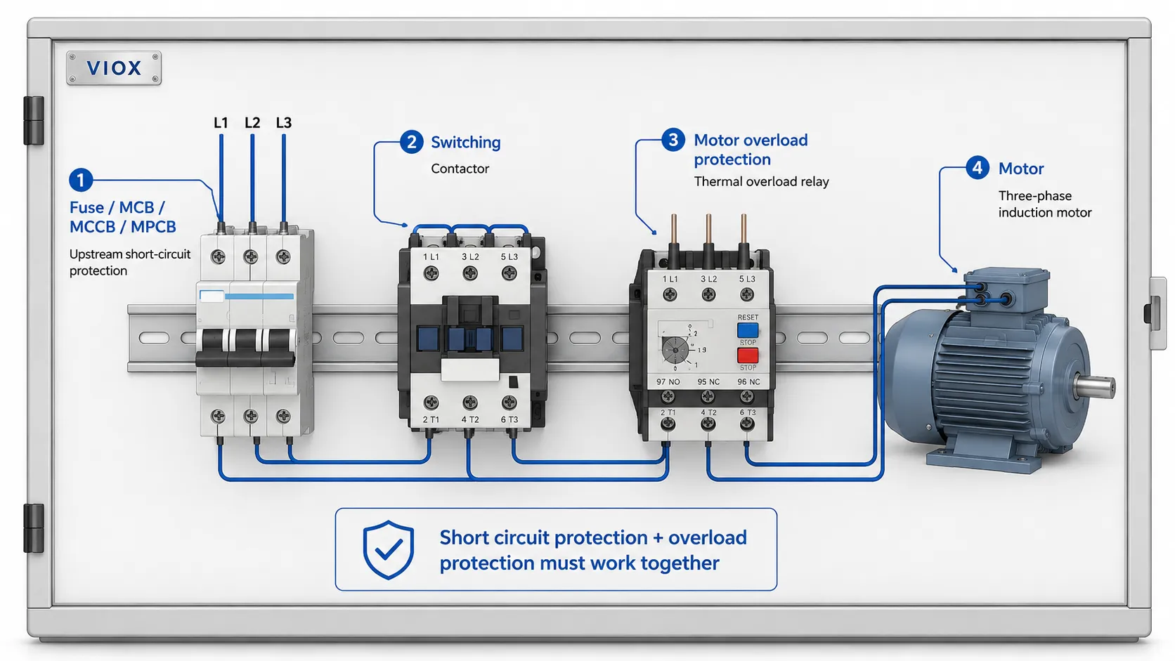
    Motor starter coordination diagram showing breaker, contactor, thermal overload relay, and motor protection path.
    Motor starter coordination diagram showing how the breaker, contactor, thermal overload relay, and motor protection path work together.

    When a thermal overload relay is used with a contactor and short-circuit protective device, engineers also need to consider starter coordination. In IEC 60947-4-1 context, Type 1 and Type 2 coordination describe what condition the starter is allowed to be in after a short-circuit test.

    Coordination Type Practical Meaning Why It Matters
    Type 1 coordination The starter must not create danger, but components may need repair or replacement after the fault Lower cost, but downtime and replacement may be expected
    Type 2 coordination The starter must remain suitable for further service after the fault, with limited contact welding allowed under defined conditions Higher availability and better for critical machinery

    This is not a rating that the overload relay provides alone. It depends on the tested combination of contactor, overload relay, and upstream short-circuit protective device. For OEM panels and industrial machines, asking only for the overload relay current range is not enough; the complete motor starter combination should be checked.


    Thermal Overload Relay Trip Class: Class 10, Class 20, and Class 30
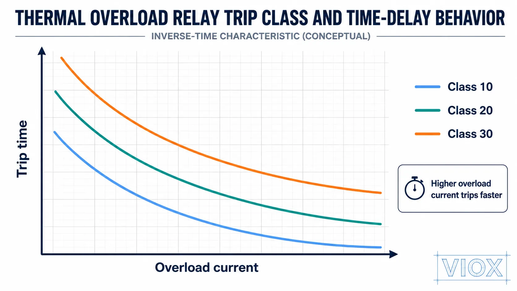
    Thermal overload relay trip class chart showing Class 10, Class 20, and Class 30 inverse-time curves.
    Thermal overload relay trip class chart showing Class 10, Class 20, and Class 30 inverse-time trip behavior for different motor starting profiles.

    Trip class describes how quickly the overload relay trips under defined overload test conditions. Common classes include Class 10, Class 20, and Class 30.

    Trip Class Typical Use Selection Caution
    Class 10 Standard motors with normal starting time Too low for heavy-start loads may cause nuisance trips
    Class 20 Motors with longer acceleration time Must still protect the motor from excessive heating
    Class 30 Heavy-start applications with long acceleration Requires careful motor and starter coordination

    Do not choose a higher trip class just to stop nuisance tripping. If the motor is tripping during startup, check starting current, acceleration time, motor load, supply voltage, mechanical load, and whether the starter and overload relay are correctly selected.


    How to Select a Thermal Overload Relay

    Selection Factor What to Check Why It Matters
    Motor full-load current Match the relay setting range to the motor nameplate current The relay must be adjustable to the actual motor FLA
    Contactor compatibility Mechanical and electrical fit with the contactor Many overload relays mount directly under matching contactors
    Trip class Class 10, 20, 30, or manufacturer-specific class Must match motor starting profile
    Phase-loss sensitivity Whether the relay detects unbalanced heating or phase loss Important for three-phase motor protection
    Reset mode Manual or automatic Manual reset is safer for many machines
    Auxiliary contacts NC trip contact and NO alarm contact Needed for contactor control and signaling
    Ambient compensation Whether temperature changes affect trip behavior Useful in control cabinets and warm environments
    Coordination with short-circuit device Fuse, MCB, MCCB, or MPCB Prevents unsafe fault clearing arrangements

    For motor starter architecture, VIOX also covers MCB + contactor + overload relay vs MPCB + contactor.


    Manual Reset vs Automatic Reset

    Thermal overload relays may support manual reset, automatic reset, or both depending on the model.

    Reset Mode Meaning Best Use
    Manual reset A person must reset the relay after trip Safer for machinery where automatic restart could be dangerous
    Automatic reset Relay resets after cooling Used only where automatic restart is safe and allowed

    For motor-driven machinery, automatic reset can be risky. If the motor restarts unexpectedly after cooling, it may create mechanical or personnel hazards. Always follow machine safety requirements and local code.


    Thermal Overload Relay vs Built-In Motor Thermal Protector

    Some motors include inherent motor protection such as thermal switches, thermistors, or embedded temperature sensors. These devices are built into the motor and respond more directly to winding or internal motor temperature.

    Protection Method Where It Is Located What It Detects Best Typical Role
    Thermal overload relay Motor starter or control panel Current-related motor heating External overload protection and contactor trip control
    Built-in thermal protector Inside the motor Internal winding or motor temperature Direct motor temperature protection
    Motor thermistor / sensor Embedded in motor winding Actual winding temperature trend Used with a protection relay or drive input

    Built-in motor protection does not automatically remove the need for branch-circuit protection or starter overload coordination. In many systems, internal motor protection and external overload protection work together.


    Thermal Overload Relay vs Electronic Overload Relay

    A thermal overload relay is simple, robust, and widely used. An electronic overload relay uses sensors and electronics to monitor current and may offer more adjustable protection functions.

    Feature Thermal Overload Relay Electronic Overload Relay
    Sensing principle Thermal bimetal or melting alloy Current sensing and electronic logic
    Adjustment Usually simple current setting Often wider and more precise settings
    Phase loss protection Depends on model Often stronger and more configurable
    Diagnostics Limited May include alarms, trip memory, communication, or display
    Cost Usually lower Usually higher
    Best fit Standard motor starter applications Higher-value motors, process equipment, diagnostics-heavy systems

    If the motor is critical, expensive, difficult to access, or part of a process line, electronic overload protection may justify the additional cost.


    Thermal Overload Relay vs Thermal-Magnetic Breaker

    The phrase thermal magnetic overload relay is often used loosely, but it can be misleading.

    A thermal overload relay is a motor overload protection device. A thermal-magnetic breaker is a circuit breaker with thermal and magnetic trip elements. The breaker protects the circuit against overload and short circuit, while the overload relay is focused on motor thermal protection and contactor control.

    In many motor circuits, both are needed: a short-circuit protective device upstream and an overload relay matched to the motor.


    Thermal Overload Relay Symbol and Wiring Diagram Notes

    In electrical drawings, a thermal overload relay is usually shown as an overload protection element associated with the motor starter. The trip contact is commonly shown as a normally closed auxiliary contact in the contactor coil circuit.

    When reading a motor starter diagram, look for:

    • the overload relay power path between contactor and motor;
    • the NC overload trip contact in series with the contactor coil;
    • the NO alarm contact if connected to a PLC or indicator;
    • reset mode and trip indication.

    This is why the overload relay appears in both the power circuit and the control circuit: it senses motor current in the power path and interrupts the control circuit when it trips.


    Troubleshooting: Why a Thermal Overload Relay Keeps Tripping

    Repeated thermal overload trips usually mean the motor is overheating, the starter is misapplied, or the relay is set incorrectly. Do not simply increase the current setting to keep production running.

    Symptom Likely Cause What to Check
    Trips during motor startup Trip class too low, starting time too long, low voltage, heavy mechanical load Motor acceleration time, supply voltage, load inertia, Class 10 vs Class 20/30 suitability
    Trips after running for several minutes Mechanical overload, bearing problem, blocked fan, pump overload Load current on each phase, mechanical resistance, cooling airflow
    Trips mainly in hot weather Cabinet temperature rise or poor ventilation Enclosure temperature, spacing, contactor heat, ambient compensation
    Trips on one motor but not another Wrong current setting or relay range Motor nameplate FLA, relay dial setting, CT ratio if used
    Trips after phase loss or imbalance Supply issue or phase-loss condition Phase voltage, phase current balance, upstream fuse/breaker condition
    Trips but contactor does not drop out NC overload contact not wired correctly 95-96 contact in series with coil circuit, wiring continuity

    Field note: when a motor trips during startup, replacing a Class 10 overload relay with Class 20 may solve nuisance tripping only if the motor and starter are rated for the longer start. A better check is to measure actual starting current, acceleration time, phase voltage, cable voltage drop, and mechanical load before changing the trip class.


    Common Selection and Wiring Mistakes

    Mistake 1: Treating the overload relay as short-circuit protection

    The overload relay protects against sustained thermal overload. It does not safely clear high short-circuit current by itself.

    Mistake 2: Setting the current too high to avoid nuisance trips

    Increasing the setting can hide a real overload and leave the motor underprotected. First check mechanical load, voltage, starting time, and trip class.

    Mistake 3: Ignoring the motor nameplate current

    The overload relay should be set according to the motor nameplate and applicable design rules, not guessed from motor horsepower alone.

    Mistake 4: Using automatic reset in unsafe machinery

    Automatic restart after cooling may be dangerous. Manual reset is often preferred where unexpected motion can create a hazard.

    Mistake 5: Forgetting the NC overload contact

    If the NC trip contact is not wired in series with the contactor coil, the overload relay may trip mechanically but fail to stop the motor starter as intended.


    FAQ

    What is a thermal overload relay?

    A thermal overload relay is a motor protection device that trips when motor current stays above the setting long enough to create overheating risk. It is used with a contactor in many motor starters.

    What does an overload relay do?

    It monitors motor current and opens a control contact when the motor is overloaded. This de-energizes the contactor coil and stops the motor.

    Does a thermal overload relay protect against short circuit?

    No. A thermal overload relay is not a short-circuit protective device. Use a suitable fuse, breaker, or MPCB for short-circuit protection.

    What is the function of an overload contact?

    The overload contact changes state when the overload relay trips. The normally closed contact is typically used to open the contactor coil circuit, while the normally open contact can be used for alarm or PLC signaling.

    What is a thermal relay?

    A thermal relay is another common name for a thermal overload relay. In motor control, it usually means a device that trips based on heat produced by sustained current.

    What is thermal overload protection?

    Thermal overload protection prevents motors or equipment from running too long under excessive current. It is time-delayed because heating damage depends on current and time.

    What is a melting alloy thermal overload relay?

    It is an overload relay that uses a calibrated alloy mechanism that changes state when heated by overload current. This thermal action trips the relay.

    What do thermal overload relays protect in a motor circuit?

    They mainly protect the motor from overheating caused by sustained overload current. They do not replace short-circuit, ground-fault, or residual-current protection.

    Are inherent motor protection devices built into the motor?

    Yes. Inherent motor protection devices are built into the motor, such as thermal sensors or protectors. Their reset behavior depends on the device design, so do not assume every motor resets the same way.


    Related VIOX Resources


    Conclusion

    A thermal overload relay is a core motor protection device. It monitors sustained overload current, trips with a time-delay behavior that reflects motor heating, and opens the contactor control circuit to stop the motor.

    For correct selection, match the relay to the motor full-load current, trip class, contactor frame, reset mode, phase-loss requirements, auxiliary contacts, and upstream short-circuit protection. The best motor starter design treats the thermal overload relay as one part of a coordinated protection system, not as a standalone answer to every motor fault.
  • 3 Phase Isolator Switch: 3P vs 4P, Ratings and Wiring

    3 Phase Isolator Switch: 3P vs 4P, Ratings and Wiring

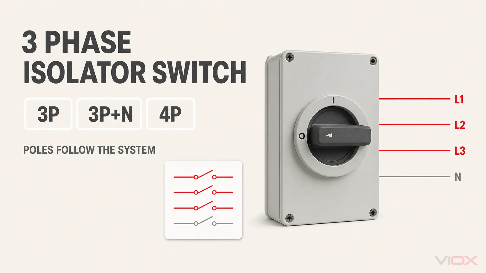
    A 3 phase isolator switch operates multiple poles together to separate a three-phase circuit from its source. Use a 3-pole arrangement when the design requires L1, L2, and L3 to be disconnected while the neutral is absent or remains connected. Consider 3P+N or 4P only when the system design and applicable rules require the neutral to be switched.

    Pole count does not prove load-breaking capability. A disconnector provides isolation but may not be intended to open normal load current. A switch-disconnector provides isolation plus its declared making and breaking duty. Before choosing either device, verify its rated operational voltage (Ue), rated operational current (Ie), utilization category, contact diagram, neutral-pole behavior, short-circuit coordination, and installation conditions.

    First decision What to verify
    Isolation only or normal load switching? Disconnector versus switch-disconnector function
    Three phases only or three phases plus neutral? 3P, 3P+N, or 4P contact arrangement
    May the neutral be interrupted? Earthing system, source architecture, local rules, and equipment requirements
    Is there a PEN conductor? Do not place the PEN in the switching path under the applicable TN-C rules
    Motor, mixed, or resistive load? Ie at Ue under the required utilization category
    Can the switch clear a fault? No assumption: coordinate it with the specified upstream short-circuit protective device

    If you need a general introduction before applying these decisions to a three-phase system, start with what an isolator switch is.

    Where a 3 Phase Isolator Sits in the System

    The system boundary is more important than the handle shape. In a typical low-voltage circuit, the device is placed between a source-side protective arrangement and the equipment or distribution section that must be isolated.

    Three-phase source
            │
    Upstream fuse or circuit breaker (fault protection)
            │
    3P / 3P+N / 4P disconnector or switch-disconnector
            │
    Three-phase load or downstream distribution
    
    Protective earth (PE): continuous protective path; not a switched pole
    Neutral (N): switched only when the system design and applicable rules require it

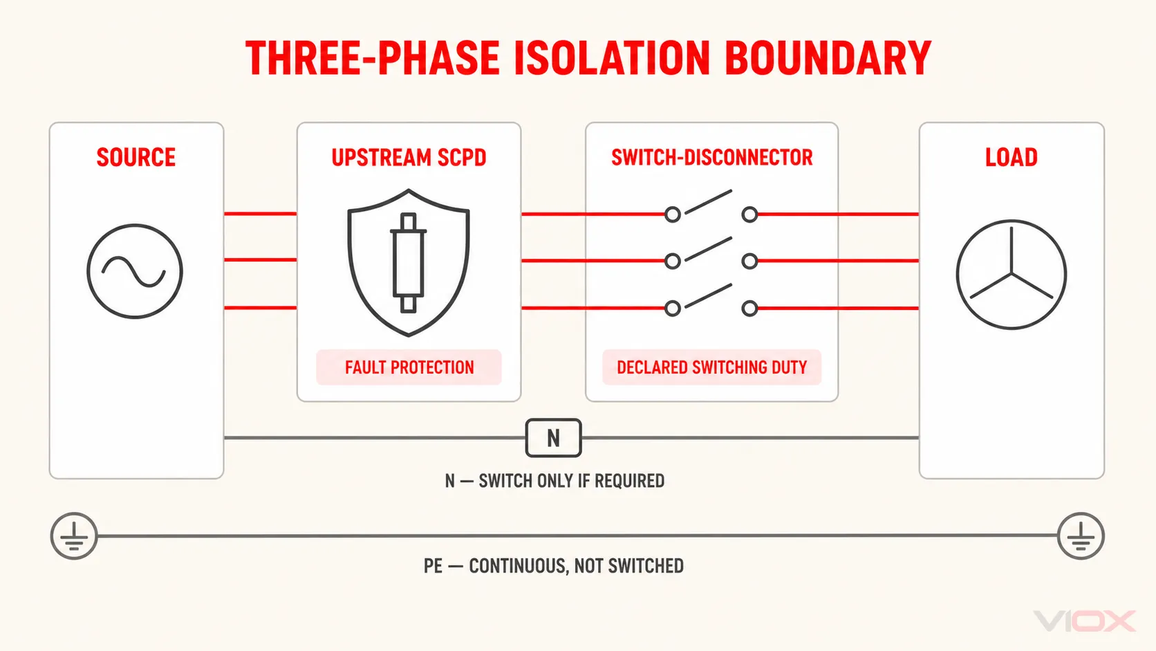
    Three-phase isolation boundary showing the upstream SCPD, switch-disconnector, load, optional neutral path, and continuous protective earth

    This is a functional diagram, not a terminal-level wiring instruction. Terminal locations, line/load orientation, pole-series arrangements, auxiliary contacts, and tightening requirements must come from the exact product instructions and approved project drawing.

    The isolating device does not replace overcurrent or short-circuit protection. Its upstream short-circuit protective device (SCPD) must be selected and coordinated for the circuit and any conditional short-circuit declaration. The separate circuit breaker vs isolator switch guide explains that protection boundary in more detail.

    Disconnector or Switch-Disconnector?

    “Three phase isolator switch” is a market term, not enough information for engineering selection. Convert it into the required function.

    Device function Isolation function Normal load switching Fault interruption
    Disconnector Yes, within its declared isolation conditions Do not assume; verify the declaration No automatic overcurrent interruption
    Switch-disconnector Yes Yes, within its Ue, Ie, utilization category, and operating conditions No automatic overcurrent interruption
    Fuse switch-disconnector Isolation and switching as declared As declared for the complete arrangement Integrated fuses may provide protection when correctly selected and coordinated

    IEC 60947-3:2020+AMD1:2025 covers switches, disconnectors, switch-disconnectors, and fuse-combination units within its stated low-voltage scope. That product-standard family distinguishes isolation, switching, withstand, making, and protection functions; the word “isolator” alone does not establish all of them.

    A four-pole product can be a load-switching device. For example, Hager publishes a specific four-pole load-break switch with declared AC-21, AC-22, and AC-23 operational ratings. This example demonstrates the principle only: four poles does not mean off-load only. It does not transfer that model’s ratings to another product.

    For a deeper terminology map, see isolator vs disconnector vs switch-disconnector.

    3-Pole vs 4-Pole Isolator Switch: Should the Neutral Be Switched?

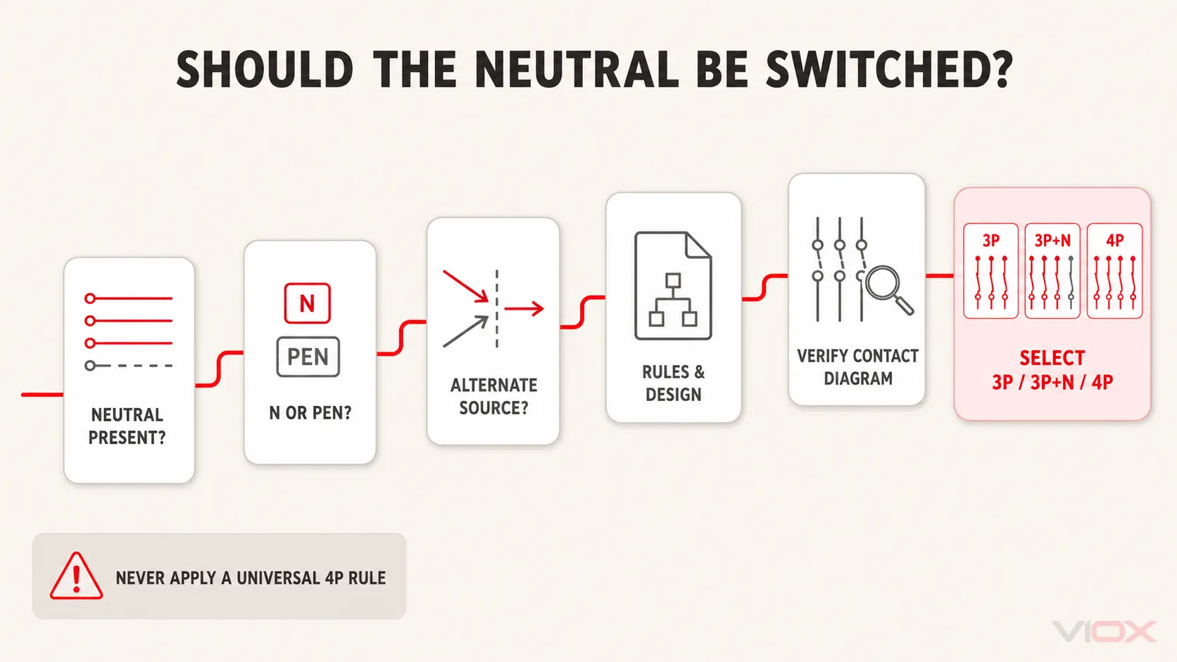
    Do not begin with “3P or 4P?” Begin with the conductors and sources in the circuit. Determine whether a neutral exists, whether it is N or PEN, whether alternate sources can keep it energized or establish another reference, and what the applicable rules require.

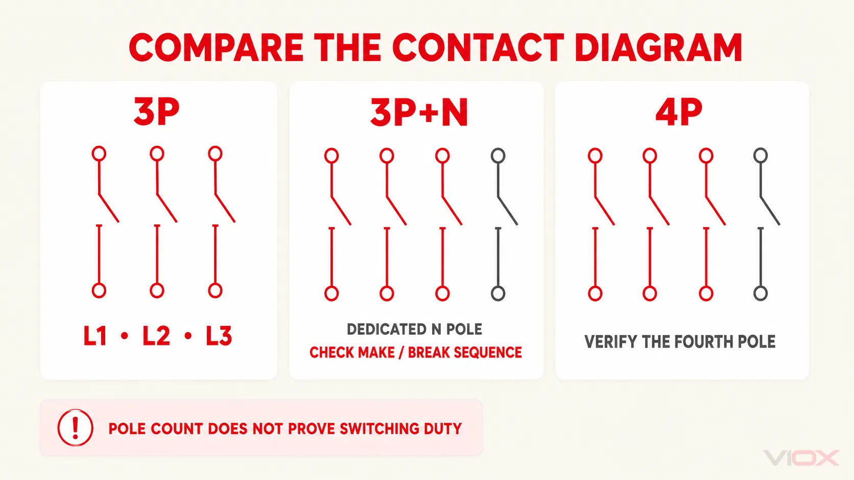
    Arrangement Conductors controlled Where it may fit What must be verified
    3P L1, L2, L3 Three-wire motor or other circuit with no distributed neutral; systems where the neutral is not required to be switched Earthing system, absence or treatment of neutral, control-power path, and local rules
    3P+N Three phase poles plus a dedicated N pole Four-wire systems requiring coordinated neutral switching N marking, neutral-pole rating, contact sequence, and manufacturer diagram
    4P Four operated poles Three-phase four-wire distribution, transfer, or other architectures requiring all four declared poles Function of the fourth pole, equal or reduced rating, contact sequence, diagram, and applicable rules
    Application-specific 4P DC DC conductors or series contact paths Some photovoltaic, battery, or DC distribution products Explicit DC Ue, Ie, utilization category, polarity, series path, and manufacturer instructions

    Conceptual comparison of 3P, 3P+N, and 4P isolator or switch-disconnector contact arrangements

    3P+N Is Not Automatically the Same as 4P

    The fourth path may not behave like a phase pole. It can be identified as a neutral pole and may have a defined operating sequence. Schneider Electric’s model-specific 3P+N switch-disconnector guidance describes an N pole that closes before and opens after the phase poles to reduce the risk of a floating neutral in that product arrangement.

    That behavior must not be assumed for every 3P+N or 4P device. Check:

    • the product’s contact diagram;
    • whether the fourth pole is marked N;
    • whether it closes first and opens last, or operates simultaneously;
    • the operational and thermal rating of the neutral pole;
    • whether the accessory and handle operate all required poles together; and
    • the manufacturer’s permitted connection arrangement.

    Neutral Switching Depends on the System

    There is no safe global rule that every three-phase circuit must use four-pole isolation. Schneider Electric’s engineering discussion of three- versus four-pole switching illustrates several important boundaries in a Dutch NEN 1010 context:

    • a PEN conductor in the cited TN-C arrangement must not be interrupted;
    • some TN-S situations may use three-pole separation, while others require the neutral to be included;
    • TT circuits and downstream distribution can impose different neutral requirements; and
    • a UPS or another source architecture can make neutral treatment more complex than simply adding a fourth pole.

    These examples are not a global wiring rule. They show why the designer must identify the earthing arrangement, every source, the neutral reference, and the applicable national rules before specifying the pole arrangement.

    Seven Questions for the 3P/3P+N/4P Decision

    Use this sequence before comparing product codes.

    1. Does the load or downstream section use a neutral? A three-wire motor circuit and a four-wire distribution circuit do not have the same conductor set.
    2. Is the conductor a neutral (N) or a combined protective and neutral conductor (PEN)? Do not treat these as interchangeable.
    3. What does the applicable installation rule require or prohibit? Record the jurisdiction and the specific project interpretation.
    4. Are there alternate sources or parallel paths? Check generators, uninterruptible power supplies (UPS), automatic transfer switches (ATS), inverters, and backfeed paths.
    5. Is the proposed device 3P+N or 4P? Read the marking and contact diagram rather than relying on the catalog title.
    6. How does the neutral pole operate? Verify first-make/last-break or other declared sequencing, plus the fourth-pole rating.
    7. Does the device have the required switching duty? Pole count does not replace the Ue, Ie, utilization-category, and coordination checks.

    Neutral-switching decision flow covering neutral presence, N versus PEN, alternate sources, applicable rules, and the exact contact diagram

    If any answer is unknown, pause the part-number selection. A larger ampere rating cannot correct an unsuitable neutral strategy.

    How to Read a 3 Phase Isolator Wiring Diagram

    A useful conceptual diagram should show functions, not pretend that every model has the same terminal numbering.

    Diagram item What it should establish What it cannot prove by itself
    L1, L2, L3 paths All required phase poles operate together Exact terminal location or phase sequence at a specific product
    Optional N path Whether the neutral passes through a dedicated or fourth pole Whether switching the neutral is required or permitted in the project
    PE path Protective earth remains a continuous protective connection Bonding details for the complete installation
    Upstream SCPD Fault protection is outside the basic isolator function Coordination without the exact fuse/breaker and conditional-rating data
    Contact state The diagram’s defined unoperated/open/closed condition Safe isolation of an installed circuit without an approved verification procedure

    Never infer a connection by enclosure appearance. Two rotary devices can share the same handle and housing while having different pole diagrams, utilization categories, line/load conventions, or DC/AC declarations. For AC-versus-DC suitability, use the dedicated DC isolator vs AC isolator switch comparison.

    Installation and verification must be performed by appropriately qualified personnel using the approved project drawing, the exact manufacturer’s instructions, and the applicable rules. Moving a handle to OFF is not, by itself, a complete safe-isolation procedure.

    Ratings That Must Match the Three-Phase Application

    The front current value is only one field. A defensible specification links each rating to the actual circuit and duty.

    Rating or declaration Selection question Common error
    Device function Is it a disconnector, switch, or switch-disconnector? Assuming every “isolator” can break load current
    Ue — rated operational voltage Is the AC operational voltage suitable for the system? Using Ui as the normal operating voltage
    Ie — rated operational current Is Ie adequate at the required Ue and utilization category? Selecting from the largest ampere marking only
    Utilization category Does the declared category match resistive, mixed, or motor/highly inductive duty? Treating AC-21 and AC-23 values as interchangeable
    Operating suffix Is the A/B duty declaration appropriate where stated? Ignoring operating-frequency conditions
    Poles and contact behavior Does the diagram match L1/L2/L3/N treatment? Treating 3P+N and 4P as universal equivalents
    Icw and Icm Can the device withstand and make the declared short-circuit currents under the specified conditions? Treating withstand or making capacity as automatic interruption
    Conditional short-circuit rating Is the exact upstream SCPD and arrangement documented? Using the rating with a different fuse or breaker
    Enclosure and operator Does the complete assembly meet access, lockability, environment, and mounting needs? Assigning the enclosure’s IP claim automatically to a modified assembly
    Market evidence Does the exact model have the required certificate and instructions? Inferring approval from a family brochure or logo

    Utilization Categories for Common AC Duties

    For IEC-oriented switch-disconnectors, utilization category is part of the operational rating:

    • AC-20: connecting or disconnecting under no-load conditions;
    • AC-21: resistive loads, including moderate overloads;
    • AC-22: mixed resistive and inductive loads, including moderate overloads; and
    • AC-23: motor loads or other highly inductive loads.

    Use the manufacturer’s exact table at the project voltage. A device can have different Ie values across utilization categories, and an enclosure, ambient condition, terminal arrangement, or operating frequency can further limit the usable declaration. The broader isolator switch selection guide provides a complete input-to-specification workflow.

    Short-Circuit Coordination Is a Separate Gate

    A switch-disconnector can have rated short-time withstand current (Icw), rated short-circuit making capacity (Icm), and a conditional short-circuit rating when protected by a specified SCPD. None of those declarations means the switch automatically detects and clears an overload or short circuit.

    Record the prospective short-circuit current, the exact upstream fuse or circuit breaker, the switch’s declared ratings, and every condition attached to the combination. IEC identifies conditional short-circuit requirements for switches and disconnectors protected by circuit breakers within the current IEC 60947-3 publication framework.

    Three Bounded Application Examples

    Three-Wire Motor Circuit

    A motor circuit with L1, L2, and L3 and no distributed neutral may use a 3P arrangement when the system design and applicable rules support it. If the device will routinely make or break motor current, verify a switch-disconnector rating for the required motor/highly inductive duty—typically the relevant AC-23 declaration—rather than selecting an isolation-only device from its ampere value.

    Four-Wire Distribution Circuit

    A downstream board or mixed-load circuit may include L1, L2, L3, and N. Whether the neutral must be disconnected depends on the earthing arrangement, source and downstream architecture, applicable rules, and the approved design. If the neutral is switched, confirm whether the product is 3P+N or 4P, how the N pole is rated and sequenced, and whether all relevant sources are isolated.

    Generator, UPS, ATS, or Inverter System

    Alternate-source systems require a source-and-neutral diagram before selecting the switch. A neutral may be common, switched, separately derived, or referenced elsewhere depending on the architecture. A generic rule such as “always use 4P” can create an unintended floating reference or fail to isolate an alternate path. The engineer should resolve source bonding, neutral treatment, transfer sequence, and protective-device coordination before choosing the pole configuration.

    Copy-Ready 3 Phase Isolator Specification Record

    Complete this record before requesting a part number or quotation.

    Specification field Project entry
    Required function [Disconnector / switch-disconnector / fuse switch-disconnector]
    System [Three-phase three-wire / three-phase four-wire / alternate-source architecture]
    Earthing and neutral arrangement [System type], [N or PEN], [neutral-switching decision authority]
    Supply [AC voltage], [frequency]
    Load duty [Resistive / mixed / motor or highly inductive / defined application]
    Operational rating Ie ≥ [required value] at Ue [value] under [utilization category]
    Pole arrangement [3P / 3P+N / 4P], contact diagram required
    Neutral-pole behavior [N marking], [rating], [make/break sequence], or not applicable
    Short-circuit coordination [Prospective current], [upstream SCPD], [Icw/Icm/conditional data]
    Construction [DIN rail / panel / door coupled / enclosed], [handle/shaft/interlock/lock]
    Environment [Complete-assembly IP/NEMA need], [ambient/altitude/corrosion conditions]
    Market documents [Destination], [standard/approval], exact model documents required

    Short Answers to Common 4-Pole Questions

    Is a 4 pole isolator required for every three-phase system?

    No. Use a four-pole arrangement only when the circuit architecture, neutral treatment, applicable rules, and equipment requirements call for the neutral or fourth conductor to be switched. A three-wire load with no neutral can have a different requirement.

    Can a 4 pole isolator be used for a single-phase circuit?

    Only when the exact manufacturer’s documentation permits the proposed poles and connection arrangement and the device has suitable operational ratings. Do not parallel unused poles or invent a connection to increase current or voltage capability.

    Is 3P+N the same as 4P?

    Not necessarily. A 3P+N device can have a dedicated neutral pole with different marking, rating, or first-make/last-break behavior. A 4P label also does not prove that all four poles are identical. The contact diagram and datasheet decide.

    Does a 4 pole isolator provide overload protection?

    Not by pole count. A basic disconnector or switch-disconnector does not automatically detect overcurrent. Protection must come from the correctly selected and coordinated protective arrangement unless the product is a documented fuse-combination or protective device.

    From System Record to Product Evaluation

    After the system and neutral decisions are approved, compare documented options in the VIOX isolator switch category and switch-disconnector category. For model-level assistance, send the completed specification record, one-line diagram, quantity, and destination market to [email protected]. VIOX should confirm the exact rating table, contact diagram, accessories, and documentation against the supplied project requirements.

    Technical Sources

  • Do EV Chargers Need Surge Protection?

    Do EV Chargers Need Surge Protection?

    The Short Answer: Yes, EV Chargers Need Surge Protection (But You Can Opt Out)

    Bottom Line Up Front: Modern electrical codes require surge protection devices (SPDs) for new EV charger installations, but homeowners can choose to opt out. However, the minimal cost of surge protection ($150-$500) versus potential damage costs ($2,000+) makes installation a smart investment for protecting both your expensive EV charger and vehicle.

    New wiring regulations in the UK (18th Edition Amendment 2) that came into effect on September 27, 2022, require surge protection devices for all new electrical circuits, including EV charger installations. Similarly, the US National Electrical Code (NEC) 2020 and 2023 editions require surge protection for services supplying dwelling units, which includes homes with EV charging stations.

    The regulations recognize that while surge protection is crucial for electrical safety, homeowners should have the final say in their installations. This guide will help you understand why surge protection matters, what it costs, and how to make the right decision for your EV charging setup.

    Understanding Surge Protection for EV Chargers

    What Are Surge Protection Devices (SPDs)?

    VIOX SPD

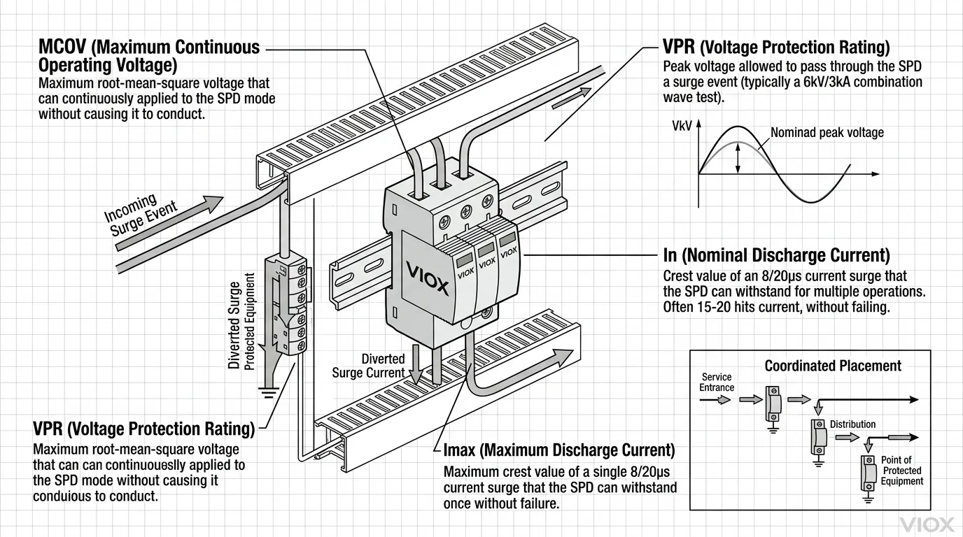
    Surge Protection Devices are electrical safety components designed to protect your home’s electrical systems from voltage spikes. A surge protector shields electrical appliances from voltage spikes by blocking or shorting any excess voltage. When it comes to EV chargers, SPDs act as a critical line of defense against potentially damaging electrical events.

    Think of an SPD as an electrical pressure relief valve. When a power surge occurs—whether from lightning, grid switching, or equipment failures—the device detects the excess voltage and safely diverts it to ground, preventing it from reaching your expensive EV charging equipment.

    Why EV Chargers Are Vulnerable to Power Surges

    EV Chargers

    Modern EV chargers contain sophisticated electronic components that manage the complex process of safely charging your vehicle’s battery. EV chargers rely on advanced circuitry to safely and efficiently charge your electric car’s battery, and a power surge can overload and permanently damage those components.

    Several factors make EV chargers particularly susceptible to surge damage:

    • Sensitive Electronics: Today’s smart chargers include WiFi connectivity, smartphone apps, load balancing features, and safety monitoring systems—all vulnerable to electrical spikes.
    • Outdoor Exposure: EV chargers are typically installed outside, making them more susceptible to lightning strikes and weather-related electrical disturbances.
    • High Power Circuits: Level 2 chargers operate on 240V circuits with 30-50 amp capacity, making them prime targets for surge events that can cause significant damage.
    • Continuous Connection: Unlike other appliances, EV chargers remain connected to your electrical system 24/7, creating constant exposure to potential surge events.

    Legal Requirements: What the Regulations Say

    UK Regulations (18th Edition Amendment 2)

    The new 18th Edition Amendment 2 of the Wiring Regulations came into effect on September 27, 2022, stating that all new electrical circuits must have Surge Protection Devices (SPDs) fitted. Since EV charger installations require new dedicated circuits, this regulation directly applies to residential EV charging installations.

    However, the regulations include an important provision: customers can opt out of having a Surge Protection Device at the time of their EV charger installation if they wish to do so, meaning the overall decision is down to you as the customer.

    Key UK Requirements:

    • SPDs required for all new electrical circuits
    • EV charger installations fall under this requirement
    • Customer opt-out allowed with proper documentation
    • Professional installation by qualified electricians mandatory

    US Regulations (NEC 2020/2023)

    The United States follows the National Electrical Code, which has evolved to require surge protection in residential applications. NEC 2023 Section 230.67(A) requires that all services supplying dwelling units shall be provided with a surge-protective device (SPD).

    NEC Requirements Include:

    • Type 1 or Type 2 SPD required for dwelling units
    • Protection must be integral to service equipment or located immediately adjacent
    • Requirements expanded in 2023 to include multifamily dwelling units, dormitory units, guest rooms and guest suites

    State Adoption Varies: As of February 2023, the 2020 NEC is in effect in twenty-five states, while other states use older versions. Check with your local authority having jurisdiction for specific requirements in your area.

    International Standards and Best Practices

    While regulations vary globally, the trend toward mandatory surge protection reflects growing recognition of electrical safety importance in our increasingly electronic world. Countries like Australia, Canada, and Germany have similar requirements developing for residential electrical installations.

    Types of Surge Protection for EV Chargers

    Type 1 SPDs (Service Entrance Protection)

    Type 1 SPDs are installed before the main device in the load center and provide the first line of defense against external surges from the utility grid. These devices typically mount at your electrical meter or main service panel.

    Best for:

    • Homes with overhead power lines
    • Areas with frequent lightning activity
    • Properties with existing lightning protection systems

    Type 2 SPDs (Load Center Protection)

    Type 2 SPDs are positioned on the load side of the main disconnect and are the most common choice for residential EV charger protection. These surge protection devices are normally fitted in the home fuse box, or consumer unit, at the same time as the charger is installed.

    Advantages:

    • Protects against both external and internal surges
    • Easier installation during EV charger setup
    • Covers the entire home electrical system
    • Most cost-effective for residential applications

    Type 3 SPDs (Point-of-Use Protection)

    Type 3 devices provide protection at individual outlets or equipment. Type 3 plug-in surge protectors do not provide adequate protection on their own for EV chargers but can serve as supplementary protection.

    Whole House vs. Dedicated EV Circuit Protection

    Per the NEC 2020, a UL1449 Listed SPD must be installed at the incoming 120/240Vac main service panel, providing what is referred to as a “Whole House Surge Protector”. This approach protects your EV charger while simultaneously safeguarding all other electrical devices in your home.

    The Real Costs: Investment vs. Risk

    SPD Installation Costs

    UK Pricing:

    • SPD devices: £30-£160 typical range
    • Professional installation typically included in EV charger setup
    • Small additional cost when installed during EV charger installation

    US Pricing:

    • Decent whole house surge protector: $300 for device, $200 for installation
    • Realistic total cost: $500 on the high end
    • Some installations as low as $250 including parts

    Cost of EV Charger Damage

    Without surge protection, electrical damage can be catastrophic and expensive:

    • EV Charger Replacement: $800-$2,500+ for quality Level 2 chargers
    • Vehicle Electronics: Modern EVs contain thousands of dollars in sensitive electronics
    • Home Electrical Damage: Surges can damage multiple appliances and require extensive rewiring

    If damage occurs from an electrical surge, the cost to replace or repair the damaged charging equipment is significantly higher than the small cost of an SPD.

    Insurance and Warranty Implications

    Critical Consideration: It is important to read the small print of manufacturers’ product warranties, and home insurance policies, that may not be valid if such a protective device is not installed.

    Many EV charger manufacturers and insurance companies may deny claims for surge-related damage if proper protection wasn’t installed. Payments or replacement products may not be issued if a claim must be made, so it is well worth understanding the significance of electrical surge protection when it comes to insurance cover and warranty claims.

    Benefits Beyond Compliance

    Protecting Your Investment

    Equipment Longevity: SPDs extend equipment life by knocking down both large and small electrical surges that can gradually degrade electronic components over time.

    Vehicle Protection: Modern EVs are essentially computers on wheels. A surge that enters through the charging cable can potentially damage your vehicle’s battery management system, onboard computer, or other expensive electronic components.

    System Reliability: Proper surge protection ensures consistent, safe charging performance and reduces the likelihood of unexpected charger failures.

    Peace of Mind

    Weather Protection: Lightning strikes, faulty electrical equipment or wiring, and restoration of power after an outage are all common culprits for power surges. SPDs provide protection against all these scenarios.

    24/7 Protection: Even when you’re not actively charging, your EV charger remains connected to your electrical system. Surge protection provides round-the-clock safety monitoring.

    Future-Proofing: As home electrical systems become increasingly sophisticated with smart home technology, whole-house surge protection becomes even more valuable.

    Common Causes of Power Surges Affecting EV Chargers

    Ev chargers (1)

    Lightning Strikes

    Lightning strikes are among the most common causes of electrical power surges. Even indirect strikes on nearby power lines can send damaging voltage spikes through the electrical grid to your home.

    Risk Factors:

    • Geographic location (Florida, Texas, Colorado have highest lightning activity)
    • Overhead vs. underground power lines
    • Proximity to tall structures or open areas

    Grid-Related Surges

    Power Restoration: When electricity is restored after outages, the sudden influx of power can create voltage spikes.

    Equipment Switching: Utility companies regularly switch large electrical equipment on and off, potentially creating surges that travel through power lines.

    Grid Instability: Aging electrical infrastructure and increasing demand can create voltage fluctuations that stress connected equipment.

    Internal Electrical Issues

    Large Appliance Cycling: When high-power appliances like air conditioners or electric water heaters turn on and off, they can create internal surges within your home’s electrical system.

    Faulty Wiring: Deteriorating electrical connections or damaged wiring can create dangerous voltage spikes that surge protection helps contain.

    Installation Considerations

    Professional Installation Requirements

    Qualified Electricians Only: It is imperative that EV chargers are installed by qualified electricians who have specific training in EV charge point installation. The same applies to surge protection devices.

    Certification Requirements: Look for electricians certified in EV charger installation who understand current electrical codes and surge protection requirements.

    Safety First: Dealing with electricity carries inherent risks, underscoring the necessity for professional installation.

    Optimal Placement Strategies

    Main Panel Installation: Most residential SPDs install at the main electrical panel, providing comprehensive protection for the entire home including the EV charger circuit.

    Proper Grounding: The SPD ground connection should use a dedicated conductor to established building/service ground for optimal performance.

    Wire Run Considerations: Shorter wire runs between the SPD and supply conductors provide better surge response.

    Choosing the Right SPD

    Joule Rating: For EV chargers, a minimum rating of 2000 joules is recommended to handle the energy from significant surge events.

    Clamping Voltage: Look for a clamping voltage of around 400V for optimal protection specific to EV charging applications.

    Response Time: A good surge protector should react in less than a nanosecond to provide effective protection.

    Making the Decision: Do You Need SPD for Your EV Charger?

    Risk Assessment Factors

    Geographic Lightning Risk: Areas with frequent thunderstorms benefit most from surge protection. Check local lightning strike frequency data.

    Power Grid Reliability: Regions with aging electrical infrastructure or frequent outages have higher surge risk.

    Investment Protection: Consider the combined value of your EV charger ($800-2,500) and vehicle electronics (potentially thousands) when weighing protection costs.

    When You Can Opt Out (And Why You Shouldn’t)

    While regulations allow opting out, most reliable advice leans heavily towards including surge protection during the installation of EV chargers. The minimal cost compared to potential damage makes surge protection a wise investment.

    Opt-Out Documentation: If you decide to proceed without having a surge protection device fitted during the installation, you may be asked to sign a document that acknowledges that you have been informed of the potential risks.

    Professional Recommendations

    If qualified electricians recommend installing a surge protection device, it is certainly worth acting on their advice. These professionals understand local electrical conditions and code requirements better than anyone.

    Installation Process and Maintenance

    What to Expect During Installation

    Timeline: SPD installation typically adds 30-60 minutes to an EV charger installation appointment.

    Minimal Disruption: Installation usually requires brief power interruption while connections are made at the main panel.

    Testing: Professional installers will test the SPD to ensure proper operation before completing the job.

    Ongoing Maintenance Needs

    Monitoring: Most modern SPDs include indicator lights showing operational status.

    Replacement Indicators: SPDs can wear out after protecting against surges and may need replacement every 5-10 years.

    Professional Inspection: Include SPD status in regular electrical system inspections.

    Frequently Asked Questions

    Does my EV charger have built-in surge protection?

    EV chargers do not have a built-in SPD – the SPD is an external device installed by your electrician, usually at the consumer unit. While some chargers include basic electrical protection features, they don’t provide comprehensive surge protection.

    Can I install surge protection myself?

    No. SPD installation requires working with your main electrical panel and should only be performed by qualified, licensed electricians. Improper installation can create safety hazards and void warranties.

    Will surge protection affect my EV charging speed?

    No. Properly installed SPDs don’t affect normal electrical operation or charging speeds. They only activate during surge events to protect your equipment.

    What happens if I opt out of surge protection?

    You assume full financial responsibility for any surge-related damage to your EV charger, vehicle, or home electrical system. Insurance and warranty claims may also be denied.

    How often do surge protection devices need replacement?

    SPDs typically last 5-10 years but may need replacement sooner if they’ve protected against multiple surge events. Modern devices include status indicators to show when replacement is needed.

    Conclusion: Protecting Your EV Investment

    The question isn’t really whether EV chargers need surge protection—electrical codes increasingly require it for good reason. The real question is whether you’re willing to accept the significant financial and safety risks of opting out.

    Key Decision Factors:

    • Cost-Benefit Analysis: $150-$500 protection vs. $2,000+ potential damage
    • Regulatory Compliance: Required by modern electrical codes with opt-out provisions
    • Insurance/Warranty Protection: May be required for coverage validity
    • Peace of Mind: Protection against unpredictable electrical events

    Our Recommendation: Install surge protection during your EV charger installation. SPDs represent a smart investment, safeguarding your home, your assets and ensuring compliance with safety regulations.

    The minimal additional cost provides comprehensive protection for one of your most expensive home electrical installations while ensuring compliance with current safety standards. When qualified electricians recommend surge protection, it’s wise to listen.

    Ready to Install Your EV Charger Safely?

    Contact qualified, certified electricians in your area who understand both EV charger installation and current surge protection requirements. Get multiple quotes that include surge protection to ensure you’re getting the best value for comprehensive electrical safety.

    Protect your investment. Protect your home. Charge with confidence.

    Related

    What is a Surge Protection Device (SPD)

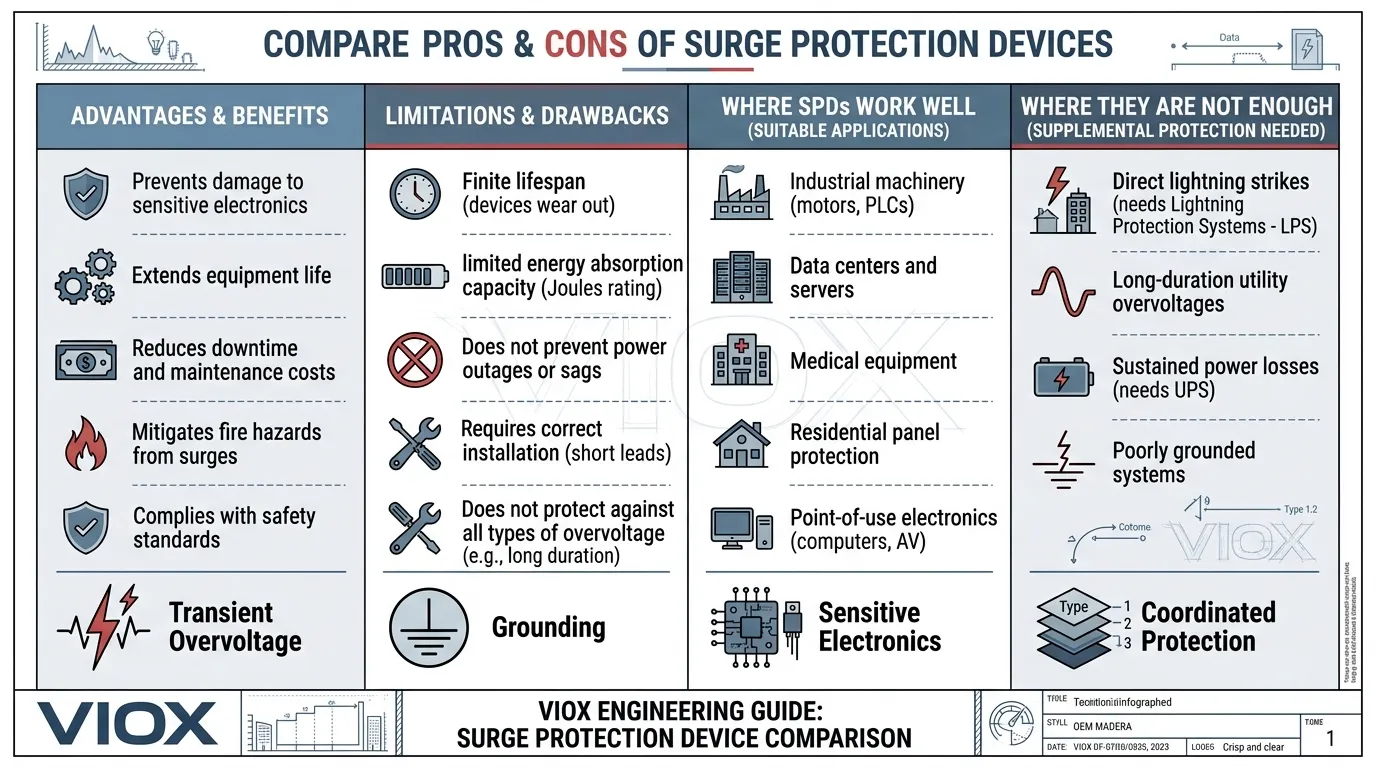
    Surge Protection Devices: Pros and Cons

    Surge Protection Devices vs Surge Arresters

    Surge Protective Device Type 1 vs Type 2 vs Type 3

  • Where Is the Distribution Box Located and How to Find It

    Where Is the Distribution Box Located and How to Find It

    Bottom Line Up Front: Your home’s distribution box (electrical panel) is typically located in the basement, garage, utility room, or mounted outside near your electrical meter. To find it quickly, look for a rectangular gray metal box about the size of a medicine cabinet, often positioned close to where power lines enter your home.

    When your power goes out or a circuit breaker trips, knowing exactly where your distribution box is located can save you time, money, and frustration. Whether you call it an electrical panel, breaker box, or circuit breaker panel, this crucial component controls all the electricity in your home—and every homeowner should know how to locate it.

    What Is a Distribution Box and Why You Need to Find It

    ATS in Panel

    A distribution box, commonly known as an electrical panel or breaker box, serves as the central control hub for your home’s electrical system. The main service panel is typically located in a home’s basement or utility room, though locations can vary significantly based on home design and local building codes.

    An electrical panel controls the flow of electricity to specific circuits around the house, and includes a protective fuse or circuit breaker for each circuit. Think of it as the command center that safely distributes power throughout your home while protecting against electrical overloads and short circuits.

    Common Reasons to Locate Your Distribution Box

    Understanding when and why you need to access your electrical panel helps highlight its importance:

    Power Restoration: The main reason you need to locate your panel is to turn power back on to a circuit. If a fuse has blown due to an overloaded outlet in your home, you’ll need to locate the panel in order to replace the fuse and restore power.

    Emergency Situations: During floods, fires, or electrical emergencies, you need immediate access to shut off power to your entire home using the main breaker.

    Home Maintenance: Any electrical work in your home requires turning off power to specific circuits, which you control through the distribution box.

    Circuit Troubleshooting: When outlets stop working or lights go out in specific areas, you’ll need to identify and reset tripped breakers.

    Where Is the Distribution Box Located? Common Placement Areas

    Indoor Locations

     indoor electrical panel

    Basements and Utility Rooms
    The main service panel is typically located in a home’s basement or utility room. These areas provide easy access while keeping the panel out of sight during daily activities.

    Garages:
    If you live in a house, then typically your electrical panel will be located outside of the house or in the garage. Garages offer convenient access and sufficient space for electrical work.

    Kitchen and Pantry Areas:
    The electric service panel may be tucked away in a built-in pantry adjacent to the kitchen or a utility closet. Some panels are strategically placed behind appliances or in kitchen utility areas.

    Closets and Hallways:
    For reasons of aesthetics and security, domestic circuit breaker panels and consumer units are normally located in out-of-the-way closets, attics, garages, or basements. However, building codes prohibit installation in clothing closets.

    Outdoor Locations

    outdoor distribution box

    Exterior Walls Near Electrical Meter:
    Breaker boxes are commonly found near the electric meter, often on an exterior wall facing the street or in a designated utility area on your property. This placement allows easy utility access and emergency shutoff.

    Side or Rear of House:
    Depending on the layout and local regulations, they may also be located on the side or rear of the house. The specific location often depends on transformer placement and utility company requirements.

    How to Find Your Distribution Box: Step-by-Step Guide

    Step 1: Know What You’re Looking For

    The panel itself is a rectangular looking metal box, usually mounted into the walls of your home. This rectangle should have a cover on it so that it looks like a flat piece of wall or a metal box.

    Visual Characteristics:

    • Rectangular gray or black metal box
    • Approximately 14-20 inches wide, 20-40 inches tall
    • Hinged door or removable cover
    • Usually mounted flush against a wall
    • May have warning labels or utility company markings

    Step 2: Start with the Electrical Meter

    When I have needed to find electrical panels in the past, starting outside, near the place that the city powerline connects to the house has always been a good place to begin the search.

    Follow These Clues:

    1. Locate your electrical meter (usually outside)
    2. Your main electrical panel is typically near your electric meter, which is how your utility measures how much electricity you use
    3. One way to find the panel is to go outside and locate the service drop and service head on your roof. The service panel should be directly below
    4. Check the nearest interior wall to the meter location

    Step 3: Search Common Indoor Areas

    Systematic Indoor Search:

    1. Basement: Check walls near the foundation, especially areas closest to the electrical meter
    2. Garage: Look along interior and exterior walls, particularly near the garage door or utility areas
    3. Utility Room: Search near water heaters, furnaces, or laundry equipment
    4. Kitchen: Check pantries, utility closets, or areas behind appliances
    5. Hallways: Look for recessed panels in hallway walls

    Step 4: Check for Multiple Panels

    Sometimes, there’s also a “sub-panel” that controls various circuits in a different area. Make sure you identify the main electrical panel, which controls power to your entire home.

    Distinguishing Main from Sub-Panels:

    • Main panels are typically larger and closer to the electrical meter
    • If your home has multiple electrical panels, the main electrical panel is typically the one that’s closest to your electrical meter
    • The main panel contains the main breaker that can shut off power to the entire house

    Safety Tips for Locating and Accessing Your Distribution Box

    Safety Precautions

    Locate your electrical panel when it’s light outside or when the lights are on. If you’ve never located your panel and the power goes out in the night, you will be hunting and fumbling with a flashlight.

    Essential Safety Guidelines:

    • Never touch electrical panels with wet hands
    • Ensure adequate lighting when working with the panel
    • Keep the area around the panel clear of stored items
    • If your electrical panel does not have a cover be sure to contact an electrician to have them inspect and install a cover, especially because an uncovered panel can prove to be extremely dangerous

    Understanding Panel Components

    Once you locate your distribution box, you’ll see several key components:

    Circuit Breakers: These are called circuit breakers, which will be in the center of the panel itself and there can be as many as 50+ or as few as 10. These circuit breakers are the “regulators” of power in your home and trip if there is an electrical problem in any part of your home.

    Main Breaker: The largest switch, usually at the top or bottom, controls power to the entire home.

    Labels: Next to the breakers there may be writing or a place for writing, this is to help identify which breakers control power in the different parts of your home or apartment.

    Code Requirements and Proper Distribution Box Placement

    National Electric Code (NEC) Requirements

    NEC 110.26 states that the electrical panel and equipment must be placed in a location with proper clearance around them. There should be at least a 3 feet clearance in front of the electrical panels.

    Clearance Requirements:

    • Front clearance: Minimum 3 feet of clear space
    • Side clearance: At least 30 inches on both sides
    • Height requirements: The electrical box height should be 4-feet tall (off the ground) at a minimum—with an average height of 5–6 feet
    • Door operation: Panel door must open at least 90 degrees

    Prohibited Locations

    Areas Where Panels Cannot Be Installed:

    • Bathrooms or similar wet locations
    • Clothing closets
    • Areas with insufficient working space
    • Locations that can be blocked by stored items

    Troubleshooting: When You Can’t Find Your Distribution Box

    Check Apartment-Specific Locations

    If you live in an apartment the location of your electrical panel also could vary, but is most likely in side the apartment, usually in the kitchen or bathroom areas.

    Look for Hidden or Disguised Panels

    Some distribution boxes may be:

    • Painted to match wall colors
    • Located behind removable panels
    • Positioned in unexpected utility areas
    • Concealed in built-in cabinetry (though this violates code)

    When to Call a Professional

    If you cannot locate your distribution box after thorough searching, contact a licensed electrician. They can help identify your electrical panel location and ensure it meets current safety codes.

    Maintaining Access to Your Distribution Box

    Keep the Area Clear

    Make sure the area around your electrical panel is clutter-free. There must be 3 feet of clearance in front of your electrical panels, and the door must be able to open at least 90 degrees.

    Ensure Family Awareness

    Make sure everyone in the home knows the location of your electrical box. You can perform a mock fire drill with your family so everyone knows the ins and outs of your electrical panel.

    Label Everything Clearly

    Take time to properly label each circuit breaker so family members can quickly identify which breaker controls specific areas or appliances during emergencies.

    Conclusion: Taking Control of Your Home’s Electrical System

    Knowing where your distribution box is located and how to access it safely puts you in control of your home’s electrical system. Whether you need to reset a tripped breaker, shut off power for maintenance, or respond to an emergency, quick access to your electrical panel can prevent minor issues from becoming major problems.

    Key Takeaways:

    • Most distribution boxes are located in basements, garages, utility rooms, or outside near the electrical meter
    • Always prioritize safety when locating and accessing electrical panels
    • Maintain proper clearance and ensure family members know the panel location
    • Contact professionals when you need help locating or working with electrical systems

    By following this guide, you’ll never have to wonder “where is the distribution box located” again. Take a few minutes today to locate your electrical panel, test your knowledge of its components, and ensure your family is prepared for any electrical situation that may arise.

    Frequently Asked Questions About Distribution Box Locations

    Can an electrical panel be located in a bedroom?

    According to the NEC, electric panels are allowed inside bedrooms, but it’s advised homeowners to place beds a reasonable distance from the breaker box itself. While not prohibited by code, many homeowners prefer to move panels out of bedrooms for aesthetic and safety reasons.

    Is it safe to have an electrical panel in a closet?

    NEC 240.24(D) states that overcurrent devices shall not be located in the vicinity of easily ignitable material, such as in clothes closets. However, utility or storage closets that don’t contain flammable materials may be acceptable if they meet clearance requirements.

    Can electrical panels be installed in bathrooms?

    NEC 240.24(E) states that in dwelling units, dormitories, and guest rooms or guest suites, overcurrent devices shall not be located in bathrooms. This is strictly prohibited for safety reasons due to moisture and potential water exposure.

    What are the minimum clearance requirements around an electrical panel?

    NEC 110.26 states that the electrical panel and equipment must be placed in a location with proper clearance around them. There should be at least a 3 feet clearance in front of the electrical panels. Additional requirements include:

    • Minimum 30 inches of lateral clearance
    • Panel door must open at least 90 degrees
    • Adequate headroom (6.5 feet minimum)

    How much does it cost to move an electrical panel?

    The cost to move an electrical panel is around $1,500 to $2,000 on average. This significant expense is due to the complex wiring modifications required and the need for permits and professional installation.

    Can electrical panels be installed outside?

    Yes, electrical panels can be installed outdoors, but they require weatherproof enclosures and proper protection against the elements. Breaker boxes are commonly found near the electric meter, often on an exterior wall facing the street or in a designated utility area on your property.

    What is the required height for electrical panel installation?

    The height should not be higher than 6’7″ or lower than 4′, while there is a 12″ clearance from either side of the meter. This ensures the panel is accessible to adults while remaining safe from children.

    What if I can’t find my electrical panel in my apartment?

    If you live in an apartment the location of your electrical panel also could vary, but is most likely inside the apartment, usually in the kitchen or bathroom areas. Check utility closets, hallway areas, or contact your building management for assistance.

    Are there any other prohibited locations for electrical panels?

    A panel cannot be located: 1) Where exposed to physical damage, 2) In the vicinity of easily ignitable material, 3) In bathrooms, 4) Over steps. Additionally, panels cannot be installed in fire-rated walls or areas that don’t meet clearance requirements.

    Can I install an electrical panel in my laundry room?

    Unlike clothes closets, there is no specific language in the NEC saying you cannot put an electrical panel in a storage room, including laundry rooms. However, you must ensure adequate clearance around washers and dryers and that the area meets all safety requirements.

    Do I need a permit to move my electrical panel?

    Because extending or shortening wires throughout the home is a significant undertaking, you’ll likely need a permit from your local municipality. You’ll also need to contact the electric company to ensure the move is safe.

    Why should I know where my electrical panel is located?

    Make sure everyone in the home knows the location of your electrical box. You can perform a mock fire drill with your family so everyone knows the ins and outs of your electrical panel. This knowledge is crucial for emergency situations, power outages, and routine maintenance.

    Related

    Distribution Box and Selection Guide

    Understanding the Difference: Electrical Distribution Box vs. Power Distribution Box

    AC Distribution Box vs. DC Distribution Box: A Comprehensive Guide

    Distribution Boxes vs. Combiner Boxes: Key Differences and Uses in Electrical Systems

  • How to Select the Right RCBO

    How to Select the Right RCBO

    To select the right RCBO, start with the circuit—not the catalog. Establish the load current, corrected conductor capacity, possible residual-current waveform, required residual sensitivity, inrush current, monitored conductors, maximum prospective short-circuit current, supply characteristics, and required product approval. Then specify the RCBO in this order:

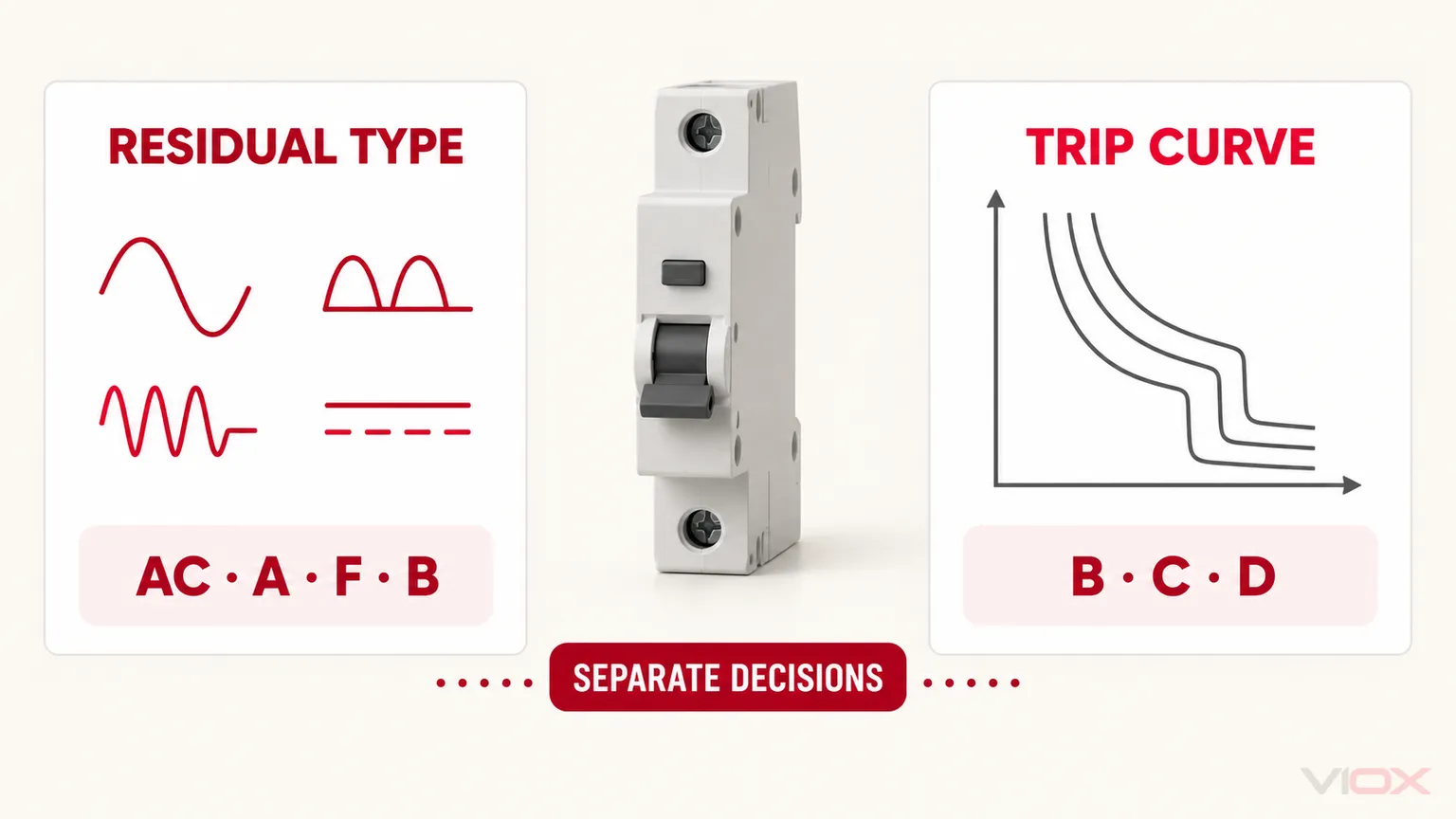
    1. Residual-current type: AC, A, F, or B
    2. Residual sensitivity, IΔn: such as 10 mA, 30 mA, 100 mA, or 300 mA where permitted and required
    3. Rated current, In: coordinated with design current and conductor capacity
    4. Overcurrent curve: normally B, C, or D for relevant IEC-style products
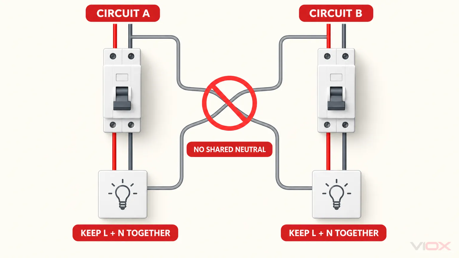
    5. Poles and neutral arrangement: matching every conductor that must be monitored and disconnected
    6. Short-circuit capacity: not less than the maximum prospective short-circuit current under the applicable declaration or an exact documented combination
    7. Product conditions: voltage, frequency, standard, supply dependence, line/load direction, terminals, busbar compatibility, and market approval

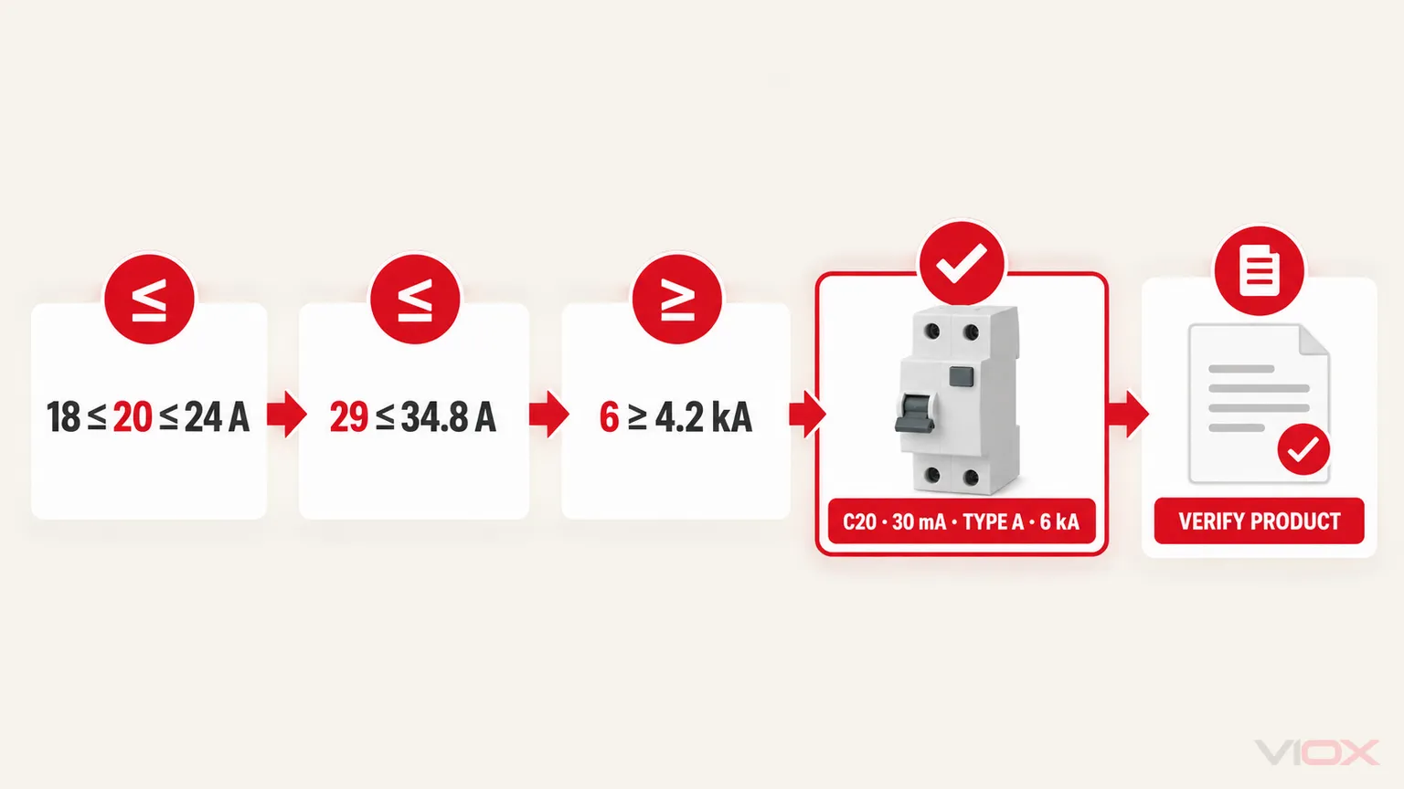
    Do not approve a model while any of these fields is unknown. A C32 30 mA Type A 6 kA RCBO is not merely a “32 A breaker”; each marking answers a separate engineering question.

    AC scope boundary: This guide primarily addresses AC RCBOs within the scope of IEC/EN 61009-1. The 2024 IEC edition covers relevant RCBOs at rated operational voltages not exceeding 440 V AC and rated frequencies of 50 Hz, 60 Hz, or 50/60 Hz, within its other stated limits. For a DC circuit, stop and verify the applicable DC protective-device standard, polarity, voltage per pole, arc-extinguishing design, disconnection arrangement, and exact manufacturer documentation. Do not transfer the AC selection result to a DC device.

    If you first need to understand the device rather than select it, begin with What Is an RCBO?. The RCBO full form guide separately owns abbreviation intent.

    RCBO Selection Input Sheet

    Collect these inputs before comparing models. “To be confirmed” is a valid design status; guessing a rating is not.

    Input What to record Why it changes the RCBO choice
    Supply For this guide: AC voltage, frequency, phases, neutral, and earthing context; flag any DC circuit for a separate standards and product review Controls product scope, poles, monitoring, polarity, and declared ratings
    Circuit duty Lighting, sockets, heater, motor, inverter, EV charger, PV, mixed load, or another defined duty Indicates leakage waveform, normal leakage, inrush, and continuity needs
    Design current, IB Maximum expected load current using the project design method Sets the lower bound for the overcurrent rating
    Conductor capacity, IZ Corrected ampacity after installation method, ambient temperature, grouping, insulation, and other derating Sets the upper bound for the protective-device rating
    Inrush or starting current Magnitude and duration from equipment data or design evidence Helps distinguish B, C, or D curve suitability
    Residual-current evidence Equipment instructions, converter topology, possible AC, pulsating DC, mixed-frequency, or smooth DC components Determines Type AC, A, F, or B suitability
    Normal leakage budget Per-load leakage, filters, long cables, SPDs, and grouped equipment Prevents an unrealistically sensitive or overloaded residual-current arrangement
    Protection purpose Additional protection, upstream residual-current protection, fault/fire-risk mitigation, or coordination where permitted Informs IΔn and time-delay or selectivity requirements
    Maximum PSCC Maximum prospective short-circuit current at the exact installation point Sets the minimum applicable breaking capacity
    Disconnection arrangement Conductors to be monitored, switched, and protected Determines 1P+N, 2P, 3P, 3P+N, or 4P arrangement
    Installation system Enclosure, DIN rail, busbar, terminal conductors, ambient limits, supply direction Controls mechanical and declared installation compatibility
    Compliance Required product standard, national adoption, certification, project specification Determines whether a technically plausible device is legally and contractually acceptable

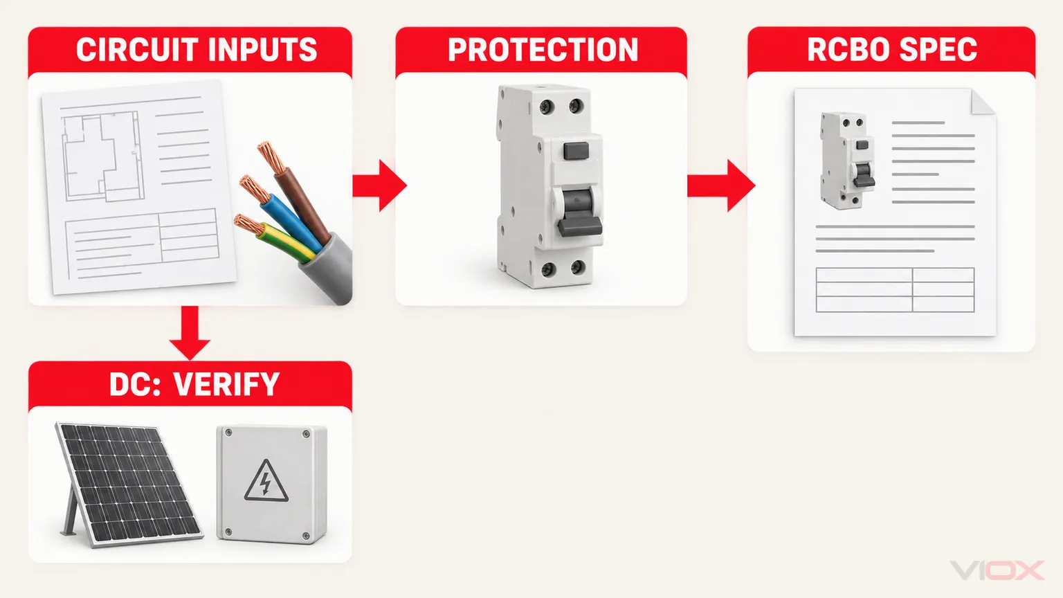
    RCBO selection workflow from verified AC circuit inputs to a complete device specification

    RCBO Rating Chart: What Each Marking Decides

    This chart prevents the most common selection error: treating unrelated markings as substitutes.

    RCBO field Typical markings or options Select it from It does not tell you
    Residual-current type AC, A, F, B Possible residual-current waveform and equipment instructions Overcurrent inrush tolerance
    Residual sensitivity IΔn, for example 30 mA Protection purpose, local rules, leakage budget, and selectivity design Continuous load rating
    Rated current In, for example 16 A, 20 A, 32 A IB, corrected IZ, and installation conditions Short-circuit breaking capacity
    Trip curve B, C, D Inrush, fault current, loop conditions, and disconnection requirements Residual-current Type B capability
    Poles 1P+N, 2P, 3P, 3P+N, 4P Supply and required monitored/disconnected conductors Exact terminal arrangement
    Breaking capacity 6 kA, 10 kA, 16 kA, or another declared value Maximum PSCC, standard, voltage, and exact backup evidence Rated current or residual sensitivity
    Voltage and frequency Ue, 50/60 Hz, other declared values Actual supply Market acceptance
    Standard and approvals IEC/EN 61009-1, IEC 62423 where applicable, national marks Destination market and project specification Suitability for every installation environment
    Direction and supply dependence Bidirectional/unidirectional; functionally dependent/independent of line voltage Exact product documentation and system design A universal wiring arrangement

    RCBO selection separates residual-current type from the overcurrent trip curve

    Step 1: Select the Residual-Current Type

    The residual-current type describes which residual-current waveforms the device is designed to detect. It is independent of the B, C, or D overcurrent curve.

    Type Detection boundary in practical terms Selection direction
    Type AC Sinusoidal AC residual current Consider only where the connected equipment and local rules allow it
    Type A Sinusoidal AC plus pulsating DC residual current Common starting point for many modern single-phase electronic loads, but not universal
    Type F Type A behavior plus defined composite-frequency behavior for relevant single-phase equipment Consider when equipment or design evidence identifies inverter-related residual currents within its scope
    Type B Broader response including smooth DC residual current under its declared conditions Consider when equipment can produce smooth DC or other residual currents that require Type B behavior

    The load category alone is insufficient. An EV charger, PV inverter, heat pump, or variable-speed drive can incorporate residual-current monitoring that changes the external protection requirement. Conversely, the words “domestic appliance” do not prove Type AC is acceptable. Verify the equipment manufacturer’s instructions, converter topology, local wiring rules, and coordination with upstream devices.

    IEC 62423 defines additional requirements for Type F and Type B residual-current devices used with the relevant general RCD standards. For the full waveform comparison and the important difference between Type B RCBO and B-curve RCBO, use the dedicated RCBO Type AC vs A vs F vs B guide.

    Stop condition: do not choose the residual-current type when the equipment’s leakage-current behavior or protection instructions are unavailable.

    Step 2: Select Residual Sensitivity (IΔn)

    IΔn is the rated residual operating current. It is not the RCBO’s ampere rating and it should not be selected from a “lower is always safer” rule.

    IΔn value Common design role What must be checked
    10 mA High-sensitivity protection for defined special applications Local requirement, individual circuit use, and normal leakage margin
    30 mA Additional protection on many final circuits in IEC-derived installations Circuit scope, local rules, accumulated leakage, and required disconnection behavior
    100 mA Upstream residual-current protection, fault/fire-risk mitigation, or coordination where permitted Whether downstream additional protection remains required and whether selectivity is documented
    300 mA Upstream or fire-risk strategy where specified Earthing system, local rules, downstream coordination, and time delay where required

    These are roles, not universal prescriptions. Estimate or obtain the circuit’s normal standing leakage, including connected equipment, EMC filters, long cable runs, surge protective devices, and future loads. An RCBO can trip correctly yet still create poor service continuity if normal leakage sits too close to the selected operating threshold.

    Where upstream and downstream residual-current devices are used, selectivity depends on more than different mA values. Time characteristics, device type, circuit arrangement, and manufacturer or project evidence also matter.

    Stop condition: do not finalize IΔn until the protection purpose and local installation rule are known.

    Step 3: Coordinate Rated Current with the Load and Conductor

    For an IEC-style design, the basic relationship is:

    IB ≤ In ≤ IZ

    where:

    • IB is the circuit design current;
    • In is the RCBO rated current; and
    • IZ is the conductor’s corrected current-carrying capacity.

    The logic is simple: the device must carry the intended load, but it must not leave the conductor inadequately protected. The IEC 60364-4-43 scope addresses protection against overcurrent in low-voltage installations; the actual conductor calculation must follow the applicable installation standard and project conditions.

    IB ≤ In ≤ IZ is a necessary screening condition, not the whole overload-protection verification. Where the applicable installation standard requires it, also verify:

    I₂ ≤ 1.45 × IZ

    I₂ is the current that causes effective operation of the protective device within the conventional time defined by the applicable product standard or manufacturer data. Check the actual RCBO characteristic and all conductor-protection conditions required by the local installation standard, including cases where overload protection may be treated differently. The IET provides a public BS 7671 example of the complete IB, In, IZ, and I₂ conditions; use it as an accessible UK example, not as a substitute for the rules governing another market.

    Do not use fixed shortcuts such as “2.5 mm² always means 20 A.” Conductor material, insulation, installation method, grouping, ambient temperature, terminals, harmonics, voltage drop, load duty, and national rules can all change the result. The product’s reference ambient and derating information must also be considered when it is installed in a warm or densely populated board.

    Stop condition: if corrected IZ is not known, the RCBO ampere rating is not ready for approval.

    Step 4: Select the Overcurrent Curve from Inrush and Fault Behavior

    B, C, and D are overcurrent characteristics. They indicate different instantaneous magnetic trip regions for relevant IEC-style protective devices; they are not residual-current types.

    Curve Common reference range Practical selection question Main misuse risk
    B About 3–5 × In Is normal inrush low enough while required fault disconnection is achieved? Nuisance tripping on transformers, motors, or large driver groups
    C About 5–10 × In Does the circuit have moderate inrush and sufficient fault current? Assuming it is a universal “commercial” curve
    D About 10–20 × In Is high inrush documented, and can the circuit still meet fault-disconnection requirements? Using it to mask startup trips where fault current is too low

    Use the equipment’s starting-current data and duration, then check the manufacturer’s time-current curve and the project’s fault or loop conditions. A higher-inrush curve can ride through startup current, but it also needs a higher current to enter its instantaneous region.

    For graph reading, thermal behavior, magnetic bands, and coordination limits, use the circuit-breaker trip-curve guide.

    Stop condition: do not move from B to C or D only because an existing device trips. First determine whether the event is overload, short circuit, residual current, incorrect wiring, normal leakage accumulation, or genuine inrush.

    Step 5: Select Poles and the Neutral Arrangement

    Every conductor that must be included in the residual-current measurement must pass through the device’s intended sensing path. The required disconnection arrangement depends on the supply, earthing system, local rules, and circuit function.

    Configuration Typical system context Required verification
    1P+N Single-phase final circuit Which pole has overcurrent protection, whether neutral is switched or solid, terminal layout, and permitted supply direction
    2P Single-phase circuit requiring two-pole disconnection Whether both poles are switched, which poles are protected, and how the product monitors the conductors
    3P Three-phase circuit without a neutral All three phase conductors follow the declared current path and product diagram
    3P+N / 4P Three-phase circuit with neutral Neutral monitoring and switching behavior, pole protection, and exact terminal diagram

    Marketing names are not wiring diagrams. Two products called 1P+N can differ in neutral treatment, supply dependence, terminal position, or line/load direction. Use the exact catalog number and product drawing.

    Never borrow or share a downstream neutral between separate RCBO circuits. The returned current will not match the monitored line current, which can cause tripping and unsafe commissioning assumptions. See shared neutrals and RCBO tripping for the fault logic. Use the RCBO wiring diagram guide only as a configuration reference; the selected model’s diagram remains controlling.

    Conceptual RCBO pole and neutral arrangement showing that each protected circuit keeps its monitored conductors together

    Stop condition: if neutral treatment or terminal direction is ambiguous, obtain the exact datasheet before approving the device or panel layout.

    Step 6: Verify Short-Circuit Breaking Capacity

    The applicable declared short-circuit capacity must not be less than the maximum prospective short-circuit current at the installation point:

    RCBO breaking capacity ≥ maximum PSCC at the installation point

    Read the kA figure together with the product standard, voltage, current type, and exact catalog number. A 6 kA rating can be adequate at one board and inadequate at another. A 10 kA or 16 kA label does not compensate for the wrong In, curve, IΔn, or residual-current type.

    If the standalone device rating is below the fault level, an upstream protective device may support it only through an exact manufacturer-documented backup, cascading, or conditional combination. “There is a fuse upstream” is not evidence. An assembly’s conditional short-circuit rating also does not automatically become the standalone rating of every RCBO inside it.

    Use the focused RCBO 6 kA vs 10 kA vs 16 kA selection guide to distinguish device capacity from verified combination and assembly ratings.

    Stop condition: if the maximum credible PSCC is unknown, do not finalize the RCBO kA rating.

    Step 7: Verify the Exact Product, Standard, and Installation Conditions

    IEC 61009-1 covers residual-current operated circuit-breakers with integral overcurrent protection for household and similar uses within its published scope. The current public catalog entry is IEC 61009-1:2024. A standard reference is only one field in the approval check; the destination market may require a national adoption, certification mark, or a different product framework.

    Verify the exact RCBO datasheet and nameplate for:

    • rated operational voltage and frequency;
    • rated current, residual operating current, residual-current type, and trip curve;
    • poles, protected poles, switched-neutral behavior, and terminal identification;
    • applicable short-circuit-capacity declaration and voltage;
    • function with or without line voltage, where relevant;
    • permitted line/load direction and bidirectional-use declaration;
    • temperature limits and derating;
    • conductor type, terminal capacity, tightening requirements, and busbar compatibility;
    • isolation indication and accessory compatibility where the project requires them;
    • product standard, approvals, certification, and document revision; and
    • coordination tables when the design depends on upstream backup or selectivity.

    For a deeper product-standard explanation, use the IEC 61009-1 RCBO guide.

    Stop condition: a family brochure is insufficient when the required claim is model-, voltage-, pole-, or combination-specific.

    Worked Example: From Circuit Inputs to One RCBO Specification

    This hypothetical example demonstrates the method; it is not a model recommendation or a reusable circuit schedule.

    Given Inputs

    Assume a dedicated single-phase load has the following verified design record:

    Input Example value Evidence status
    Supply 230 V AC, 50 Hz, line and neutral Inside the voltage/frequency scope being considered; market acceptance still requires verification
    Design current, IB 18 A From the project load calculation
    Corrected conductor capacity, IZ 24 A After the project’s installation and derating factors
    Candidate device rating, In 20 A Candidate for coordination check—not yet selected
    Candidate conventional operating current, I₂ 29 A From the applicable product-standard characteristic or exact manufacturer data for the hypothetical candidate
    Equipment residual-current information Pulsating DC may occur; no smooth DC or composite-frequency requirement identified From the hypothetical equipment documentation
    Project residual-current requirement 30 mA additional protection Assumed to be required by the applicable project and local installation rules
    Starting current 75 A for 20 ms From the hypothetical equipment data
    Maximum PSCC at the board 4.2 kA From the hypothetical project fault-current record
    Disconnection arrangement Single-phase circuit with line and neutral; neutral treatment to be confirmed from the exact device From the project single-line diagram plus product documentation

    1. Check Rated Current and Overload Protection

    The basic current relationship passes:

    18 A ≤ 20 A ≤ 24 A

    The additional example check also passes:

    I₂ = 29 A
    1.45 × IZ = 1.45 × 24 A = 34.8 A
    29 A ≤ 34.8 A

    This does not complete the cable design. The applicable installation standard may impose additional conductor, overload, fault-protection, voltage-drop, thermal, grouping, terminal, or disconnection requirements.

    2. Select Residual-Current Type and Sensitivity

    The hypothetical equipment record identifies pulsating DC residual current but no evidence requiring Type F or Type B behavior. Type A is therefore the candidate residual-current type. The project requirement supplies the 30 mA value. Both fields still require confirmation against the actual equipment manual, local rules, and exact RCBO documentation.

    3. Check the Trip Curve

    The starting current is 75 A ÷ 20 A = 3.75 × In for 20 ms. That ratio alone does not select the curve. Compare the complete inrush duration with the exact manufacturer time-current band and verify fault-disconnection performance. In this example, assume the documented study confirms that a C curve rides through the stated inrush and still satisfies the required fault-disconnection conditions. Without that study, the curve remains unresolved.

    4. Check Breaking Capacity

    The maximum prospective short-circuit current (PSCC) is 4.2 kA. A candidate with an applicable standalone 6 kA declaration at 230 V AC is not below that value:

    6 kA ≥ 4.2 kA

    The exact standard, voltage, model, and any assembly conditions must still match. No generic safety multiplier or undocumented upstream backup has been assumed.

    5. Produce the Bounded Output

    Subject to the stated evidence and final product verification, the example output becomes:

    Hypothetical RCBO specification: 1P+N arrangement as defined by the exact product; 230 V AC, 50 Hz; C20; 30 mA; Type A; applicable standalone short-circuit capacity of at least 4.2 kA, with a 6 kA candidate; IEC/EN 61009-1 product framework; required national approval; exact neutral treatment, supply dependence, line/load direction, terminals, temperature limits, and busbar compatibility to be confirmed from the selected catalog number.

    If the inrush study, Type A evidence, 30 mA project requirement, or exact product declaration changes, the output must be recalculated. The example is intentionally conditional so the method cannot be mistaken for a universal recommendation.

    Worked RCBO selection example converting circuit data into a conditional C20 Type A 30 mA 6 kA specification

    RCBO Selection by Application: Starting Points, Not Answers

    The following table helps identify evidence to collect. It is not a model schedule.

    Application Common starting direction Evidence that controls the final choice
    LED lighting group Often Type A; B or C curve depending on driver inrush Driver leakage and inrush data, quantity, conductor design, fault conditions, and local rules
    General socket circuit Often Type A and 30 mA in many IEC-derived designs Connected equipment, local additional-protection rules, leakage budget, IB, IZ, and PSCC
    Heater or simple resistive load Type and curve based on actual controls and inrush Electronic controls, switching arrangement, conductor design, and local requirements
    Motor, pump, or compressor Type A, F, or B depending on drive topology; curve from starting data Direct-on-line or electronic drive, leakage waveform, starting current and duration, fault level
    Heat pump or inverter air conditioner Type F or B may be required for some equipment Manufacturer instructions, converter topology, residual-current monitoring, and local rules
    EV charging The permitted route may include Type B or another documented DC-residual-current strategy EVSE design, integrated 6 mA DC detection where applicable, local rules, upstream coordination, and charger instructions
    PV inverter AC circuit Type A or B depending on inverter design and requirements Inverter topology, built-in residual-current monitoring, manufacturer instructions, and national PV rules
    Upstream distribution Higher IΔn and time selectivity may be part of the design Earthing arrangement, fire-risk strategy, downstream devices, discrimination study, and local code

    Do not copy the “common starting direction” into a bill of materials. The evidence in the final column owns the decision.

    Final RCBO Specification Template

    A selection is complete when it can be written and checked in one line plus its supporting evidence. Use this template:

    RCBO: [poles and neutral arrangement], [rated voltage/frequency], In [A], [B/C/D or other declared curve], IΔn [mA], residual-current Type [AC/A/F/B], short-circuit capacity [kA] under [standard and voltage], [direction/supply-dependence requirement], [national approval], installed in [board/busbar/terminal system], with [exact backup/selectivity document if used].

    Attach or reference:

    • load schedule and IB calculation;
    • corrected conductor capacity IZ;
    • equipment leakage-waveform and inrush evidence;
    • normal leakage budget where relevant;
    • maximum PSCC source and date;
    • exact product datasheet and wiring diagram;
    • local code or project requirement; and
    • manufacturer coordination table when the design depends on a combination.

    If those records do not support every field, the selection is incomplete. If the panel architecture itself is still undecided, compare individual RCBOs with an RCCB plus MCB arrangement before preparing the schedule.

    Selection Review Checklist

    Primary Technical Sources

    Once the circuit data and required fields are complete, compare them with the documented VIOX RCBO range. Request the exact model datasheet, certification, terminal diagram, and any required backup or selectivity table rather than selecting from a family name alone.

  • Voltage vs Current: Difference Between Volts, Amps, Watts, and Potential Difference

    Voltage vs Current: Difference Between Volts, Amps, Watts, and Potential Difference

    What Is the Difference Between Voltage and Current?

    Voltage is electrical potential difference, measured in volts (V). Current is the flow of electric charge, measured in amperes (A). Voltage pushes current through a circuit, while current describes how much charge is flowing. They are related by Ohm’s law: I = V / R.

    The simplest way to remember the difference is:

    • Voltage is the push.
    • Current is the flow.
    • Resistance limits the flow.
    • Power is the rate of electrical energy being used.

    This distinction matters in real electrical work. A circuit may have voltage present but almost no current flowing if the circuit is open. A circuit may also draw too much current if the load resistance is too low, which can overheat wires, trip a breaker, or damage equipment.


    Voltage vs Current at a Glance

    Term Symbol Unit What It Means Simple Role
    Voltage V Volt (V) Electrical potential difference between two points Pushes current
    Current I Ampere (A) Flow rate of electric charge Shows how much charge is moving
    Resistance R Ohm (Ω) Opposition to current flow Limits current
    Power P Watt (W) Rate of electrical energy use Shows work or heat produced
    Voltage and current comparison showing voltage as potential difference and current as charge flow
    Voltage vs current: voltage is the potential difference that pushes charge, while current is the actual flow of electric charge through the circuit.

    In practical terms, voltage and current must be considered together. A 230 V circuit and a 24 V control circuit behave very differently, but both can be unsafe if the available current, installation condition, and protection device are not suitable.


    What Is Voltage?

    Voltage is the electrical potential difference between two points in a circuit. It is measured in volts (V).

    If you think of electricity like water flow, voltage is similar to pressure. Higher pressure can push more water through a pipe. Higher voltage can push more current through a circuit, if the circuit path allows it.

    Examples:

    • A battery has voltage between its positive and negative terminals.
    • A wall outlet has voltage between live and neutral.
    • A power supply has output voltage between its terminals.
    • A voltage drop appears across a resistor, cable, terminal, or load when current flows.

    Voltage is always measured between two points, not “through” one point.


    What Is Current?

    Current is the flow of electric charge through a conductor or load. It is measured in amperes (A), often shortened to amps.

    Current flows only when there is a complete circuit and a driving voltage. If a switch is open, voltage may still be present on one side of the switch, but current does not flow through the load.

    Examples:

    • A lamp draws current when it is switched on.
    • A motor draws current while running.
    • A heater draws current and converts electrical energy into heat.
    • A fault can cause excessive current, which should be interrupted by a fuse, MCB, MCCB, or other protective device.

    For circuit protection, current is usually the key value. Overload and short-circuit protection devices are selected according to current, cable capacity, fault level, and application. For a deeper protection example, see VIOX’s guide to miniature circuit breakers.


    What Is Potential Difference?

    Potential difference is another way to describe voltage. It means the difference in electric potential energy per unit charge between two points.

    In everyday electrical work:

    Potential difference = voltage.

    For example, if a power supply provides 24 V DC, that means there is a 24-volt potential difference between its positive and negative terminals. If a home outlet is rated at 230 V AC, that means there is a nominal 230-volt potential difference between live and neutral.

    Potential difference is important because current does not flow just because one point has “electricity.” Current flows when there is a closed path and a voltage difference that drives charge through that path.


    Is Current Measured in Volts?

    No. Current is measured in amperes (A), not volts.

    Volts and amps measure different things:

    Question Correct Answer
    Is voltage measured in amps? No, voltage is measured in volts
    Is current measured in volts? No, current is measured in amperes
    What measures electrical pressure? Voltage
    What measures electrical flow? Current
    What measures power use? Watts

    This is a common beginner mistake. Saying “current is 230 volts” is incorrect. The correct statement would be “the voltage is 230 V” or “the current is 10 A,” depending on what is being measured.


    How to Calculate Current

    The most common formula for calculating current is Ohm’s law:

    I = V / R

    Where:

    • I = current in amperes (A)
    • V = voltage in volts (V)
    • R = resistance in ohms (Ω)

    Example:

    V = 24 V
    R = 12 Ω
    I = V / R = 24 / 12 = 2 A

    So the current is 2 amps.

    Ohms law circuit diagram showing voltage, current, resistance, and power formulas
    Ohm’s law circuit diagram: voltage, current, resistance, and power formulas shown together for DC circuit calculations.

    You can also calculate current from power:

    I = P / V

    Where:

    • I = current in amperes (A)
    • P = power in watts (W)
    • V = voltage in volts (V)

    Example:

    P = 1000 W
    V = 230 V
    I = P / V = 1000 / 230 ≈ 4.35 A

    For AC circuits with motors, transformers, or industrial loads, real current calculation may also involve power factor, phase count, efficiency, and starting current. For deeper formulas, see VIOX’s guide to low-voltage electrical formulas for panel design and maintenance.


    Voltage, Current, Resistance, and Power Relationship

    Voltage, current, resistance, and power are connected. You should not treat them as isolated values.

    Formula Meaning
    I = V / R Current increases when voltage increases or resistance decreases
    V = I × R Voltage drop increases when current or resistance increases
    P = V × I Power increases when voltage or current increases
    P = I² × R Heat loss rises sharply as current increases

    The last formula is especially important in electrical panels. A loose terminal, oxidized contact, undersized conductor, or poor crimp can add resistance. When current flows through that resistance, heat is produced. This is one reason terminal overheating and hot spots are serious maintenance issues.

    For related field troubleshooting, see VIOX’s guide to terminal block overheating in control panels.


    Volts vs Amps vs Watts

    Volts, amps, and watts are related but not interchangeable.

    Term Unit Measures Example Question
    Voltage V Electrical pressure or potential difference What voltage is the circuit?
    Current A Flow of charge How many amps does the load draw?
    Power W Rate of energy use How many watts does the device consume?

    The basic power formula is:

    P = V × I

    For example:

    V = 120 V
    I = 10 A
    P = 120 × 10 = 1200 W
    Volts amps and watts infographic showing 120 volts times 10 amps equals 1200 watts
    Volts, amps, and watts relationship: 120 volts × 10 amps = 1200 watts of power consumption.

    So the load uses 1200 watts.

    This is why a higher-voltage system can deliver the same power with lower current. Lower current can reduce voltage drop and heating losses, but the system must still be designed according to insulation, protection, and safety requirements.

    For a related power and energy distinction, see kW vs kWh.


    How to Check Voltage with a Multimeter

    To check voltage with a multimeter, you measure across two points.

    Multimeter voltage measurement diagram showing probes across two points with correct COM and voltage inputs
    Multimeter voltage measurement: probes placed across two points with the correct COM and voltage input jacks.

    Basic process:

    1. Select the correct voltage mode: AC voltage (V~) or DC voltage (V⎓).
    2. Choose a range higher than the expected voltage if the meter is not auto-ranging.
    3. Insert the black probe into the COM jack.
    4. Insert the red probe into the voltage input jack.
    5. Place the probes across the two points being measured.
    6. Read the voltage displayed on the meter.

    Important safety notes:

    • Do not measure voltage with the meter set to current mode.
    • Do not move the red probe to the current input jack when measuring voltage.
    • Use a meter and probes rated for the circuit category and voltage.
    • For mains panels, distribution boards, or industrial equipment, testing should be performed by qualified personnel.

    Voltage measurement is different from current measurement. Voltage is measured in parallel across two points. Current is usually measured in series with a load or with a clamp meter around a conductor, depending on the circuit and instrument.


    Current vs Voltage in Circuit Protection

    Voltage and current both matter for selecting electrical components.

    Device or Component Voltage Concern Current Concern
    MCB / MCCB Must be rated for system voltage Must match load current, cable capacity, and fault level
    Fuse Must be rated for AC or DC voltage Must clear overload or short-circuit current safely
    Contactor Contact voltage rating must match circuit Rated operational current depends on load category
    Cable Insulation voltage must be suitable Conductor size must carry current safely
    SPD Continuous operating voltage must match system Discharge current rating must match surge duty
    Terminal block Voltage rating must suit spacing and insulation Current rating and conductor fit must match load

    This is why selecting a device only by current or only by voltage can be dangerous. A breaker marked for a certain current may not be suitable for a different voltage or for DC use. A switch rated for AC may not safely interrupt DC because DC arcs behave differently.


    Common Mistakes About Voltage and Current

    Mistake 1: Saying current is measured in volts

    Current is measured in amps. Voltage is measured in volts.

    Mistake 2: Thinking voltage alone tells you power

    Voltage alone does not tell you how much power a load uses. Power depends on both voltage and current.

    Mistake 3: Measuring current like voltage

    Voltage is measured across two points. Current measurement requires the correct meter mode and method. Using the wrong meter input can damage the meter or create a safety hazard.

    Mistake 4: Ignoring resistance in heating problems

    Small increases in contact resistance can cause serious heating when current is high. This is why loose terminals and poor crimps are common failure points.

    Mistake 5: Assuming AC and DC ratings are interchangeable

    They are not. AC and DC circuits have different switching and arc behavior. Always check whether a device is rated for the actual AC or DC system.


    Quick Reference

    Question Short Answer
    What is voltage? Potential difference measured in volts
    What is current? Flow of electric charge measured in amps
    Is current measured in volts? No, current is measured in amperes
    What is potential difference? Another term for voltage
    How do you calculate current? I = V / R or I = P / V
    What is power? Energy use rate measured in watts
    How do you check voltage? Use a multimeter in voltage mode across two points

    FAQ

    What is the difference between voltage and current?

    Voltage is the electrical potential difference that pushes charge through a circuit. Current is the flow of charge through the circuit. Voltage is measured in volts, while current is measured in amperes.

    What is potential difference?

    Potential difference is the voltage between two points. It describes how much electrical potential energy difference exists per unit charge.

    Is current measured in volts?

    No. Current is measured in amperes, or amps. Voltage is measured in volts.

    How do you calculate current?

    Use I = V / R when voltage and resistance are known. Use I = P / V when power and voltage are known. AC motor and industrial load calculations may also require power factor and efficiency.

    What is the difference between volts and watts?

    Volts measure electrical potential difference. Watts measure power, or the rate of energy use. They are related by the formula P = V × I.

    How do you check voltage with a multimeter?

    Set the multimeter to the correct AC or DC voltage mode, place the probes across the two points being measured, and read the display. Use properly rated test equipment and qualified personnel for mains or industrial circuits.


    Conclusion

    Voltage and current are closely related, but they are not the same. Voltage is the potential difference that pushes charge. Current is the amount of charge flowing. Resistance limits that flow, and power describes how much electrical energy is being used.

    For basic learning, remember this simple chain:

    Voltage pushes. Current flows. Resistance limits. Power is used.

    For practical electrical work, always check both voltage and current ratings. A component must match the real circuit voltage, expected load current, fault conditions, and AC or DC application. That distinction is what turns a basic concept into a real safety and selection decision.

  • How to Choose the Right EMC Cable Gland

    How to Choose the Right EMC Cable Gland

    A single improperly selected EMC cable gland can compromise an entire industrial automation system, leading to costly downtime and safety risks. With electromagnetic interference becoming increasingly problematic in modern industrial environments, choosing the right EMC cable gland is more critical than ever.

    EMC cable glands provide electromagnetic compatibility protection by creating a secure electrical connection between the cable shield and the equipment enclosure. This comprehensive guide will walk you through the essential selection criteria, material options, and installation considerations to ensure you choose the right EMC cable gland for your specific application.

    What Are EMC Cable Glands and Why They Matter

    Understanding Electromagnetic Compatibility

    EMC stands for Electromagnetic Compatibility, while EMI refers to Electromagnetic Interference. According to EU guidelines, EMC is defined as limiting electromagnetic emissions for equipment to ensure that devices don’t disturb radio and telecommunications or other equipment, and that they remain immune to interferences.

    Electronic components in industrial environments are increasingly sensitive to electromagnetic interference, while the frequency of interference instances continues to grow. This creates a critical need for proper EMC protection throughout electrical installations.

    The Role of EMC Cable Glands in System Protection

    EMC Cable Gland

    EMC cable glands protect electrical equipment from electromagnetic interference and fulfill a key function in EMC protection at critical transitions to enclosures. The cable gland deflects electromagnetic waves over the housing surface according to the Faraday cage principle.

    Here’s how EMC cable glands work:

    • Shielding Continuity: They realize electromagnetic connection between cable sheath and electrical ground of the housing, creating a closed Faraday cage.
    • Interference Management: When isolated cables enter the EMC cable gland, the metal contact components connect with the cable’s metal isolation mesh, directing electromagnetic interference waves to the ground line.
    • System Protection: EMC cable glands discharge interference currents immediately before they enter the enclosure, preventing system disruption.

    Essential EMC Cable Gland Selection Criteria

    Cable Type and Diameter Requirements

    The first step in EMC cable gland selection is identifying your cable specifications:

    Cable Construction Assessment:

    • Determine if you’re working with armored or unarmored cables, as each type presents different requirements.
    • Measure the overall cable diameter accurately.
    • For EMC glands, choose cable glands with a clamping range sufficiently smaller than the cable’s outer diameter to ensure proper contact between the EMC contact element and cable shield.

    Shielding Configuration:

    • Braided shield cables.
    • Foil shield cables.
    • Combination shield cables.
    • VFD and shielded cables need cable glands that create a ground path to earth ground for EMC protection.

    Environmental Conditions Assessment

    The selection of gland materials must provide adequate resistance to environmental factors like dust, moisture, shock, and vibration. Consider these environmental factors:

    Temperature Range:

    • Standard EMC cable glands typically operate from -40°C to +100°C or +120°C depending on the model.
    • High-temperature applications may require specialized materials.
    • Consider thermal cycling effects in dynamic environments.

    Moisture and Chemical Exposure:

    • EMC cable glands provide waterproofing, moisture-proofing, and resistance to salt mist, vapor, and spray.
    • Evaluate chemical compatibility with cleaning agents, oils, and industrial solvents.
    • Consider UV resistance for outdoor applications.

    Mechanical Stress:

    • Glands used in high-vibration environments must remain intact without cold flow.
    • Dynamic applications require EMC cable glands with metallized clamping bodies for continuous contact with braided shields.

    EMC Performance Standards and Ratings

    Modern EMC cable glands are setting new standards in attenuation values, with high-performance models achieving 65 dB to over 100 dB, significantly exceeding Cat. 7A requirements of 60 dB up to 1,000 MHz.

    Key Performance Metrics:

    • Shielding effectiveness across frequency ranges.
    • Current-carrying capacity for applications with high-amperage alternating currents through cable screens.
    • Low transfer impedance for permanent, all-round contact with braided shields.

    Material Selection: Brass vs Stainless Steel EMC Cable Glands

    Nickel-Plated Brass EMC Cable Glands

    Nickel-plated brass EMC cable glands offer higher resistance to corrosion and mechanical stress compared to plastic alternatives, while being more cost-effective than stainless steel.

    Advantages of Brass EMC Cable Glands:

    • Excellent electrical conductivity.
    • Good corrosion resistance with nickel plating.
    • Standard temperature range of -40°C to +100°C.
    • Cost-effective for most industrial applications.
    • Suitable for applications with moderate environmental stress.

    Ideal Applications:

    • Indoor industrial environments.
    • Control panels and cabinets.
    • Standard automation applications.
    • Telecommunications equipment.

    Stainless Steel EMC Cable Glands

    Stainless steel cable glands guarantee a long lifetime and are even more resistant to corrosion than plastic or brass alternatives, making them exceptionally suited for the heaviest applications.

    Advantages of Stainless Steel EMC Cable Glands:

    • Maximum durability and heat resistance suitable for chemical and food processing applications.
    • Superior corrosion resistance.
    • 316 stainless steel incorporates higher molybdenum levels for exceptional corrosion resistance in marine applications.
    • Extended service life in harsh environments.

    Ideal Applications:

    • Marine and offshore installations.
    • Chemical processing facilities.
    • Food and pharmaceutical manufacturing.
    • Extreme temperature applications.
    • Corrosive atmosphere environments.

    Material Selection Decision Matrix

    Application Environment Recommended Material Key Considerations
    Standard Industrial Nickel-Plated Brass Cost-effective, good performance
    Marine/Offshore 316 Stainless Steel Superior corrosion resistance
    Chemical Processing 316 Stainless Steel Chemical compatibility
    Food/Pharmaceutical Stainless Steel Hygienic requirements
    High Vibration Stainless Steel Mechanical durability
    Budget-Conscious Nickel-Plated Brass Lower initial cost

    Thread Types and Sizing for EMC Cable Glands

    Metric Thread EMC Cable Glands

    EMC cable glands are available in various thread types including metric, PG, and NPT types based on customer requirements.

    Metric Thread Benefits:

    • Available in sizes M12 to M85 with standard metric threads.
    • ISO standard compatibility.
    • Wide range of wall thickness accommodation.
    • 15mm long special threads available for thick-walled enclosures.

    PG Thread vs NPT Thread Options

    PG Thread EMC Cable Glands:

    • European standard thread type.
    • Available in PG variants with different thread lengths and clamping ranges.
    • Metric pitch threading.
    • Common in European-manufactured equipment.

    NPT Thread EMC Cable Glands:

    • UL, cUL, and NEMA certified options important for North American market applications.
    • Tapered thread design.
    • Required for equipment carrying UR, cUR, UL, and CSA marks for United States and Canada use.

    Sizing Charts and Clamping Ranges

    First identify the cable type (armored or unarmored), check the cable size and material, then verify the overall cable diameter against the product specification table.

    Critical Sizing Considerations:

    • Each cable gland size accommodates a varying range of cable sizes based on the thread type chosen.
    • Some manufacturers provide reducing seals to increase the outer diameter range a gland can accept.
    • Account for cable jacket tolerance variations.
    • Consider future cable replacement requirements.

    IP Protection Ratings and Sealing Requirements

    IP68 vs IP69 Protection Levels

    Modern EMC cable glands typically provide IP68 protection up to 10 bar pressure, while some applications require even higher protection levels.

    IP68 Protection:

    • Ingress protection against dust and immersion requirements.
    • Suitable for most industrial applications.
    • SPRINT cable gland systems fulfill IP68 requirements.

    IP69 Protection:

    • Higher protection class for applications requiring IP69 protection.
    • Required for high-pressure washdown environments.
    • Food processing and pharmaceutical applications.

    Sealing Insert Selection

    EMC cable glands utilize various sealing materials including NBR, EPDM, and silicone seals depending on application requirements.

    Sealing Material Options:

    • NBR (Nitrile): Oil resistance, standard industrial applications.
    • EPDM: Weather resistance, outdoor applications.
    • Silicone: High temperature resistance, food-grade applications.
    • Viton: Chemical resistance, aggressive environments.

    Waterproof vs Moisture-Resistant Options

    Waterproof cable glands maintain a watertight seal where wires enter enclosures, composed of nuts, bodies, and either separate or integrated gaskets.

    Consider these sealing requirements:

    • Continuous immersion vs temporary exposure.
    • Pressure differential requirements.
    • Temperature cycling effects on seals.
    • Long-term seal integrity in dynamic applications.

    EMC Performance and Shielding Effectiveness

    Understanding Shielding Attenuation Values

    Screening attenuation measures shield quality in terms of electromagnetic compatibility and plays a key role in EMC cable gland selection.

    Performance Benchmarks:

    • Category 7A requirements demand at least 60 dB up to 1,000 MHz, while high-performance EMC cable glands achieve 65 dB to over 100 dB.
    • Even in high frequency ranges up to 2.5 GHz, values typically maintain a minimum of 50 dB.

    360-Degree EMC Protection Systems

    Modern EMC cable glands provide 360-degree EMC protection with best damping values through several design approaches:

    Clamping Body Systems:

    • Metallized clamping bodies ensure continuous contact with braided shields even in dynamic applications.
    • Triangular springs make 360° contact with screening braids.
    • No gaps in connections due to assembly errors or material fatigue.

    Contact Methods:

    • EMC cable glands available with either earthing cones or contact spring inserts.
    • Integrated clamping elements ensure complete contact with shielding braids.

    Current Carrying Capacity Requirements

    Production lines using powerful frequency-modulated techniques like PWM and VFD can induce parasitic, high-amperage alternating currents into cable screens, with electrical currents up to several hundred amps.

    High-Current Applications:

    • Standard EMC glands will fail under high current loads, requiring specialized Euro-Top EMC Ampacity cable glands.
    • High current-carrying capacity prevents overheating and damage that would compromise screening effectiveness.
    • Increased contacting cross-section between cable sheath and gland without impacting shielding characteristics.

    Installation Considerations for EMC Cable Glands

    Dynamic vs Static Application Requirements

    Dynamic applications require different EMC cable gland designs compared to static installations.

    Dynamic Application Features:

    • Metallized clamping bodies for continuous contact during movement.
    • Continuous clamping with adequate pull-out resistance to prevent self-loosening.
    • Enhanced mechanical stress resistance.

    Static Application Options:

    • Classic mounting principles where screens are separated and connected to glands.
    • Suitable for non-dynamic applications where mounting time is not a major factor.
    • More economical options available.

    Cable Preparation and Shield Connection

    Assembly time for premium EMC cable glands is significantly shorter than conventional systems.

    Installation Process:

    1. Strip cable in the relevant area (no need to separate shielding with modern designs).
    2. Push cable through the gland, causing triangular springs to make secure contact automatically.
    3. Position cable gland with integrated clamping element and tighten.

    Traditional vs Modern Methods:

    • Conventional systems require laborious separation, precise fitting, and fixing of shielding.
    • Modern designs eliminate pressure screw tightening while maintaining secure contact.

    Common Installation Mistakes to Avoid

    Shield Connection Errors:

    • Inadequate contact pressure on shielding.
    • Choosing cable glands with insufficient clamping range relative to cable diameter.
    • Damage to shielding during installation.

    Sealing Problems:

    • Over-tightening causing seal deformation.
    • Using incompatible sealing materials.
    • Insufficient strain relief leading to cable termination stress.

    Grounding Issues:

    • Failure to provide proper earth bond attachments where required.
    • Inadequate electrical continuity to enclosure.
    • Corrosion at connection points.

    Standards and Certifications Compliance

    IEC and VDE Standards Requirements

    EMC cable glands must meet international standards including VDE requirements for proper electromagnetic compatibility.

    Key Standards:

    • IEC 62153-4-10 for screened cable gland measurements.
    • IEC 61156-9 Ed.1.0 for Category 8.2 applications up to 2 GHz.
    • VDE approval tests for reliability and performance.

    UL, CSA, and NEMA Certifications

    UL certification is virtually obligatory for North American markets because without UL there is no insurance coverage.

    North American Requirements:

    • UL, cUL, and NEMA certifications important for machine and plant manufacturers serving North American markets.
    • UL 94V-2 flammability ratings required for certain applications.
    • Plant manufacturers benefit from presenting certificates for all components and assemblies.

    ATEX and IECEx for Hazardous Areas

    For hazardous environments, verify that glands meet relevant international standards (ATEX, IECEx, NEC) for your region and industry.

    Hazardous Area Certifications:

    • Ex db, Ex eb, and Ex tb certifications for Zone 1, Zone 2, Zone 21, and Zone 22 operations.
    • Class I, Division 2 compliance when installed according to NEC 501.10(B)(2).
    • ATEX standards compliance for European explosive atmosphere applications.

    Cost-Benefit Analysis and Selection Decision Tree

    Total Cost of Ownership Considerations

    When evaluating EMC cable gland options, consider these cost factors:

    Initial Investment:

    • Material costs (brass vs stainless steel).
    • Certification premium for specialized environments.
    • Installation complexity and labor costs.

    Long-Term Costs:

    • Maintenance and replacement frequency.
    • Downtime costs from EMC failures.
    • Time savings from easier installation methods.

    Risk Mitigation Value:

    • Prevention of electromagnetic interference incidents.
    • Regulatory compliance costs.
    • System reliability improvements.

    EMC Cable Gland Selection Checklist

    Cable Requirements:

    • [ ] Cable type (armored/unarmored, shielded).
    • [ ] Cable diameter and tolerance range.
    • [ ] Shield construction (braided, foil, combination).
    • [ ] Current carrying requirements.

    Environmental Conditions:

    • [ ] Operating temperature range.
    • [ ] Moisture and chemical exposure.
    • [ ] Mechanical stress and vibration levels.
    • [ ] IP protection rating requirements.

    Performance Specifications:

    • [ ] EMC shielding effectiveness requirements.
    • [ ] Frequency range considerations.
    • [ ] Dynamic vs static application.
    • [ ] Installation time constraints.

    Compliance Requirements:

    • [ ] Regional certifications (UL, VDE, ATEX).
    • [ ] Industry-specific standards.
    • [ ] Safety and environmental regulations.
    • [ ] Insurance and liability requirements.

    When to Upgrade from Standard Cable Glands

    VFD and shielded cables need cable glands that create a ground path to earth ground for EMC protection, making standard cable glands inadequate for these applications.

    Upgrade Indicators:

    • Increased use of variable speed drives, instrumentation, and wireless communication requiring EMC protection.
    • System sensitivity to electromagnetic interference.
    • Regulatory compliance requirements.
    • Applications where interference signals can impair sensitive data transmission.

    Application-Specific Needs:

    • When routing cables with connectors, split cable entry systems offer alternatives to conventional EMC cable glands.
    • High-current applications requiring specialized ampacity ratings.
    • Electromobility applications with unique connection and maintenance requirements.

    Conclusion

    Selecting the right EMC cable gland requires careful consideration of cable specifications, environmental conditions, performance requirements, and compliance standards. Protecting electrical equipment from electromagnetic interference must extend beyond the cable itself to include proper termination and interconnection point protection.

    The key to successful EMC cable gland selection lies in understanding your specific application requirements and matching them with appropriate material choices, thread configurations, and performance specifications. Whether you choose nickel-plated brass for cost-effective standard applications or stainless steel for harsh environments, proper selection ensures reliable electromagnetic compatibility protection.

    Remember that modern EMC cable glands offer significantly shorter installation times while providing superior performance, making the initial investment worthwhile through reduced labor costs and improved system reliability.

    For complex applications or when in doubt, consult with EMC specialists who can provide application-specific guidance and ensure your selection meets all relevant standards and performance requirements. The right EMC cable gland selection today prevents costly electromagnetic interference problems tomorrow.

    *Ready to select the perfect EMC cable gland for your application? Download our comprehensive EMC Cable Gland Selection Checklist to ensure you consider all critical factors in your decision-making process.*

    Related

    What Are EMC Cable Glands?

    Manufacturing Process of Metal Cable Glands: A Comprehensive Analysis

    10 Differences between Nylon and Nickel-plated brass Cable Glands

  • Surge Protection Devices Pros and Cons: Are SPDs Worth It?

    Surge Protection Devices Pros and Cons: Are SPDs Worth It?

    Surge protection devices can be worth the investment when a system includes sensitive electronics, exposed outdoor circuits, long cable runs, solar equipment, automation devices, or costly downtime risk. They help limit transient overvoltages and reduce the chance that a surge event will damage connected equipment.

    That said, surge protection devices are often misunderstood. An SPD is not a cure-all for every electrical problem. It does not replace proper grounding, overcurrent protection, equipment coordination, or good installation practice. It also does not guarantee that equipment will survive every surge event.

    Engineer inspecting a panel-mounted surge protection device in a commercial electrical cabinet
    An engineer conducting a routine inspection of a panel-mounted Surge Protection Device (SPD) within a commercial electrical cabinet to ensure proper system safety and coordination.

    The practical decision is not simply whether surge protection devices have advantages. The better question is this: do the benefits of an SPD in this location outweigh its limitations, cost, and maintenance requirements?

    For a general foundation, see what an SPD is.

    What Are the Main Advantages of Surge Protection Devices?

    The strongest case for an SPD is simple: modern electrical systems contain more electronics, control boards, communication modules, and power conversion equipment than ever before. These components are often more vulnerable to transient overvoltage than traditional resistive loads.

    The main benefits of SPDs

    Advantage Why it matters Typical examples
    Reduces transient overvoltage exposure Helps limit surge energy before it reaches connected equipment Panels, drives, PLCs, building systems, EV infrastructure
    Supports uptime and reliability Can reduce nuisance failures and unplanned equipment damage Industrial controls, data interfaces, automation lines
    Protects higher-value downstream assets A relatively small protection component can help protect much costlier equipment Inverters, control panels, communication devices, chargers
    Improves layered protection strategy Works as part of a coordinated protection design rather than as a standalone fix Main service, sub-distribution, and point-of-use protection
    Useful in exposed electrical environments Especially relevant where lightning exposure, switching surges, or long feeders are present Outdoor systems, rooftop solar, remote cabinets, long cable routes

    An SPD is often most valuable when it protects equipment that is expensive to replace, difficult to access, or disruptive to lose. That is why SPDs are common in solar systems, industrial automation, variable-speed drive installations, EV charging infrastructure, and critical building services.

    What Are the Main Disadvantages of Surge Protection Devices?

    The drawbacks are real, and this is where many articles get too optimistic. The value of surge protection depends on correct application. A poorly selected or poorly installed SPD creates a false sense of security, which is often more dangerous than having no clear strategy at all.

    The main limitations of SPDs

    Limitation What it means in practice Why buyers overlook it
    SPDs do not stop every type of electrical problem They are designed for transient overvoltage, not overload, undervoltage, poor wiring, or sustained faults Many buyers expect an SPD to act like a general power-protection device
    Performance depends on installation quality Lead length, grounding arrangement, and device coordination affect real protection performance The device is often chosen more carefully than the installation layout
    SPDs have a finite service life Protection components can degrade after repeated surge exposure Buyers often treat SPDs as fit-and-forget devices
    Wrong type selection weakens the whole strategy A mismatched Type 1, Type 2, or Type 3 device may not suit the installation point Device type is often chosen by price instead of application
    Not every site needs the same level of protection The return on investment varies by environment, exposure, and equipment value Many articles present surge protection as one-size-fits-all

    The biggest practical disadvantage is not the hardware cost. It is misapplication. A buyer installs an SPD, assumes the job is done, and overlooks the need for coordination, grounding, and proper placement. That is when the “pros” stop delivering real value.

    If the question is whether SPDs are always worth it, the honest answer is no. If the question is whether they are worth it in exposed, electronic-heavy, downtime-sensitive systems, the answer is much more often yes.

    The Technical Parameters That Decide Whether the Pros Are Real

    A high-level pros-and-cons discussion is useful, but engineers usually want to know where the decision becomes technical. In practice, an SPD stops being “good” or “bad” in the abstract once you start checking whether its parameters match the system.

    Technical illustration showing SPD protection limits and the risk of temporary overvoltage
    A technical diagram illustrating essential SPD protection limits, including MCOV, VPR, and the potential risks associated with temporary overvoltage conditions.

    The most important SPD parameters to review

    Parameter Why it matters What can go wrong if it is misunderstood
    MCOV (Maximum Continuous Operating Voltage) Defines the maximum continuous voltage the SPD can withstand without entering unintended conduction Too low a value can lead to overheating, premature aging, or destructive failure under real system conditions
    VPR or protection level / clamping behavior Indicates the residual voltage that downstream equipment may still see during a surge event A device can be present in the panel and still allow a voltage level that is too high for sensitive equipment
    In (Nominal discharge current) Helps indicate the SPD’s ability to handle repeated surge duty A device may survive the first event but age quickly under recurring exposure
    Imax (Maximum discharge current) Indicates high-end surge handling capacity for severe events Buyers often compare only the biggest number and ignore whether the rest of the design fits the application

    These values should never be read in isolation. The meaningful engineering question is whether the SPD’s voltage class, discharge capability, location, and coordination role fit the actual system. For deeper parameter interpretation, the best follow-up pages are Imax vs In and Uc vs Up.

    Surge Protection Devices Pros and Cons at a Glance

    Infographic showing the pros and cons of surge protection devices in electrical systems
    A comprehensive infographic comparing the key advantages, practical limitations, and suitable application scenarios of surge protection devices.
    Pros Cons
    Helps limit damaging transient overvoltage Does not solve all electrical quality or safety issues
    Can protect expensive downstream equipment Requires correct selection and installation to work well
    Supports system reliability and uptime Can degrade over time and may need replacement
    Useful for layered protection strategies Wrong expectations lead to disappointment and poor design decisions
    Particularly valuable in surge-prone or electronics-heavy systems Additional cost and design effort may not feel justified in very low-risk applications

    When Surge Protection Devices Usually Make Sense

    SPDs are usually easiest to justify when at least one of these conditions is true:

    • The installation includes sensitive electronics, drives, inverters, controllers, or communication interfaces.
    • The site has outdoor exposure, long cable runs, or lightning-related surge risk.
    • The cost of downtime is much higher than the cost of the SPD.
    • The panel serves equipment that is difficult to repair, restart, or replace.
    • The project specification, site standards, or end-user requirements already expect surge coordination.

    Typical examples include:

    • industrial control panels
    • commercial facilities with building automation
    • solar PV systems
    • EV charging infrastructure
    • elevator systems
    • VFD-driven equipment
    • remote or outdoor cabinets

    When an SPD Is Not Enough on Its Own

    This is one of the most important points in the entire topic. SPDs are valuable, but they must be understood in context.

    An SPD is not a substitute for:

    • correct earthing and bonding
    • proper overcurrent protection
    • equipment-specific protective devices
    • insulation integrity
    • good cable routing and panel design
    • coordinated system protection

    For example, an SPD does not replace a breaker, fuse, or residual-current device. It also does not solve persistent grounding defects or poor panel workmanship. If a site has major earthing problems, simply adding surge protection will not create a reliable protection system.

    It is also important to separate transient surges from temporary or sustained overvoltage conditions. An SPD is built to divert short-duration surge energy. A sustained overvoltage or TOV condition can do the opposite: it can overstress the SPD, accelerate MOV heating, and in severe cases destroy the device itself. That is one reason surge protection should never be treated as a substitute for correct system design.

    The Most Common Reasons SPD Projects Underperform

    When buyers feel that an SPD “did not work,” the root cause often falls into one of a few recurring patterns.

    1. The wrong SPD type was chosen

    The device may not match the installation location or surge environment. This is especially common when a low-cost Type 2 device is expected to cover duties that need upstream coordination or broader surge exposure planning.

    See Type 1 vs Type 2 vs Type 3 for the most useful side-by-side explanation.

    2. The specification focused on one rating only

    Some buyers compare SPDs using one headline figure and ignore the rest of the performance context. That can produce a misleading result.
    The better approach is to evaluate:

    • installation point
    • system voltage
    • exposure level
    • coordination with upstream and downstream devices
    • relevant ratings and product family fit

    3. The installation layout weakened protection performance

    Even a good SPD can underperform if the connection layout is poor. In practice, installation quality influences results as much as the catalog selection itself. Lead routing, grounding quality, device location, and coordination with upstream protection all influence real performance. If installation discipline is weak, the theoretical pros in the datasheet may never show up in service.

    For a dedicated installation follow-up, use SPD installation mistakes.

    4. The reader expected the SPD to protect against everything

    An SPD is not the same as a voltage regulator, UPS, breaker, fuse, or complete lightning-protection system. It plays one role in a broader protection design.

    How to Decide Between Type 1, Type 2, and Coordinated Protection

    The right decision is rarely “buy the strongest-looking SPD.” It is usually “match the device family to the location and protection role.”

    Protection approach Best fit Main decision logic
    Type 1 SPD Service entrance or sites with higher exposure conditions Used where incoming surge exposure and upstream positioning matter
    Type 2 SPD Distribution panels and downstream equipment protection Common choice for panel-level surge limiting in many buildings
    Type 3 SPD Point-of-use or sensitive end equipment Used closer to delicate electronics as a final protection layer
    Coordinated multi-stage protection Facilities with valuable electronics, long feeders, or mixed exposure levels Best when protection is treated as a system rather than a single device purchase

    In many projects, the most useful answer is not “Type 1 or Type 2?” but “Where should each protection stage sit, and what equipment is being protected at each stage?”

    That is also where your main product page should come in. If the reader is moving from education to evaluation, this is the right place to direct them to VIOX SPD products.

    Are Surge Protection Devices Worth It for Small Projects?

    Sometimes yes, sometimes no.

    For a small installation with low equipment value, low exposure, and minimal electronics, the benefit may feel limited. In that scenario, a basic and well-matched protection approach may be enough, and overdesign can waste budget.
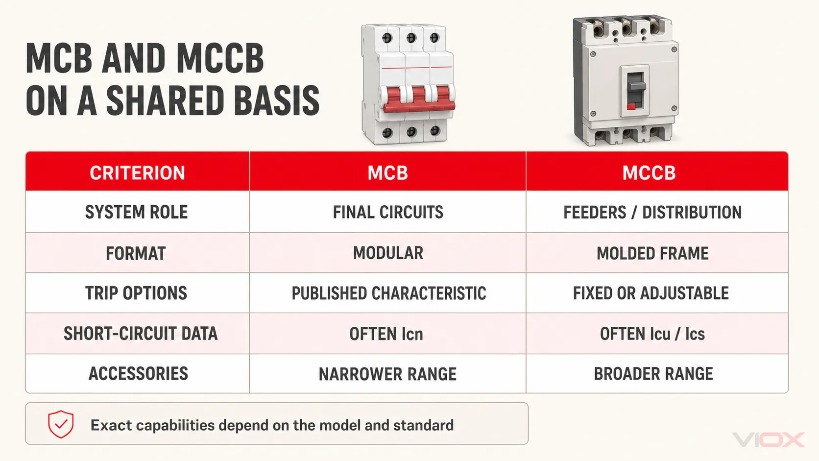
    But even in smaller projects, SPDs become easier to justify when the load includes:

    • control boards
    • communication equipment
    • smart building devices
    • EV charging equipment
    • inverter-driven systems
    • outdoor-connected systems

    This is why “worth it” is not a universal yes-or-no answer. It depends on what is being protected, how exposed the site is, and what failure would really cost.
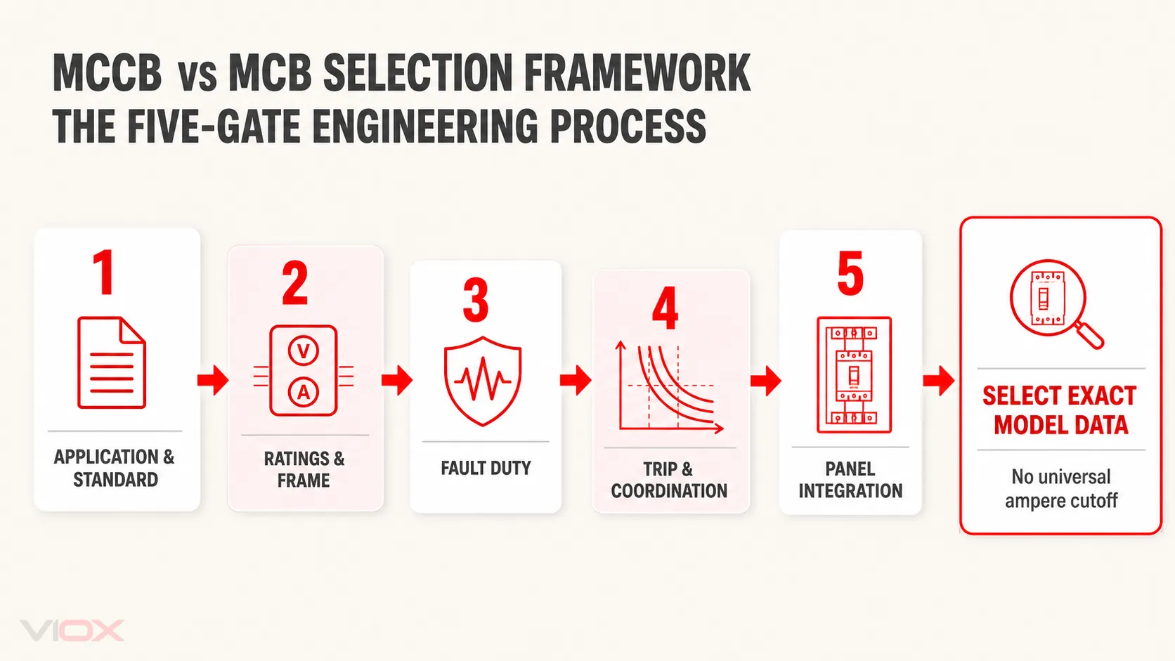
    A Practical Buying Checklist

    Before deciding that the advantages outweigh the disadvantages, check these points:

    Buying question Why it matters
    What surge sources are realistic at this site? Lightning exposure, switching surges, and feeder length affect protection strategy
    What equipment are you actually trying to protect? The value and sensitivity of downstream loads determine the return on protection
    Is the SPD being selected for the right installation point? Type selection must match panel role and system architecture
    Is the rest of the protection system properly coordinated? SPDs work best as part of a complete design, not as a standalone patch
    Is the installation quality likely to support real performance? Layout, grounding, and correct integration shape real-world results
    Is there a maintenance or inspection plan? SPDs are protective components, not permanent guarantees

    For buyers who want a broader sourcing view, the distributor buying guide is the best bridge from technical selection to procurement.

    What an SPD Does Not Solve

    An SPD is designed to limit transient overvoltage. It does not correct sustained overvoltage, undervoltage, frequency variation, harmonic distortion, poor grounding or bonding, or every other power-quality problem. It also does not replace circuit breakers, fuses, residual-current protection, arc-fault protection, or an external lightning-protection system where one is required.

    Protection should be treated as a coordinated system. A panel SPD can reduce transient stress on downstream circuits and hardwired loads, while a compatible point-of-use protector may add protection near sensitive plug-connected equipment. Neither layer guarantees that equipment will survive every surge, and signal or communication paths need their own compatible protection where applicable.

    Maintenance and end-of-life boundary

    • Check the protection-status indicator rather than assuming output power proves protection is active.
    • Use remote contacts or alarms where continuity of protection is operationally important.
    • Inspect after a known severe event and follow the manufacturer’s replacement instructions.
    • Do not apply a universal replacement age or minimum joule value to every SPD type.

    For household coverage decisions, compare a whole-house SPD with point-of-use surge protection. For condition-based replacement, see how to determine SPD end of life.

    FAQ

    What are the biggest pros of surge protection devices?

    The biggest advantages are reduced transient overvoltage exposure, better protection for sensitive electronics, and stronger overall system reliability when the SPD is correctly selected and installed.

    What are the biggest cons of surge protection devices?

    The biggest disadvantages are that they do not solve every electrical problem, they depend on correct system design, and they can lose effectiveness over time if the wrong device is selected or the installation is poorly executed.

    Are surge protection devices worth it?

    They are often worth it when the installation includes expensive electronics, exposed distribution paths, or costly downtime risk. They are less compelling when the site has low exposure, low equipment value, and no meaningful consequence from a surge-related failure.

    Do SPDs protect against lightning?

    SPDs can help limit surge energy associated with lightning-related events, but they are not a complete lightning-protection system by themselves. For that specific question, see lightning protection limits.

    What can an SPD not protect against?

    An SPD does not replace breakers, fuses, grounding, or general wiring quality. It also does not solve overloads, undervoltage, or every kind of electrical disturbance. It is also not a protective answer to sustained overvoltage or TOV conditions. Those conditions can actually overstress and destroy an SPD, especially MOV-based designs, if the device is exposed beyond its intended operating limits.

    Is a Type 2 SPD enough on its own?

    Sometimes, but not always. In many facilities, a Type 2 SPD is appropriate at the panel level. In others, coordinated protection across multiple stages is a better choice. That depends on exposure level, service entrance conditions, and downstream equipment sensitivity.

    Do surge protection devices need replacement?

    They should not be treated as permanent protection without inspection. SPDs can degrade after repeated exposure, so replacement decisions should follow product condition, indicator status, site history, and manufacturer guidance. Related reading: end-of-life warning signs and SPD lifespan.

  • How Does an Electrical Transformer Work

    How Does an Electrical Transformer Work

    Every time you plug your smartphone charger into the wall, charge your laptop, or flip a light switch, you’re relying on one of the most ingenious electrical devices ever invented: the transformer. These silent workhorses of the electrical world make it possible for the high-voltage electricity traveling through power lines to safely power the devices in your home.

    But how does an electrical transformer work? The answer lies in a fascinating principle discovered nearly 200 years ago that continues to power our modern world. In this comprehensive guide, you’ll discover exactly how transformers work, why they’re essential for electrical power distribution, and how the principle of electromagnetic induction makes it all possible.

    Whether you’re a student learning about electrical engineering, a curious homeowner, or a professional seeking a refresher, this guide will take you from basic concepts to advanced applications—all explained in clear, accessible language.

    The Simple Answer: Transformers Use “Magnetic Magic”

    10kv 200kva Oil-immersed Power Transformer

    Think of voltage like water pressure in your pipes. Just as you might need a pressure reducer to safely connect a garden sprinkler to a high-pressure main line, electrical transformers work by changing voltage levels to make electricity safe and usable for different applications.

    Here’s the simple version: transformers use electromagnetic induction to transfer electrical energy from one circuit to another while changing the voltage. They accomplish this remarkable feat without any moving parts, using only the invisible force of magnetism to “step up” or “step down” voltage levels.

    The “magic” happens when alternating current flowing through one coil of wire creates a changing magnetic field that induces voltage in a second, completely separate coil. No direct electrical connection needed—just the power of electromagnetic induction discovered by Michael Faraday in 1831.

    But here’s where it gets interesting: the exact voltage change depends on a simple ratio of wire turns between the two coils. More turns means higher voltage; fewer turns means lower voltage. This elegant simplicity has made transformers indispensable for over a century.

    The Foundation: Understanding Electromagnetic Induction

    To truly understand how electrical transformers work, we need to go back to 1831 when British scientist Michael Faraday made a discovery that would revolutionize the world. Faraday noticed something remarkable: when he moved a magnet through a coil of copper wire, an electric current flowed through that wire.

    This phenomenon, called electromagnetic induction, forms the beating heart of every transformer, generator, and electric motor on Earth.

    Picture this simple experiment: Take a coil of copper wire connected to a sensitive current meter (a galvanometer). When the coil just sits there next to a stationary magnet, nothing happens. But the moment you move that magnet toward or away from the coil, the meter springs to life, showing that current is flowing.

    Here’s the key insight: It’s not the magnetic field itself that creates electricity—it’s the changing magnetic field. When the magnetic field through a conductor changes, it induces an electromotive force (EMF) that pushes electrons through the wire, creating current.

    This is why transformers work with alternating current (AC) but not direct current (DC). AC naturally creates a constantly changing magnetic field, while DC creates a static field that can’t induce current in secondary coils.

    Faraday’s Law Made Simple

    Faraday’s law tells us that the voltage induced in a coil depends on how fast the magnetic field changes and how many turns of wire are in the coil. In mathematical terms:

    Induced Voltage = Rate of Change of Magnetic Flux × Number of Turns

    Don’t worry about the math—the important concept is this: faster changes create higher voltages, and more wire turns also create higher voltages. This relationship is exactly what allows transformers to control output voltage by adjusting the number of turns in their coils.

    How Electrical Transformers Actually Work: Step-by-Step Process

    Now that you understand electromagnetic induction, let’s explore exactly how an electrical transformer works through its four essential components and step-by-step process.

    The Essential Components

    Every transformer consists of three crucial parts working in perfect harmony:

    Primary Winding (Input Coil): This coil receives the input electrical power. When AC voltage is applied here, it creates a changing magnetic field around the coil. Think of this as the “sender” that converts electrical energy into magnetic energy.

    Secondary Winding (Output Coil): This completely separate coil “receives” the magnetic energy and converts it back into electrical energy at a different voltage level. There’s no direct electrical connection between primary and secondary—only the invisible magnetic link.

    Iron Core (Magnetic Highway): The iron core acts like a magnetic superhighway, efficiently channeling the magnetic field from the primary to the secondary coil. Without this core, most of the magnetic energy would scatter into the air and be lost.

    The 4-Step Transformation Process

    Here’s exactly what happens inside a transformer when you plug in a device:

    Step 1: AC Power Enters the Primary Coil

    When alternating current flows through the primary winding, it creates a magnetic field around the coil. Because AC constantly changes direction—typically 60 times per second in North America—this magnetic field is constantly growing, shrinking, and reversing direction. Imagine an electromagnet that turns on and off and flips polarity 120 times every second.

    Step 2: Magnetic Field Travels Through the Iron Core

    The iron core serves as a magnetic highway, efficiently channeling this changing magnetic field from the primary coil to the secondary coil. Iron is chosen because it’s ferromagnetic—meaning it can concentrate and direct magnetic fields much better than air. This dramatically improves the transformer’s efficiency.

    The core is made of thin, insulated steel laminations (typically 0.25-0.5mm thick) rather than solid iron. These laminations prevent energy-wasting eddy currents from forming in the core material.

    Step 3: Secondary Coil “Catches” the Magnetic Energy

    As the changing magnetic field passes through the secondary coil, Faraday’s law kicks in. The changing magnetic flux induces a voltage in the secondary winding, even though there’s no direct electrical connection between the coils. It’s like wireless energy transfer through magnetism.

    Step 4: Output Voltage Depends on Turn Ratios

    Here’s where the transformer’s voltage-changing magic happens. The output voltage is determined by the ratio of turns between the secondary and primary coils:

    • More turns on secondary = Higher output voltage (step-up transformer)
    • Fewer turns on secondary = Lower output voltage (step-down transformer)
    • Equal turns = Same voltage (isolation transformer)

    For example, if the primary has 100 turns and the secondary has 200 turns, the output voltage will be exactly double the input voltage. If the secondary has only 50 turns, the output will be half the input voltage.

    The Conservation of Energy: While transformers can change voltage, they can’t create energy. If voltage goes up, current goes down proportionally, keeping the total power (voltage × current) essentially constant (minus small losses).

    Why Transformers Need AC Current (Not DC)

    One of the most important things to understand about how electrical transformers work is why they absolutely require alternating current to function.

    Remember Faraday’s discovery: changing magnetic fields induce electrical current. The key word here is “changing.”

    With DC Current: Direct current flows in one direction at a constant rate. When you first apply DC to a transformer’s primary winding, there’s a brief moment of change that induces a small current in the secondary. But once the current stabilizes, the magnetic field becomes constant—and constant magnetic fields don’t induce current. The transformer essentially stops working.

    With AC Current: Alternating current constantly changes direction, typically 50-60 times per second. This creates a continuously changing magnetic field that keeps inducing current in the secondary winding. The transformer operates continuously and efficiently.

    This is why your car needs a special inverter to run AC devices from its 12V DC battery, and why the electrical grid uses AC power for transmission and distribution. Transformers and AC current are perfect partners, making efficient electrical power distribution possible.

    Step-Up vs Step-Down Transformers: The Turn Ratio Secret

    The beauty of how electrical transformers work lies in their incredible versatility. The same basic principle can either increase or decrease voltage, depending entirely on the ratio of wire turns between the coils.

    Step-Up Transformers (Voltage Increase)

    Step-up transformers have more turns on the secondary coil than the primary coil. When you need to increase voltage, you use more turns on the output side.

    Common Applications:

    • Power transmission: Converting power plant output (typically 25,000V) to high-voltage transmission lines (up to 765,000V)
    • Audio amplifiers: Boosting signal voltages for powerful speakers
    • Voltage converters: Allowing US appliances (110V) to work in European countries (220V)

    Real-World Example: A power plant might use a transformer with 1,000 turns on the primary and 10,000 turns on the secondary to step up 25,000V to 250,000V for efficient long-distance transmission.

    Step-Down Transformers (Voltage Decrease)

    Step-down transformers have fewer turns on the secondary than the primary. These are probably the most common transformers you encounter daily.

    Common Applications:

    • Neighborhood distribution: Reducing transmission line voltage (thousands of volts) to household voltage (120V/240V)
    • Electronic device chargers: Converting household voltage to the 5V, 9V, or 12V needed by phones, laptops, and other devices
    • Industrial equipment: Providing safe, low voltages for control circuits

    Real-World Example: The cylindrical transformer on the power pole outside your house might have 7,200 turns on the primary (connected to the 7,200V distribution line) and only 240 turns on the secondary (providing 240V to your home).

    The Mathematics Made Simple

    The relationship between turns and voltage is beautifully simple:

    Voltage Ratio = Turn Ratio

    If the secondary has twice as many turns as the primary, the output voltage will be twice the input voltage. If the secondary has half as many turns, the output voltage will be half the input voltage.

    But here’s the trade-off: When voltage goes up, current goes down proportionally. When voltage goes down, current goes up. This maintains the conservation of energy—transformers can’t create power from nothing.

    Formula: Primary Voltage ÷ Secondary Voltage = Primary Turns ÷ Secondary Turns

    This elegant simplicity has made transformers the backbone of electrical power distribution for over a century.

    Transformer Construction: Why Design Matters

    Transformer Construction

    Understanding how electrical transformers work requires appreciating the clever engineering that makes them so efficient and reliable. Every aspect of transformer construction is optimized to maximize energy transfer while minimizing losses.

    The Iron Core: Magnetic Superhighway

    The transformer core is the critical component that makes efficient energy transfer possible. Here’s why design matters:

    Why Iron? Iron is ferromagnetic, meaning it can concentrate magnetic fields thousands of times better than air. This high magnetic permeability creates a low-resistance path for magnetic flux, dramatically improving transformer efficiency.

    Laminated vs. Solid Core: Early transformers used solid iron cores, but engineers quickly discovered a major problem: eddy currents. When solid conductors are exposed to changing magnetic fields, circular currents form within the material, generating heat and wasting energy.

    The solution? Laminated cores made from thin sheets (0.25-0.5mm thick) of silicon steel, each insulated from its neighbors by a thin oxide coating or varnish. These laminations:

    • Dramatically reduce eddy current formation
    • Minimize core heating and energy loss
    • Improve overall transformer efficiency to 95-99%
    • Allow for better heat dissipation

    Silicon Steel: Modern transformer cores use silicon steel rather than pure iron. The silicon increases electrical resistivity, further reducing eddy currents while maintaining excellent magnetic properties.

    Winding Techniques and Materials

    Copper Wire Advantages: Transformer windings use copper wire because copper offers the best combination of electrical conductivity, thermal properties, and cost. Some large transformers use aluminum wire for cost savings, but copper remains the premium choice.

    Insulation Importance: Each layer of windings must be perfectly insulated to prevent short circuits. Modern transformers use sophisticated insulation systems including:

    • Enamel coating on individual wires
    • Paper or polymer insulation between layers
    • Oil or gas insulation in large power transformers

    Heat Management: Transformers generate heat during operation, primarily from resistance in the windings and magnetic losses in the core. Effective cooling systems—from simple air circulation to complex oil cooling systems—are essential for reliable operation.

    Core Types and Shapes

    E-I Laminations: The most common transformer construction uses E-shaped and I-shaped laminations stacked alternately. The E pieces form the main body, while the I pieces close the magnetic circuit. This design provides excellent magnetic coupling while allowing easy assembly.

    Toroidal Cores: Ring-shaped (toroidal) cores offer several advantages:

    • Minimal magnetic flux leakage
    • Compact, efficient design
    • Quiet operation
    • Lower electromagnetic interference

    Shell vs. Core Type:

    • Core type: Windings wrapped around the core legs (most common for distribution transformers)
    • Shell type: Core surrounds the windings (preferred for high-power applications)

    Each design has specific advantages depending on the application, voltage level, and power requirements.

    Types of Transformers and Their Applications

    The principle of how electrical transformers work applies to many different transformer types, each optimized for specific applications.

    Power Transformers

    Power Transformers

    Power transformers handle the bulk electrical energy transfer in the power grid:

    Transmission Transformers: Step up power plant output to high transmission voltages (115kV to 765kV) for efficient long-distance transport. These massive units can weigh hundreds of tons and handle hundreds of megawatts.

    Distribution Transformers: The familiar cylindrical or pad-mounted transformers that step down voltage for neighborhoods and buildings. These workhorses of the electrical grid convert medium-voltage distribution lines (typically 4kV-35kV) to usable voltages (120V-480V).

    Substation Transformers: Large transformers that interface between transmission and distribution systems, often stepping down from transmission voltage levels to distribution levels.

    Isolation Transformers

    10KW-Single-Phase-Isolation-Transformer

    Isolation transformers provide electrical safety by eliminating direct connection between input and output circuits, even when voltage levels remain the same:

    Medical Equipment: Hospitals use isolation transformers to protect patients from electrical shock, especially in areas where medical devices contact patients directly.

    Sensitive Electronics: Laboratory and testing equipment often requires isolation transformers to eliminate ground loops and electrical noise from the power source.

    Safety Applications: Industrial environments use isolation transformers to protect workers and equipment from dangerous ground faults.

    Instrument Transformers

    Current Transformers

    Current Transformers (CTs): Step down high currents to safe, measurable levels for protective relays and metering equipment. These allow power grid monitoring without directly handling dangerous high currents.

    Voltage Transformers (VTs): Step down high voltages to safe levels for measurement and protection systems. Essential for monitoring power grid conditions.

    Combined Instrument Transformers: Some applications use transformers that provide both current and voltage transformation in a single unit.

    Specialty Transformers

    Audio Transformers: Optimized for audio frequency response, these transformers provide impedance matching and isolation in high-quality audio equipment.

    Pulse Transformers: Designed to handle rapid voltage changes, these are essential in digital electronics and switching power supplies.

    Auto-transformers: Single-winding transformers that are more compact and efficient than two-winding types, commonly used in voltage regulators and variable voltage supplies.

    Common Transformer Problems and Solutions

    Understanding how electrical transformers work also means recognizing when they’re not working properly. Here are the most common issues:

    Overheating Problems

    Symptoms: Hot transformer surfaces, burning smells, oil leaks in large transformers

    Causes: Overloading, poor ventilation, insulation breakdown, excessive ambient temperature

    Solutions: Load reduction, improved cooling, professional inspection and maintenance

    Core Saturation

    Symptoms: Excessive heating, distorted output waveforms, loud humming or buzzing

    Causes: Overvoltage conditions, DC component in AC supply, improper transformer sizing

    Solutions: Voltage regulation, DC blocking, properly sized transformer selection

    Insulation Breakdown

    Symptoms: Electrical arcing, ground faults, reduced insulation resistance

    Causes: Age, moisture ingress, thermal stress, electrical overstress

    Solutions: Professional testing, moisture removal, insulation replacement or transformer replacement

    Maintenance Tips

    • Visual inspection: Regular checks for physical damage, oil leaks, overheating signs
    • Electrical testing: Annual insulation resistance and turns ratio testing for critical applications
    • Temperature monitoring: Ensuring proper cooling and ventilation
    • Load monitoring: Preventing chronic overloading that shortens transformer life

    Real-World Applications You Use Every Day

    The principle of how electrical transformers work touches virtually every aspect of modern life:

    Phone and Laptop Chargers: These compact switching power supplies use high-frequency transformers to efficiently convert AC wall power to the DC voltages your devices need. The higher frequency allows much smaller, lighter transformers than traditional 60Hz designs.

    Microwave Ovens: Use high-voltage transformers to convert household 120V to the 2,000-4,000V needed by the magnetron that generates microwaves. These transformers are specifically designed to handle the high-voltage, high-current demands of microwave generation.

    Car Ignition Systems: Modern vehicles use ignition transformers (ignition coils) to convert the car’s 12V battery power to the 10,000-50,000V needed to create spark plugs’ electrical arcs.

    Power Grid Infrastructure: Every time you flip a light switch, your electricity has likely passed through 4-6 different transformers:

    1. Step-up transformer at the power plant
    2. Transmission substation transformers
    3. Distribution substation transformers
    4. Neighborhood distribution transformer
    5. Possibly building-specific transformers for large facilities

    Audio Equipment: High-end audio systems use transformers for impedance matching, noise isolation, and signal coupling. These audio transformers are specially designed to preserve sound quality across the entire audible frequency range.

    Welding Equipment: Arc welders use transformers to convert standard electrical supply to the high-current, controlled-voltage output needed for welding. These robust transformers must handle extreme electrical and thermal stress.

    Energy Efficiency and Losses in Transformers

    Modern electrical transformers work with remarkable efficiency—typically 95-99%—but understanding the small losses helps appreciate their sophisticated design.

    Types of Transformer Losses

    Copper Losses (I²R Losses): Heat generated by electrical resistance in the windings. These losses increase with current load and can be minimized by using larger conductors and optimal winding design.

    Iron Core Losses: Energy lost in the magnetic core material, consisting of:

    • Hysteresis losses: Energy required to repeatedly magnetize and demagnetize the core
    • Eddy current losses: Circular currents induced in the core material (minimized by laminations)

    Stray Losses: Energy lost to electromagnetic fields that don’t contribute to power transfer. Careful design minimizes these through proper magnetic shielding and winding configuration.

    Efficiency Improvements

    Modern transformer design incorporates numerous efficiency improvements:

    • Amorphous steel cores: Newer magnetic materials with lower core losses
    • Optimized winding designs: Computer-designed conductor layouts that minimize resistance and stray losses
    • Advanced cooling systems: Better heat removal allows higher power density and efficiency
    • Load tap changers: Automatic voltage regulation systems that maintain optimal efficiency across varying load conditions

    Energy Conservation Benefits

    High-efficiency transformers provide enormous energy savings when deployed across the electrical grid. A 1% efficiency improvement in distribution transformers saves billions of kilowatt-hours annually in a large power grid—enough to power hundreds of thousands of homes.

    Advanced Concepts: Beyond the Basics

    For those interested in deeper understanding of how electrical transformers work, several advanced concepts expand on the basic principles:

    Three-Phase Transformers

    Most power grid applications use three-phase electricity for more efficient power transmission. Three-phase transformers either use three separate single-phase transformers or a single three-phase unit with three sets of windings on a common core.

    Advantages of Three-Phase Systems:

    • More efficient power transmission
    • Smoother power delivery
    • Better motor performance
    • Reduced conductor requirements

    Auto-Transformers

    Auto-transformers use a single winding that serves as both primary and secondary, with electrical connections at different points along the winding. This design is more compact and efficient than separate-winding transformers but provides no electrical isolation.

    Applications: Voltage regulators, motor starters, three-phase to two-phase conversion

    Variable Transformers

    Variable transformers (like Variac® units) allow continuous voltage adjustment by varying the connection point on the transformer winding. These are essential for testing equipment and applications requiring precise voltage control.

    High-Frequency Transformers

    Modern electronics increasingly use high-frequency transformers (operating at thousands or millions of Hz rather than 60Hz). Higher frequencies allow much smaller transformer cores and improved efficiency in switching power supplies.

    Applications: Computer power supplies, LED drivers, wireless charging systems, power inverters

    Frequently Asked Questions

    Installation and Technical Questions

    Q: What does it mean when H and X terminals are marked on transformers?

    A: H terminals signify high voltage connections while X terminals signify lower voltage connections. A common misconception is that H terminals are always primary and X terminals secondary—this is true for step-down transformers, but in step-up transformers the connections should be reversed.

    Q: Can a single-phase transformer be converted to three-phase power?

    A: No. Phase converters or phase shifting devices such as reactors and capacitors are required to convert single phase power to three phases. You need either three separate single-phase transformers or a purpose-built three-phase transformer.

    Q: What causes loud or unusual noises in transformers?

    A: Transformer noise is caused by magnetostriction, which causes magnetic sheet steel to extend when magnetized and contract when demagnetized. Extensions and contractions occur erratically across the core sheets during each AC cycle, creating vibration and noise. Excessive noise may indicate loose components, overloading, or core problems requiring professional inspection.

    Q: Why can’t transformers above 1kVA be easily back-fed (used in reverse)?

    A: Back feeding larger transformers can result in high inrush currents upon transformer energization and nuisance tripping of circuit breakers and fuses. This issue is difficult to predict and costly to fix. It’s better to purchase transformers specifically wound as step-up units for reverse applications.

    Transformer Oil and Maintenance

    Q: How long do transformers typically last?

    A: A general transformer lifespan can range between 20 and 40 years depending on conditions, from the quality of components to maintenance practices. Some transformers have served for decades with no major problems, while others experience premature wear due to environmental factors or poor maintenance.

    Q: What are the main factors that shorten transformer life?

    A: The three components that determine transformer lifespan are heat, moisture and oxygen. For every 10°C increase in operating temperature, the oxidation byproducts that attack the cellulose paper double. Proper cooling and avoiding overloading are essential for longevity.

    Q: How often should transformer oil be tested?

    A: SDMyers recommends annual testing of dielectric liquid samples to provide critical data to pinpoint issues, diagnose potential problems, and prevent failures. The standardization of NFPA 70B in 2023 means annual liquid sampling and testing is now a minimum requirement for transformer maintenance. Critical equipment may require more frequent testing.

    Q: What environmental conditions should be avoided when collecting oil samples?

    A: Cold conditions, or conditions when relative humidity is in excess of 70 percent, should be avoided, as this will increase moisture in the sample. The ideal situation is 95°F (35°C) or higher, zero percent humidity and no wind.

    Q: What does transformer oil actually do?

    A: Transformer oil serves three key functions: it’s an excellent dielectric medium for insulating components, a good heat transferring agent to dissipate heat from windings to tank walls and radiators, and it’s still the cheapest fluid available for transformer applications.

    Safety and Installation Issues

    Q: What happens if a transformer secondary isn’t properly grounded?

    A: If the secondary of the transformer is not grounded properly, the output voltage will look ok between the phases but it will float and not be referenced to earth ground. This creates safety hazards and measurement issues.

    Q: Do all transformers need vibration pads?

    A: All transformers vibrate at 120 Hz because of the electromagnetic field in the core. These vibrations and audible noise can transfer through the floor; vibration pads and isolators help minimize this issue in commercial applications.

    Q: Can transformers overheat from harmonic distortion?

    A: Due to the prevalence of non-linear loads and the harmonics they produce, transformers can overheat if not specified properly. Modern electronic loads create harmonics that can cause additional heating beyond the nameplate rating.

    Performance and Efficiency

    Q: What is voltage regulation in transformers?

    A: Voltage regulation in transformers is the difference between the full load voltage and the no load voltage, usually expressed in terms of percentage. Good regulation means the output voltage remains stable under varying load conditions.

    Q: What is temperature rise in transformers?

    A: Temperature rise in a transformer is the average temperature of the windings and oil & insulation above the existing ambient temperature. This specification indicates how much heat the transformer generates during normal operation.

    Q: How much can proper maintenance reduce transformer failure rates?

    A: Proper maintenance can reduce failure rates by over 40%, extend equipment lifespan, and prevent catastrophic breakdowns. Regular maintenance provides enormous cost savings compared to emergency repairs or replacements.

    Troubleshooting and Diagnostics

    Q: What should you check first when a transformer isn’t working?

    A: If the transformer can be energized, measure output voltage with no load on transformer to ensure voltage is within tolerance. If a neutral is derived on the load side, ensure that neutral ground bonding is accomplished according to National Electric Code requirements.

    Q: What are the warning signs of transformer problems?

    A: Strange or loud noises are typically caused by vibrations where components are rattling more than usual, indicating loose screws or perhaps even a lack of oil. Smoke is usually caused by exposed wires, which create sparks forming smoke.

    Q: What does dissolved gas analysis (DGA) tell you about transformer health?

    A: DGA testing identifies dissolved gases in oil such as acetylene, methane, hydrogen, ethane, ethylene, oxygen and carbon monoxide. Different gas combinations indicate specific types of internal problems, allowing predictive maintenance before failures occur.

    Q: How often should you perform visual inspections?

    A: Monthly visual inspections, semi-annual oil analysis, annual electrical testing, and continuous monitoring of cooling systems form the backbone of effective transformer maintenance programs.

    Practical Applications

    Q: Why do power companies use such high transmission voltages?

    A: Higher transmission voltages dramatically reduce current for the same power level, which minimizes I²R losses in the transmission lines. This makes long-distance power transmission economical and efficient, but requires transformers to step the voltage back down for safe use.

    Q: Can transformers be installed indoors without special considerations?

    A: Indoor transformers need adequate ventilation for cooling, proper electrical clearances, and may require special enclosures (NEMA ratings) depending on the environment. Oil-filled transformers may need additional fire protection systems and containment for environmental protection.

    Q: What size transformer do I need for my application?

    A: Transformer sizing depends on the total connected load, power factor, starting currents of motors, and potential future expansion. A general rule is to size the transformer at 125% of the calculated load, but consult with electrical professionals for specific applications to ensure proper sizing and code compliance.

    Conclusion

    Understanding how electrical transformers work reveals one of humanity’s most elegant engineering solutions. Through the simple yet profound principle of electromagnetic induction, transformers enable our entire electrical infrastructure—from massive power plants to the smartphone charger beside your bed.

    The next time you plug in a device or flip a light switch, you’ll appreciate the invisible chain of transformers that make modern electrical power possible. From Michael Faraday’s 1831 discovery to today’s ultra-efficient designs, transformers continue to be the silent heroes that power our world.

    Whether you’re a student, professional, or curious learner, grasping these fundamental concepts opens the door to understanding countless other electrical and electronic systems. The principle of electromagnetic induction that powers transformers also drives generators, motors, wireless chargers, and countless other technologies that shape our daily lives.

    Ready to explore more electrical engineering concepts? Understanding transformers provides an excellent foundation for learning about power systems, electrical machines, and the fascinating world of electromagnetism that surrounds us every day.

  • MCB vs MCCB: Key Differences, Ratings, and How to Choose

    MCB vs MCCB: Key Differences, Ratings, and How to Choose

    An MCB (Miniature Circuit Breaker) and an MCCB (Molded Case Circuit Breaker) both provide overcurrent protection, but they are optimized for different system duties.

    MCBs generally serve compact final circuits with published, factory-set operating characteristics. MCCBs generally serve feeders, distribution circuits, and equipment circuits that need larger frames, broader interrupting-performance options, adjustable or electronic trip functions, coordination features, and accessories.

    However, there is no universal ampere value at which an MCB automatically becomes an MCCB. Their available ratings can overlap. Choose between them using five gates:

    1. application and applicable product standard;
    2. voltage, load current, conductor, and frame requirements;
    3. prospective short-circuit current and the correct interruption rating;
    4. trip characteristics, coordination, and protection functions;
    5. mounting, terminals, accessories, and panel integration.

    MCB vs MCCB Comparison Table

    Selection dimension MCB MCCB
    Typical system role Final and compact distribution circuits Feeders, mains, distribution, and equipment circuits
    Physical format Modular, commonly DIN-rail mounted Molded frame, commonly fixed or plug-in mounted; exact forms vary
    Current range Product- and standard-dependent; IEC 60898-1 scope extends to 125 A Product-frame dependent, commonly extending to substantially higher currents
    Trip characteristics Usually published as fixed thermal-magnetic characteristics Fixed or adjustable thermal-magnetic, electronic, or other series-specific trip options
    Short-circuit data Often expressed as Icn in an IEC 60898-1 context Commonly expressed as Icu and Ics in an IEC 60947-2 context
    Coordination capability Possible, but constrained by published device characteristics Broader adjustment and time-delay options may support coordination
    Accessories Usually a narrower range Often includes broader auxiliary, alarm, release, operator, interlock, and communication options
    Panel impact High circuit density and modular replacement More space, support, heat, termination, and access planning
    Best reason to choose it The compact device fully satisfies the circuit duty and applicable standard The circuit requires capabilities or integration options unavailable in the candidate MCB
    MCB and MCCB compared across shared engineering criteria

    These are family-level tendencies, not a substitute for a datasheet. A specific MCCB may have a fixed trip unit, while a modular breaker described commercially as an MCB may be evaluated to IEC 60947-2 or carry more than one standard marking.

    The Main Difference Is System Duty, Not Just Size

    The visible size difference reflects a deeper design difference.

    An MCB is normally designed for dense installation in a distribution board. Its compact modular format is well suited to numerous final circuits. The user selects a rated current and a published trip characteristic rather than configuring multiple protection functions in the field.

    An MCCB uses a molded insulating frame that provides more room for the contact system, arc-control system, trip unit, terminals, operating mechanism, and accessories. Different frame sizes can support different current, voltage, interruption, and accessory combinations.

    That larger frame is useful when a circuit needs one or more of the following:

    • higher declared interruption performance at the system voltage;
    • adjustable long-time, short-time, instantaneous, or ground-fault-overcurrent functions, where provided;
    • time-delay or electronic trip functions for coordination;
    • shunt trip, undervoltage release, auxiliary contacts, alarm contacts, motor operation, or interlocking;
    • cable-lug or busbar terminations suited to the panel architecture;
    • a fixed, plug-in, or draw-out integration method offered by the product system.

    Not every MCCB includes every function. Confirm the exact trip unit, frame, accessories, and ratings in the manufacturer’s published documentation.

    Standards: MCB and MCCB Are Not Complete Standard Definitions

    Product-family names and product standards are related, but they are not interchangeable labels.

    IEC 60898-1 context

    IEC 60898-1 applies to AC air-break circuit breakers for household and similar installations within its stated scope: rated voltage not exceeding 440 V between phases, rated current not exceeding 125 A, and rated short-circuit capacity not exceeding 25 kA.

    This defines the scope of the standard. It does not mean every MCB has a 125 A rating or 25 kA short-circuit capacity. Use the markings and certificate or declaration associated with the exact product.

    IEC 60947-2 context

    IEC 60947-2:2024 applies to low-voltage circuit breakers intended to be installed and operated by instructed or skilled persons, within the voltage scope stated by the standard. It is widely used for industrial and switchgear applications.

    MCCBs commonly fall under IEC 60947-2, but the standard also covers circuit breakers that may not fit a simple visual MCCB stereotype. Likewise, some compact or modular breakers are marked to IEC 60947-2.

    For the deeper standards comparison, read IEC 60898-1 vs IEC 60947-2.

    North American context

    North American selection uses different product categories, installation rules, and interruption-rating language. UL Solutions identifies UL 489 as covering molded-case circuit breakers, molded-case switches, and circuit-breaker enclosures, including relevant markings and special product functions.

    Do not treat Icn, Icu, Ics, and a UL interrupting rating as interchangeable labels merely because each is expressed in kA. Verify the applicable standard, voltage, test basis, product marking, and installation requirements.

    Current Rating and Frame Size

    Current rating is necessary, but it is not the first and only dividing line.

    For either device family, the selected rated current and trip characteristic must coordinate with:

    • design current of the circuit;
    • conductor ampacity after applicable correction factors;
    • load starting or inrush behavior;
    • ambient temperature and grouping conditions;
    • continuous loading rules in the target jurisdiction;
    • upstream and downstream protective devices;
    • the device’s declared operating characteristics.

    MCBs are commonly used at the lower-current, final-circuit level because their modular construction is efficient and compact. MCCBs extend across larger frame sizes and usually offer more options for feeder and equipment protection.

    The overlap zone matters. A 63 A or 100 A circuit, for example, cannot be classified correctly from amperes alone. A suitable MCB may exist for one final-circuit application, while another circuit at the same current requires an MCCB because of fault level, trip adjustment, coordination, accessories, terminals, environmental conditions, or the applicable standard.

    Breaking Capacity: Compare the Correct Rating

    A breaker’s short-circuit rating must be adequate for the prospective short-circuit current at its installation point at the relevant system voltage and under the applicable standard.

    Term Common standards context What it communicates
    Icn IEC 60898-1 Rated short-circuit capacity under the test sequence defined by that standard
    Icu IEC 60947-2 Rated ultimate short-circuit breaking capacity under the IEC 60947-2 test sequence
    Ics IEC 60947-2 Rated service short-circuit breaking capacity, expressed in relation to Icu according to the declared product data
    Interrupting rating / AIR North American product context Declared ability to interrupt fault current under the applicable North American standard and marked voltage conditions

    The selection process is not “domestic equals 6 kA” or “industrial equals MCCB.” Determine or obtain the available fault current, then compare it with the correct declared rating at the system voltage.

    Do not apply a universal percentage multiplier and call it a standards rule. Project specifications may require design margin, but the required rating, coordination method, and any permitted series or combination rating depend on the governing system and documentation.

    For the focused MCB decision, see 6 kA vs 10 kA MCB breaking-capacity selection. For broader rating terminology, see Understanding the kA Rating on Circuit Breakers.

    Trip Units, Adjustability, and Coordination

    MCB trip characteristics

    Many AC MCBs use a thermal release for overload response and a magnetic release that operates rapidly when overcurrent reaches its instantaneous pickup range, typically during a short circuit. Published B, C, or D characteristics describe different instantaneous pickup ranges in the relevant IEC context.

    These characteristics are normally selected rather than field-adjusted. The correct curve must allow normal starting or inrush current while still meeting the required fault-protection and disconnection conditions. See Circuit Breaker Trip Curve Explained for curve-reading detail.

    MCCB trip options

    MCCBs may use:

    • fixed thermal-magnetic releases;
    • adjustable thermal-magnetic releases;
    • electronic trip units with a series-specific combination of long-time, short-time, instantaneous, and ground-fault-overcurrent functions.

    Adjustment is valuable only when the settings are engineered and documented. It does not make an MCCB universally “better.” An incorrectly selected or configured trip unit can compromise conductor protection, load starting, selectivity, or equipment protection.

    Selectivity and backup protection

    Selectivity means the protective device closest to the fault clears it while upstream devices remain closed, within the verified limits of the design. Backup or cascading protection uses a tested upstream/downstream combination to achieve a declared short-circuit performance.

    Neither result can be guaranteed from rated current or separate time-current curves alone. Use the exact manufacturer’s selectivity, cascading, or series-rating tables for the named upstream and downstream models, voltage, fault level, and settings. Schneider Electric’s circuit-breaker coordination guidance illustrates why cascading performance belongs to tested device combinations rather than assumptions made from two independent ratings.

    Mounting, Accessories, and Panel Integration

    The breaker must fit the electrical system and the physical assembly.

    Typical MCB integration

    • modular DIN-rail arrangement;
    • comb or pin busbar systems where approved for the exact devices;
    • compact conductor terminals;
    • auxiliary or alarm contacts on supported series;
    • dense final-circuit labeling and distribution.

    Typical MCCB integration

    • fixed, plug-in, or other manufacturer-defined mounting;
    • cable lugs, spreaders, busbar connections, or terminal accessories;
    • additional space for conductors, bending radius, barriers, and heat dissipation;
    • shunt trip, undervoltage release, auxiliary contacts, alarm contacts, rotary mechanisms, motor operators, and interlocks where offered;
    • coordination with the enclosure or switchboard system.

    Do not use generic torque, conductor, lug, clearance, or orientation values. These are model- and installation-specific. Use the exact instruction sheet, terminal data, enclosure documentation, and assembly rules.

    How to Choose Between an MCB and an MCCB: Five Gates

    Five-gate engineering framework for choosing between an MCB and an MCCB

    Gate 1: Application and standard

    Identify the circuit role and target market:

    • household or similar final circuit;
    • commercial distribution circuit;
    • industrial feeder;
    • machine or equipment circuit;
    • main incoming device;
    • North American branch or feeder application;
    • another jurisdiction-specific installation.

    Then identify the product standard and certification or approval required by the project. Do not choose a family name first and try to justify the standard afterward.

    Gate 2: Voltage, current, conductor, and frame

    Record:

    • system voltage, frequency, and AC/DC arrangement;
    • number of poles and neutral treatment;
    • design and continuous current;
    • conductor material, size, installation method, and corrected ampacity;
    • available panel space and mounting system;
    • ambient and enclosure conditions.

    Reject any candidate whose published ratings or physical integration do not match.

    Gate 3: Prospective short-circuit current

    Obtain the prospective fault current at the installation point. Verify the candidate breaker’s declared short-circuit rating at the actual system voltage and under the applicable standard.

    Where selectivity, backup protection, or a series-rated combination is used, require the exact tested manufacturer combination. Do not build a combination from assumptions about two separate products.

    Gate 4: Trip and coordination requirements

    Define:

    • overload protection requirement;
    • instantaneous pickup or curve requirement;
    • starting and inrush current;
    • required selectivity window;
    • need for short-time delay;
    • need for ground-fault-overcurrent functions;
    • required monitoring or communication;
    • settings authority and commissioning process.

    If a fixed MCB characteristic completes the task, an adjustable MCCB may add no useful value. If the circuit needs adjustable or electronic functions unavailable in the MCB range, an MCCB becomes the stronger candidate.

    Gate 5: Terminations, accessories, and service model

    Confirm:

    • terminal and conductor compatibility;
    • approved busbar or lug system;
    • mounting and enclosure compatibility;
    • required auxiliary and control functions;
    • isolation and indication requirements;
    • environmental ratings;
    • test, documentation, replacement, and spare-parts requirements.

    Only after all five gates pass should price and supplier terms decide between compliant candidates.

    Three Selection Examples

    Example 1: Compact final circuit

    A final circuit in a household or similar installation has a suitable corrected conductor ampacity, a known prospective short-circuit current within the candidate device’s declared capacity, and no need for adjustable protection or extensive accessories.

    Likely direction: an appropriately certified and rated MCB. Verify the exact standard, voltage, current rating, curve, poles, short-circuit capacity, and distribution-board compatibility.

    Example 2: Industrial distribution feeder

    A feeder supplies a panel with a higher fault level and requires adjustable long-time and instantaneous response, coordination with downstream devices, auxiliary status contacts, and a rotary operating mechanism.

    Likely direction: an MCCB with the required frame, trip unit, interruption ratings, accessories, and manufacturer coordination data.

    Example 3: The overlap zone

    A 63 A industrial circuit could potentially use a modular breaker or a small-frame MCCB. Current rating alone does not settle the choice.

    Check whether the project requires IEC 60898-1, IEC 60947-2, UL 489, or another approval; compare fault duty, trip functions, terminals, coordination, accessories, and panel construction. The correct answer may be an IEC 60947-2 modular breaker, a fixed-trip MCCB, or an adjustable MCCB depending on those inputs.

    MCB vs MCCB Specification Checklist

    Before requesting a quotation or approving a breaker, provide:

    • target country and required standard or listing;
    • application and circuit role;
    • system voltage, frequency, and AC/DC arrangement;
    • design current and load profile;
    • conductor and termination information;
    • prospective short-circuit current at the installation point;
    • required interruption rating terminology and value;
    • trip characteristic or required adjustable functions;
    • upstream and downstream device models for coordination;
    • poles and neutral treatment;
    • mounting and enclosure system;
    • required releases, contacts, mechanisms, interlocks, monitoring, or communication;
    • environmental and derating conditions.

    For a complete MCCB specification workflow, use the MCCB Selection Guide.

    Frequently Asked Questions

    What is the main difference between MCB and MCCB?

    An MCB is normally a compact modular breaker used for final circuits with published fixed characteristics. An MCCB normally provides a larger molded frame and broader options for current, interruption performance, trip units, coordination, terminals, and accessories. Exact capabilities depend on the product series and standard.

    Is an MCCB better than an MCB?

    No. An MCCB is more capable in some dimensions but is not automatically the better choice. If a compliant MCB satisfies the voltage, current, fault-duty, trip, coordination, and installation requirements, its compact format may be more appropriate.

    At what current should I change from MCB to MCCB?

    There is no universal crossover current. Product ranges overlap. Use the five selection gates rather than a fixed 63 A, 100 A, or 125 A rule.

    Can an MCCB replace an MCB?

    Not as a drop-in substitution. The replacement must be checked for standard and approval, voltage, current, conductor protection, interruption rating, trip characteristics, coordination, mounting, terminals, enclosure, and accessories.

    Which breaker is used as a main breaker?

    Either family may appear in an incoming role within its declared capabilities and the applicable installation rules. MCCBs are common for larger distribution and feeder duties, but “main breaker” alone does not specify the correct product.

    Does an MCCB provide earth-leakage protection?

    Only if the exact product and trip system provide a declared ground-fault or residual-current function. Ordinary overcurrent protection is not a substitute for an RCCB or RCBO where residual-current protection is required. See the MCB, MCCB, RCD, RCCB, and RCBO comparison for the protection-function boundary.

    Compare Published Product Families

    After defining the five selection inputs, compare the published VIOX MCB range and VIOX MCCB range. Final selection should be based on the exact model documentation and the requirements of the target installation.

    Sources