On this page
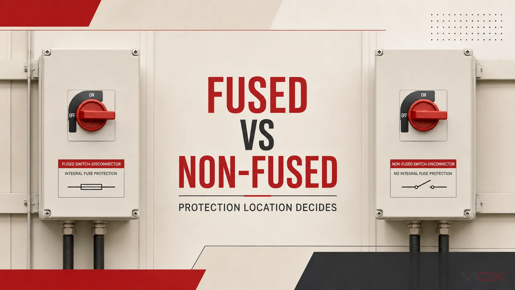
A fused disconnect switch combines a disconnecting function with local fuse holders. A non-fused disconnect switch—also called a non-fusible or unfused disconnect—provides switching or isolation but does not itself provide overcurrent protection.
Choose a fused disconnect when the equipment instructions or protection design requires specified fuses at that location, or when a documented fuse combination is needed for coordination or short-circuit current rating (SCCR). Choose a non-fused disconnect when a correctly rated upstream protective device already performs the required protection and the complete arrangement is suitable for the available fault current.
That is the practical difference. It is not simply “more protection versus less protection”: it is a decision about where protection is located and which tested or documented combination the system uses.
For the wider device family and its role in safe isolation, see what an isolator switch is and how it is selected. This page focuses only on the fused-versus-non-fused decision.
Fused vs Non-Fused Disconnect at a Glance
| Selection point | Fused disconnect | Non-fused disconnect |
|---|---|---|
| Main function | Switching or isolation plus local fuse accommodation | Switching or isolation only |
| Overcurrent protection at the switch | Yes, when the correct fuses are installed | No |
| Protection dependency | Fuse type, rating, characteristics, and approved combination | Upstream breaker or fuse and approved combination |
| SCCR impact | May support a documented higher combination rating, but not automatically | Depends on the switch rating and specified upstream protective device |
| Coordination options | Local fuse characteristics can support selective or current-limiting designs | Coordination is handled mainly by upstream and downstream protective devices |
| Service work | Requires correct replacement fuses and spare-fuse control | No local fuses to replace; upstream protection still requires investigation after a fault |
| Typical reason to choose | Equipment calls for fuses, local branch protection is required, or a fuse combination solves a documented protection need | Protection is already correctly provided upstream and local isolation is the remaining function |
Both devices must still be checked for voltage, current, number of poles, AC or DC duty, load-switching capability, enclosure, environmental conditions, and applicable certification. “Fused” does not automatically mean load-break rated, and “non-fused” does not mean unprotected.
What Is a Fused Disconnect Switch?
A fused disconnect integrates a manually operated switch with fuse positions in one assembly. When properly applied, the switch creates the required disconnected state and the fuses provide overcurrent protection for the circuit or equipment covered by their design.
The two functions must be evaluated separately:
- The switching element must be suitable for the required duty. A device intended only for isolation is not automatically suitable for interrupting normal load current.
- The fuse must have the correct class or type, current rating, voltage rating, interrupting capability, and time-current behavior for the protected circuit.
The assembly’s performance can also depend on the exact fuse. Substituting a different fuse family merely because it fits physically can invalidate coordination assumptions or a published SCCR. For fuse fundamentals, see the VIOX guide to electrical fuse types, operating principles, and selection.
What Is a Non-Fused Disconnect Switch?
A non-fused disconnect switch provides a local means to open the circuit, but it contains no fuses and does not clear overcurrent faults by itself. It must be used within a system that provides the required overcurrent protection elsewhere—commonly through an upstream circuit breaker or fuse.
This architecture can be entirely appropriate. UL Solutions notes, in its guidance on machinery supply circuits, that the supply disconnect does not necessarily need an integral overcurrent protective device; a non-fused UL 98 disconnect can be used where the system architecture provides the required protection separately.
However, “there is a breaker upstream” is not enough information on its own. The breaker type and setting, conductors, equipment instructions, available fault current, switch SCCR, and documented combination all matter. A non-fused disconnect simplifies the local device, but it does not remove protection engineering from the circuit.
If the distinction between isolation, switching, and fault interruption is unclear, start with isolator, disconnector, switch-disconnector, and load-break switch terminology.
The Core Decision: Where Should Overcurrent Protection Be Located?
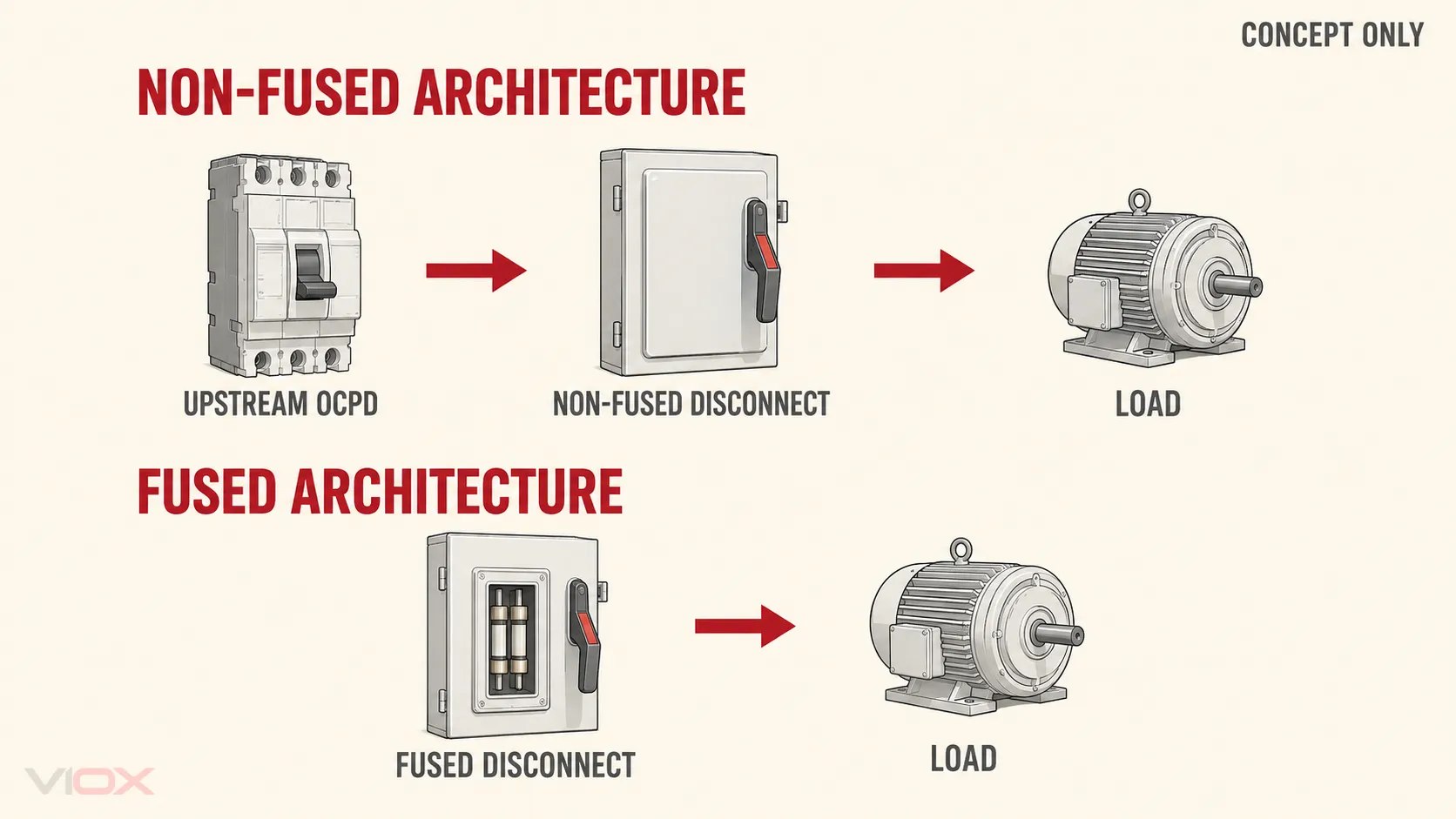
A fused disconnect places fuse protection at the disconnect. A non-fused disconnect separates those functions: the local device disconnects, while another device protects against overcurrent.
This leads to three common architectures:
- Upstream breaker or fuse → non-fused disconnect → load. Use this only when the upstream device correctly protects the conductors and equipment, and the combination meets the required ratings.
- Fused disconnect → load. The local assembly provides the disconnecting function and the specified fuse protection.
- Upstream protection → fused disconnect → load. Two protective levels may be used for coordination, equipment requirements, or branch-circuit design. The devices must be coordinated; adding fuses without a protection objective is not automatically an improvement.
The choice therefore begins with a one-line protection statement: which device protects which conductors and which equipment against which fault condition? If that sentence cannot be completed from the drawings, equipment data, and coordination information, the disconnect type has not yet been selected.
How to Choose: Five Engineering Gates
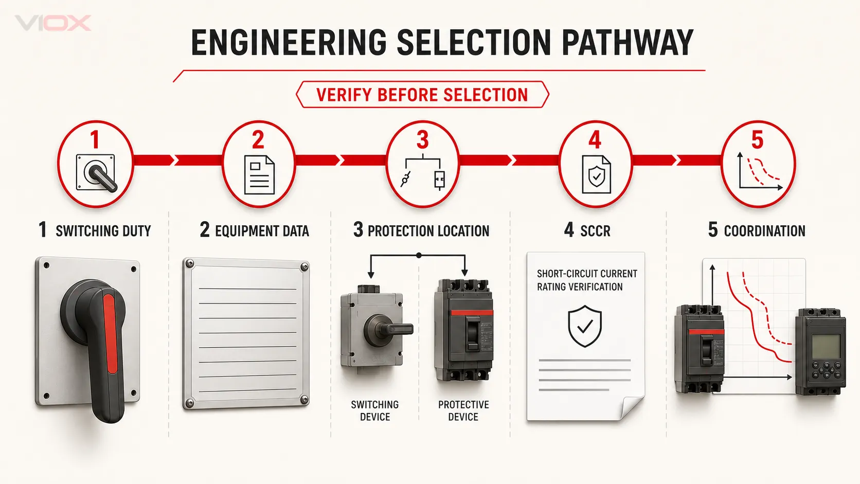
1. Verify the Required Switching and Isolation Duty
First define what the operating device must do. Is it an isolating device operated only after the load is removed, or must it make and break normal load current? Does it serve a motor circuit, resistive heater, mixed distribution load, photovoltaic DC circuit, or another duty?
Under IEC practice, IEC 60947-3 covers switches, disconnectors, switch-disconnectors, and fuse-combination units for low-voltage circuits. The marked utilization category and ratings—not the everyday name “disconnect”—determine the permitted duty. In North American applications, confirm the applicable listing category, such as a UL 98 enclosed or dead-front switch, and any horsepower or application rating required by the design.
This gate is the same for fused and non-fused devices. Fuses do not upgrade an isolator into a load-break switch.
2. Read the Equipment Documentation Before Choosing the Protection Type
Equipment nameplates, installation instructions, and manufacturer tables may specify a maximum protective-device rating, a particular fuse class, an allowed circuit breaker, or a tested combination. Those instructions can decide the fused-versus-non-fused question before cost or convenience is considered.
For example, if a listed equipment configuration is published only with specified fuses, a fused disconnect may be the practical local solution. If the equipment documentation permits a specified upstream circuit breaker and the local device only needs to disconnect, a non-fused switch may be appropriate.
Do not copy the device type from an older installation without checking the current equipment data. Two loads with similar current can have different starting behavior, short-circuit requirements, or manufacturer conditions.
3. Confirm the Protection Location and Scope
Identify the protective device serving the conductors and load. Then verify what protection it provides. Short-circuit and ground-fault protection, overload protection, residual-current protection, and functional control are different duties; one set of fuses does not automatically replace every required protective or control function.
Choose a fused disconnect when local fuses are part of the defined branch or equipment protection. Choose a non-fused disconnect when the required protection is already correctly provided and documented upstream.
For a deeper comparison of devices that disconnect versus devices that automatically interrupt faults, see circuit breaker vs isolator switch.
4. Compare Available Fault Current With the Documented SCCR
The available fault current at the installation point must not exceed the rating of the equipment or approved combination. This check applies to both fused and non-fused disconnects.
A fused assembly may achieve a particular combination SCCR only with a specified fuse class and maximum fuse rating. A non-fused switch may have a documented rating when protected by a specified upstream breaker or fuse. Schneider Electric’s published safety-switch SCCR tables, for example, show that ratings are conditional on the product family and protective-device combination. The lesson is not to borrow Schneider’s values for another product; it is to check the exact manufacturer’s table.
Do not assume that any fused disconnect has a higher SCCR than any non-fused model. Compare the available fault current with the markings and combination data for the exact devices being specified.
5. Check Coordination, Operation, and Maintenance
Protective-device coordination determines which device opens first and how much of the installation is taken offline. Fuse current-limiting behavior and time-current characteristics can be useful in some designs, but the result depends on the selected fuse and the other protective devices. It cannot be inferred from the word “fused.”
Also consider the operating model:
- Will qualified personnel have the correct replacement fuse type and rating available?
- Does the maintenance process prevent unapproved substitutions?
- Is local fault clearing desirable, or is a centralized upstream protective device preferred?
- How will personnel identify and investigate the fault before re-energizing?
- Does the design require visible contact position, door interlocking, padlocking, remote indication, or auxiliary contacts?
These are lifecycle requirements, not reasons to bypass the electrical checks above.
Application Examples
Industrial Machinery
A machine may use a local non-fused disconnect while a correctly selected upstream device provides supply-circuit protection. This separates the isolation and protection functions and can be valid when the machine documentation, conductor protection, available fault current, and applicable certification support the arrangement.
A fused disconnect becomes a stronger candidate when the machine builder specifies a fuse-protected supply combination, needs a documented combination SCCR, or places branch protection at the machine entrance. The UL guidance on machine supply circuits is useful for understanding why integral protection is not universal, but the final machine design still requires its own documented evaluation.
HVAC and Packaged Equipment
For packaged equipment, start with the nameplate and installation instructions. If the documentation specifies a fuse-only protection condition or a fuse class, use the matching approved architecture. If it permits the specified upstream breaker and the local device is only the service disconnect, a non-fused disconnect may satisfy that role.
Avoid the shortcut “HVAC always needs fused” or “an upstream breaker always makes fuses unnecessary.” The equipment’s marked conditions and local installation rules decide.
Distribution and Process Loads
In a distribution panel or process line, a non-fused switch can provide local isolation while upstream protection remains centralized. A fused switch-disconnector can combine local switching and protection where feeder segmentation, coordination, or documented equipment ratings favor that arrangement.
When comparing an integrated fused switching device with a simple fuse carrier, see fuse holder vs fuse switch disconnector. A fuse holder should not be assumed to provide the same operating or isolation function as a rated switch-disconnector.
Common Selection Mistakes
Treating “Fused” as Automatically Safer
A correctly engineered fused design and a correctly engineered non-fused design can both be appropriate. Safety depends on the complete system: ratings, protective-device application, enclosure, installation, operation, and maintenance.
Treating a Non-Fused Disconnect as Fault Protection
A non-fused switch opens when operated; it does not automatically clear a short circuit or overload. The upstream protection must be identified and checked.
Assuming Fuses Guarantee a High SCCR
SCCR is a marked or documented equipment/combination property. It is not created simply by installing fuses. Use the specified fuse and verify the exact manufacturer’s combination table.
Ignoring AC/DC and Load Duty
A switch suitable for one voltage, current type, or utilization category may not be suitable for another. DC interruption is particularly dependent on the device’s marked DC rating and pole arrangement. Never transfer an AC selection directly to DC without manufacturer documentation.
Choosing From Current Rating Alone
Continuous current is only one input. Voltage, poles, switching category, motor or load duty, available fault current, SCCR, enclosure, ambient conditions, terminals, certifications, and operating accessories can all change the correct product.
Specification and RFQ Checklist
Provide the following information when requesting a fused or non-fused disconnect:
- System voltage, frequency, and AC or DC supply
- Number of poles and grounding arrangement
- Continuous current and load type
- Required switching or isolation duty and operating frequency
- Motor, horsepower, utilization-category, or application rating where relevant
- Upstream protective-device type, rating, and setting
- Equipment maximum protective-device or fuse requirements
- Available fault current at the installation point
- Required assembly SCCR or short-circuit rating
- Required fuse class, size, and characteristics if using a fused design
- Enclosure/IP or NEMA requirement and environmental conditions
- Door interlock, padlocking, handle, indication, and auxiliary-contact requirements
- Required IEC, UL, CSA, or market-specific certification
- Manufacturer documentation needed to support the selected combination
If available fault current, coordination, or equipment protection requirements are unknown, resolve those items before ordering. Product selection cannot repair an undefined protection design.
Final Selection Rule
Use a fused disconnect switch when specified local fuses are part of the protection design or a documented fuse combination is required. Use a non-fused disconnect switch when suitable upstream overcurrent protection already exists and the complete arrangement meets the equipment, switching-duty, and fault-current requirements.
The reliable workflow is: verify duty, read the equipment data, define protection location, check SCCR against available fault current, and then assess coordination and maintenance. VIOX supplies switch disconnectors for industrial applications; share the completed checklist with the supplier so the recommendation can be tied to a specific product and documented combination.