On this page
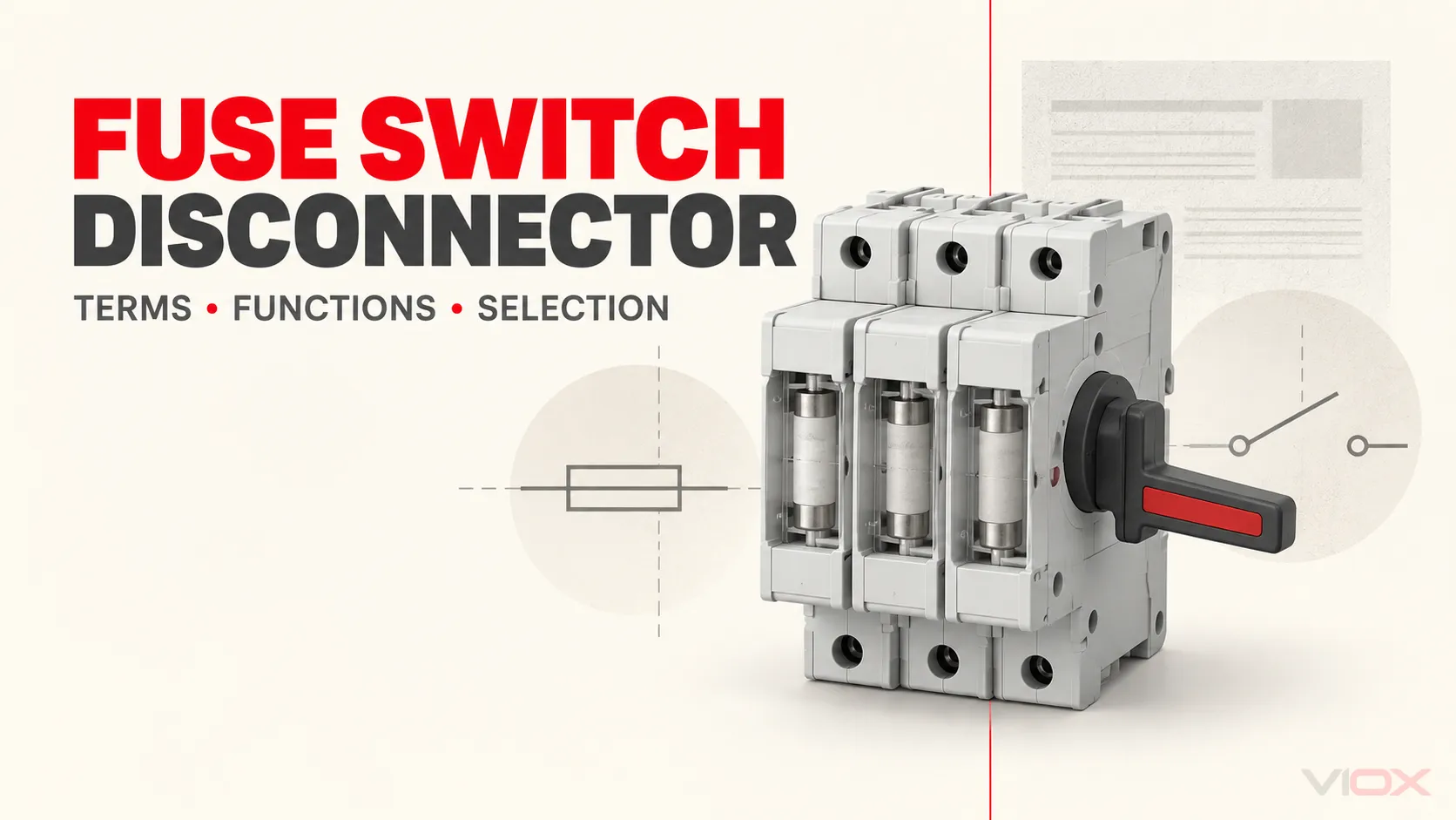
A fuse switch disconnector combines fuse links with a manually operated switching device. When the complete device is correctly declared for all three functions, it can switch normal load current, provide isolation, and use the fuse links to interrupt overcurrents.
The names are less reliable than they appear. Fuse switch, switch fuse, fused switch, fuse disconnector, fuse switch isolator, and fused disconnect switch can refer to related products, but they do not automatically prove the same switching duty, isolation function, fuse system, or market certification. Select from the marked ratings and manufacturer documentation—not from word order alone.
Start With Functions, Not the Product Name
Four electrical functions are often compressed into one commercial label:
| Function | What performs it | What must prove it |
|---|---|---|
| Carry normal current | Contacts, terminals, fuse links, and internal conductors | Rated operational current and voltage for the stated conditions |
| Make or break normal load current | Switching mechanism and contacts | Declared switching duty or utilization category at the required voltage and current |
| Provide isolation | Complete switching device in its open state | Declared disconnector or switch-disconnector function and applicable product documentation |
| Interrupt an overcurrent | Fuse link | Correct fuse category, rated voltage, rated current, breaking capacity, and time-current/let-through data |
The fuse link interrupts currents within its declared operating range and characteristic; some fuse categories provide full-range protection, while others are intended for a limited range. The operating handle opens or closes the switching contacts. These are related functions, but one rating cannot be copied into the other field. A fuse link’s breaking capacity does not prove that the operating mechanism can switch a load, and a switch current rating does not prove that the selected fuse protects the cable or equipment.
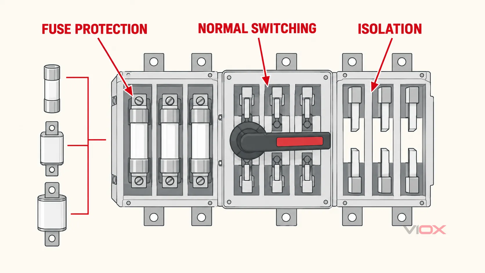
IEC 60947-3:2020, including Amendment 1:2025, covers switches, disconnectors, switch-disconnectors, fuse-combination units, and their dedicated accessories for specified low-voltage distribution and motor-circuit applications. It is therefore the central IEC reference for identifying the switching and isolation function of this product family. The incorporated fuse links also require their own applicable fuse documentation.
Fuse Switch, Switch Fuse, and Fuse Disconnector Terminology
The safest way to read a supplier description is to treat it as a search clue, then confirm the declared function.
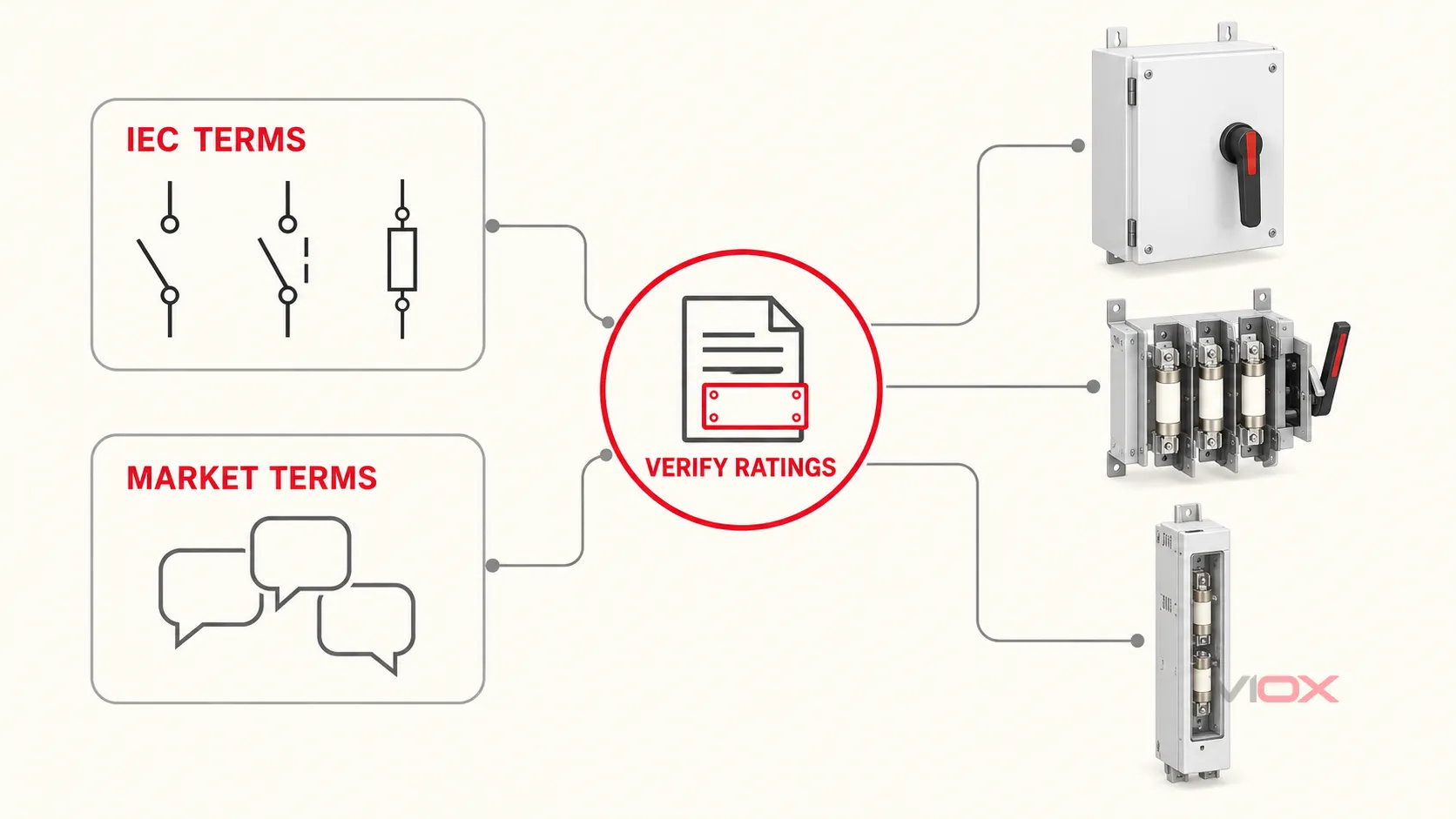
| Term encountered | What it commonly points to | What the name does not prove |
|---|---|---|
| Fuse switch disconnector | An IEC-style fuse-combination unit intended to combine switching, isolation, and fuse protection | Exact utilization category, fuse compatibility, voltage, current, or short-circuit performance |
| Fuse disconnector / fuse isolator | A fuse-combination device emphasizing isolation | Permission to make or break the intended load current |
| Fuse-switch | A recognized IEC fuse-combination term and graphical-symbol name | That every product sold under the term has the same construction or operating duty |
| Switch fuse / switch-fuse | Common UK and commercial wording for a switch used with fuses | Whether the product is a switch, disconnector, or switch-disconnector under the applicable declaration |
| Fused switch | Informal shorthand for a switch incorporating or used with fuses | Isolation capability, load-break duty, or certification route |
| Fused disconnect switch / fusible disconnect | Common North American market wording for a disconnect containing fuses | Equivalence to a specific IEC utilization category or suitability for a particular installation |
The IEC 60617 graphical-symbol catalogue separately identifies symbols for a fuse-switch, fuse-disconnector, and fuse switch-disconnector. That is a useful warning against treating every reordered phrase as a perfect synonym.
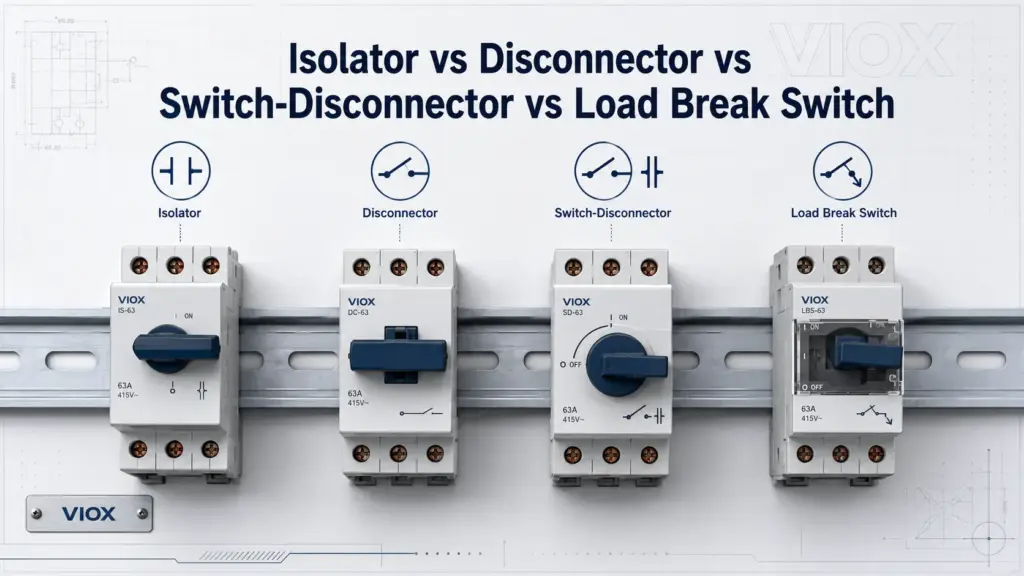
For the underlying distinction between switching and isolation functions without the fuse-combination wording, see the separate guide to isolators, disconnectors, switch-disconnectors, and load-break switches.
In North American equipment, terminology and evaluation routes differ. UL Solutions identifies both fused and unfused disconnect-switch components under UL 98 in its combination motor controller SCCR guidance. The practical lesson is not to translate an IEC name directly into a UL claim. Verify the exact listing, markings, fuse class, enclosure or open-type construction, and combination data required by the project.
What Is the Difference Between a Fuse Holder and a Fuse Switch Disconnector?
A fuse holder primarily supports and electrically connects a fuse link. A fuse switch disconnector adds a declared switching and isolation function to the fuse arrangement.
| Selection question | Fuse holder | Fuse switch disconnector |
|---|---|---|
| Does it accept a replaceable fuse link? | Yes, when designed for that fuse system | Yes, when designed for that fuse system |
| Does the name alone prove normal-load switching? | No | No; verify the declared duty |
| Does the name alone prove isolation? | No | No; verify the declared disconnector function and instructions |
| Is it selected only by fuse ampere rating? | No | No |
| What is the decisive evidence? | Fuse compatibility, holder ratings, access conditions, and instructions | Complete-device ratings, switching duty, isolation declaration, fuse compatibility, and short-circuit evidence |
Physical movement is not the same as rated switching. A carrier may be removable, hinged, or pull-out without being suitable for opening the intended circuit under load. Conversely, a compact fuse-combination device may have a documented switching duty even if its external form resembles a holder. The product marking, declaration, and instructions settle the question.
This boundary also matters in North American applications. UL’s panelboard application guidance notes that simply removing a plug or cartridge fuse from its holder does not provide service disconnection; the required switching function must be provided and evaluated separately.
How to Select a Fuse Switch Disconnector
Use the following sequence to turn an ambiguous product name into a checkable specification.
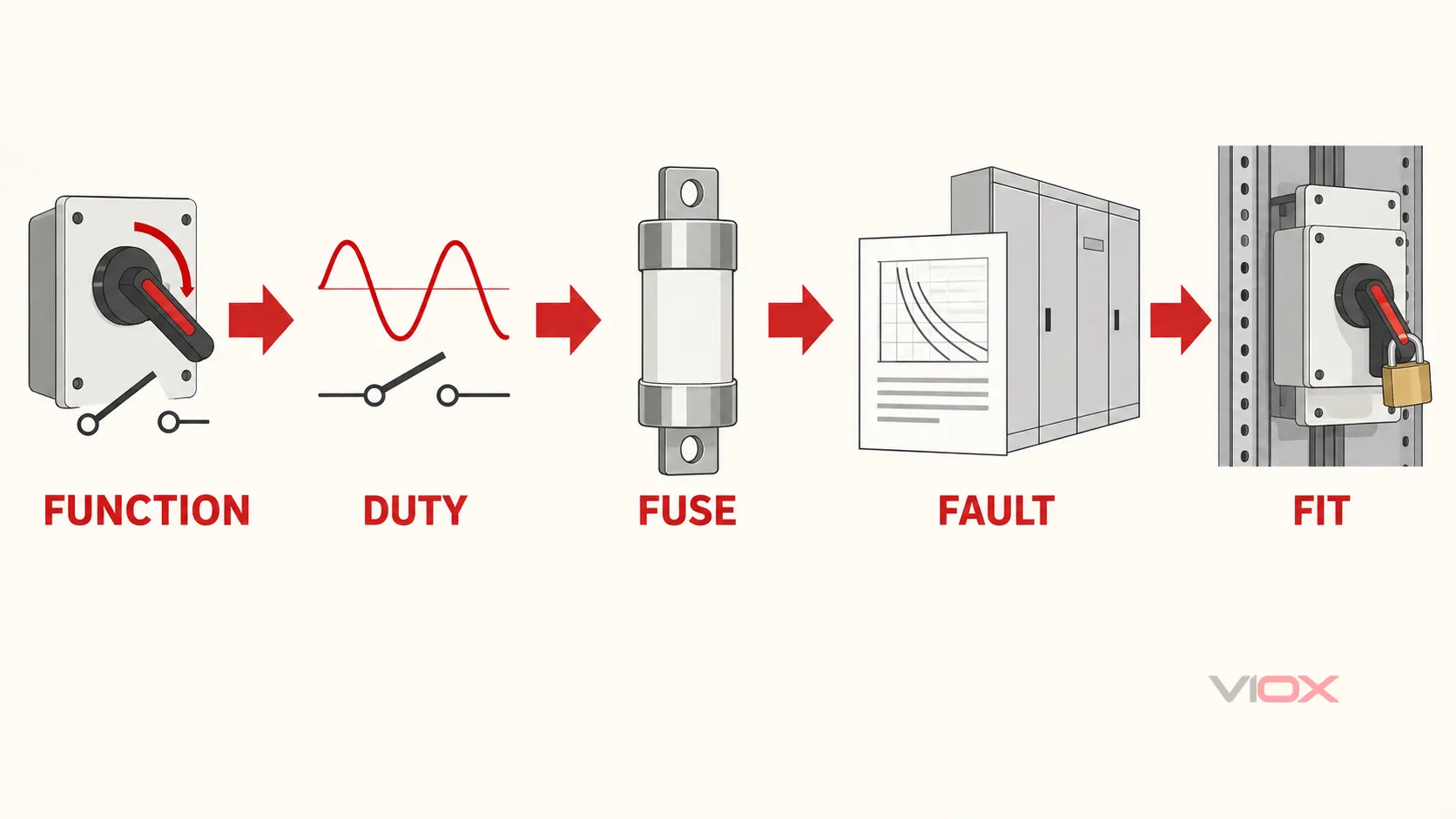
1. Define the Required Functions
State whether the device must:
- carry current continuously;
- make or break normal load current;
- isolate the circuit for maintenance;
- contain the required overcurrent-protective fuse links;
- operate all poles together or individually;
- provide indication, auxiliary contacts, interlocking, or remote operation.
Do not specify “fuse switch” when the real requirement is “three-pole switch-disconnector with compatible fuse links and a declared duty for the stated load.”
2. Identify the Market and Product Framework
For an IEC project, request the exact IEC 60947-3 device function and declared utilization category. For a North American project, request the exact listing or certification category, applicable standard, fuse class, and equipment or assembly conditions.
These frameworks should not be blended into a generic “IEC/UL equivalent” statement. A product may have evidence for one market, both markets, or a specific configuration only.
3. Match Voltage, Current, Poles, and Load Type
Confirm rated operational voltage and current for the actual circuit, frequency where relevant, number of switched poles, neutral arrangement, ambient/enclosure conditions, and load characteristic. Motors, resistive loads, distribution feeders, capacitive loads, and DC circuits do not impose identical switching duties.
For DC service, require an explicit DC voltage rating and the permitted pole configuration. Do not infer DC suitability from an AC rating or from physical similarity. DC switching can depend on contact arrangement and series pole use defined by the manufacturer.
4. Verify the Switching Duty
The utilization category is part of the rating, not a decorative suffix. Confirm it at the required operational voltage and current and for the intended operating frequency. Do not assume that a device described as an isolator is suitable for routine load switching, or that the presence of fuses upgrades the switch mechanism.
If the project only requires off-load isolation, document how the load current is removed before operation. If the device must open normal load current, request the matching declared switching duty.
5. Specify the Fuse System
Define the fuse-link system and the protective task:
- physical format and size, such as NH or the specified cylindrical or regional fuse system;
- utilization category or fuse class;
- rated current and voltage;
- breaking capacity;
- time-current and let-through requirements where coordination matters;
- striker, indicator, or monitoring requirements;
- approved compatibility with the device and carrier.
For IEC fuse categories, NH sizes, and curve interpretation, use the IEC 60269 fuse selection guide. A matching footprint does not make two fuse links electrically interchangeable.
6. Separate Fuse Breaking Capacity From Assembly Short-Circuit Evidence
The fault study establishes the prospective short-circuit current at the installation point. Compare it with the documented performance of the selected fuse link and the complete device or assembly combination.
Do not state that the fuse switch disconnector has the fuse link’s breaking capacity unless the applicable product documentation supports that complete arrangement. In North American machinery, UL Solutions likewise treats the disconnecting means, overcurrent protective device, controller, overload protection, and their combination as distinct elements when determining short-circuit current rating.
7. Confirm Mechanical and Maintenance Integration
Check mounting orientation, terminal arrangement, conductor material and range, enclosure clearances, accessibility, touch protection, operating handle, lock provision, door interlock, fuse replacement state, indication, and required documentation.
The instructions must define the permitted operating and maintenance sequence. A load-break rating does not authorize fuse replacement while energized, and an interlocked enclosure does not replace the site’s isolation and verification procedure.
Common Fuse Switch Disconnector Configurations
The same functional family can appear in several physical forms:
- enclosed fused disconnects with an external handle;
- open-type switch-disconnectors installed inside switchboards or control panels;
- compact DIN-rail fuse-combination devices for supported fuse systems;
- horizontal panel-mounted NH fuse switch-disconnectors;
- vertical busbar-mounted NH fuse switch-disconnectors;
- AC or DC versions with application-specific ratings and pole arrangements.
Configuration changes the selection inputs. A vertical NH unit, for example, requires exact busbar centers, bar dimensions, fuse size, pole operation, terminal direction, and assembly verification. Those details belong to the dedicated NH vertical fuse switch disconnector selection guide, not to the generic terminology decision.
If the unresolved choice is whether local fuses are needed at all, use the separate fused versus non-fused disconnect guide. That page owns the protection-location decision; this page assumes that a fuse-combination device is under consideration.
Copy-Ready RFQ Checklist
Before requesting a quotation, provide:
- required device function: switch, disconnector, or switch-disconnector with fuses;
- applicable market standard or certification requirement;
- AC or DC system, rated voltage, frequency, and earthing/system context where relevant;
- design current, load type, and required utilization category or switching duty;
- number of poles and neutral arrangement;
- fuse system, size, class/category, voltage, current, and indication requirements;
- prospective short-circuit current and required combination/SCCR evidence;
- mounting, busbar or panel interface, terminal direction, and conductor details;
- enclosure, touch-protection, interlock, padlocking, and access requirements;
- auxiliary contact, fuse monitoring, or remote-operation requirements;
- exact model datasheet, dimensional drawing, instructions, and applicable conformity documents.
For the wider protection hierarchy, start with the electrical fuse types and selection guide. For general fuse and holder families, review the VIOX low-voltage fuse range. For busbar-mounted NH applications, the VIOX bar fuse switch disconnector product page provides the commercial route; final selection still requires confirmation against the exact model documentation and project conditions.
Technical Sources
- IEC 60947-3:2020 — switches, disconnectors, switch-disconnectors and fuse-combination units
- IEC 60617 — graphical symbols including fuse-switch, fuse-disconnector, and fuse switch-disconnector
- UL Solutions — machine supply circuit and disconnecting means
- UL Solutions — combination motor controller components and SCCR