VIOX Electric
Language

Month: July 2025

  • How to Test If a Circuit Breaker Is Bad: Multimeter Checks, Symptoms, and Failure Modes

    How to Test If a Circuit Breaker Is Bad: Multimeter Checks, Symptoms, and Failure Modes

    Quick Answer: How Do You Test If a Circuit Breaker Is Bad?

    To test if a circuit breaker is bad, first look for visible and operating symptoms: the breaker will not reset, feels hot, smells burnt, trips with normal load, has scorch marks, or leaves the circuit without power even when the handle is ON. A qualified person can then use a multimeter to check whether voltage is present at the breaker output when the breaker is ON and whether the breaker passes power correctly.

    The most important rule is this:

    Do not assume the breaker is bad just because it trips. A breaker may be doing its job because the circuit has an overload, short circuit, ground fault, arc fault, loose connection, or damaged appliance.

    If there is burning smell, buzzing, heat, melted plastic, visible arcing, water damage, or a main breaker problem, stop testing and call a licensed electrician.


    Safety First: What You Can and Cannot Test

    Circuit breaker testing can involve live voltage inside an electrical panel. That is hazardous. Homeowners can safely observe symptoms and reset a breaker once when conditions are normal, but they should not remove panel covers, touch busbars, probe live service equipment, or perform tests they are not trained to do.

    Situation Safe Action
    Breaker trips once after an obvious overload Turn off loads, reset once, reduce load
    Breaker trips repeatedly Stop resetting and diagnose the circuit
    Breaker feels hot or smells burnt Turn off if safe and call an electrician
    Panel has scorch marks or buzzing Do not touch; call an electrician
    Main breaker problem Call an electrician
    You need live voltage testing inside the panel Use a qualified person

    Never replace a breaker with a higher amp rating to stop nuisance tripping. The breaker protects the wire. Upsizing without verifying conductor size and circuit design can create a fire hazard.


    Bad Breaker Symptoms Checklist
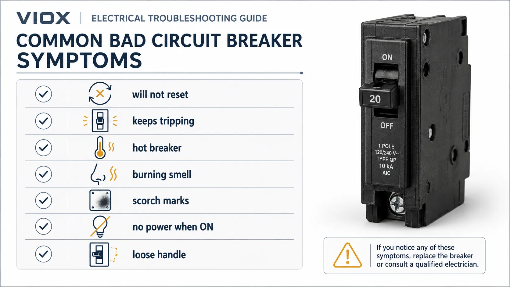
    Bad circuit breaker symptoms checklist including heat, burning smell, repeated tripping, and no power.
    Common bad circuit breaker symptoms including failure to reset, repeated tripping, overheating, burning smell, scorch marks, buzzing, and no power with the handle in the ON position.
    Symptom Possible Meaning What to Do
    Breaker will not reset Fault on circuit, damaged breaker, worn latch Turn off loads; do not force it
    Breaker trips immediately Short circuit, ground fault, arc fault, failed breaker Stop resetting and troubleshoot
    Breaker trips under normal load Weak breaker, overload, loose terminal, faulty appliance Compare load and circuit condition
    Breaker feels hot Loose connection, overload, poor contact, internal damage Call an electrician
    Burning smell Arcing, overheating, insulation damage Shut off power if safe
    Scorch marks or melted case Severe overheating or arcing Replace and inspect panel
    No power but handle is ON Failed internal contact, loose connection, circuit issue Voltage test by qualified person
    Handle feels loose or will not latch Mechanical wear or breaker damage Replace after diagnosis
    Breaker hums or buzzes Loose connection, overload, failing device Have panel inspected

    One symptom alone does not always prove the breaker is bad. A good diagnosis separates breaker failure from wiring and load problems.


    How to Test If a Circuit Breaker Is Bad With a Multimeter

    Live testing should be done only by a qualified person using a properly rated meter and safe electrical work procedures.

    In the field, a breaker diagnosis usually starts with a simple question: is the breaker failing to pass power, or is it correctly reacting to a fault downstream? That difference matters. Replacing a breaker that is correctly tripping from a short, ground fault, or overloaded appliance only resets the clock on the real problem.

    1. Confirm the Breaker Is Fully ON

    Many breakers trip to a middle position. To reset correctly, the handle usually must be pushed fully OFF first, then back ON. If the handle will not latch or feels mechanically loose, the breaker may be damaged or the circuit may still have a fault.
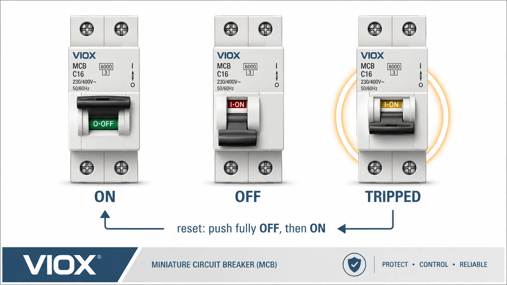
    Circuit breaker handle positions showing ON, OFF, and the tripped middle position.
    Circuit breaker handle positions showing that a tripped breaker often rests between ON and OFF and normally must be moved fully OFF before resetting to ON.

    2. Test Voltage at the Breaker Output
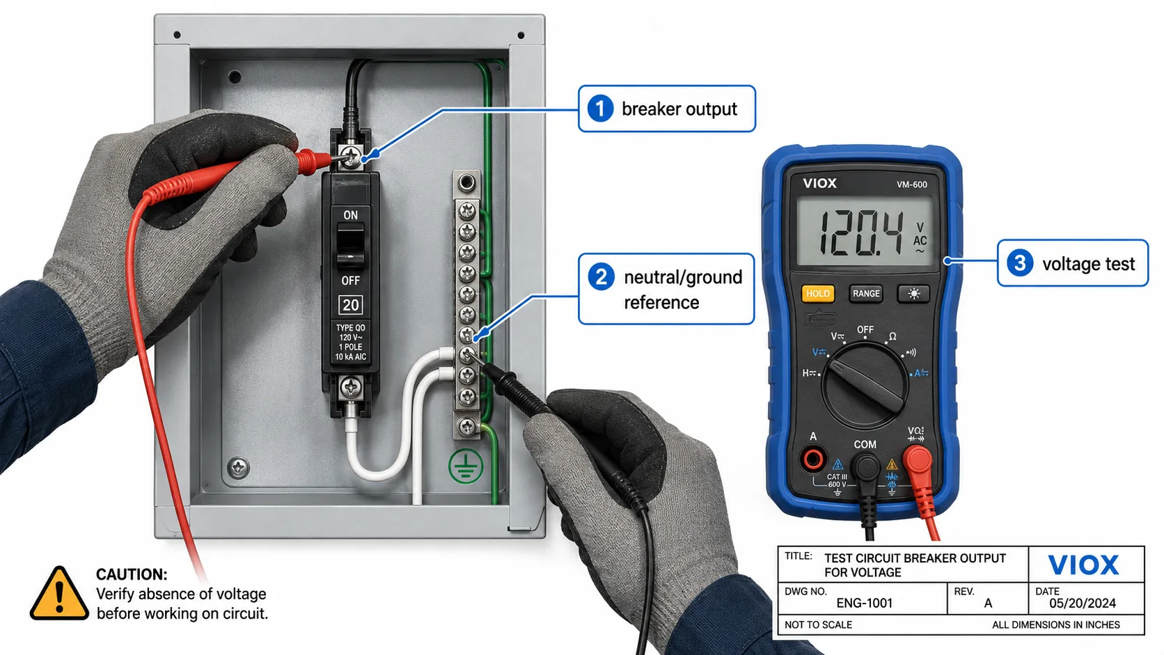
    Multimeter voltage test diagram for checking whether a circuit breaker passes power.
    Qualified-person voltage test showing how breaker output is checked to determine whether the breaker is passing power or the problem is downstream.

    With the breaker ON, a qualified person can measure voltage from the breaker load terminal to neutral or ground, depending on the circuit and system.

    Expected Result Possible Meaning
    Correct voltage at breaker output Breaker may be passing power; problem may be downstream
    No voltage at breaker output while breaker is ON Breaker may have failed internally or bus connection may be bad
    Unstable voltage Loose connection, damaged breaker, damaged conductor, or panel issue

    This test must be interpreted with the system type. A 120 V, 240 V, single-pole, double-pole, GFCI, AFCI, RCBO, or MCB circuit may require different test points.

    For documentation-heavy environments such as factories, machine panels, and data-center support rooms, technicians often record the panel ID, circuit number, measured voltage, connected load, and trip history before replacing a breaker. That record helps prevent the same circuit from being repaired twice for two different assumed causes.

    3. Test Continuity Only When De-Energized

    Continuity testing should only be done on a de-energized breaker that has been safely isolated. A continuity test can show whether the breaker contacts close when the handle is ON and open when OFF.

    Breaker Position Expected Continuity
    ON Continuity through the breaker
    OFF No continuity
    TRIPPED No continuity

    Do not use the continuity or resistance setting on a live circuit. That can damage the meter and create a serious shock or arc hazard.

    4. Understand the Limit of a Normal Multimeter

    A closed breaker should have very low contact resistance. However, accurate contact-resistance testing usually requires a low-resistance ohmmeter or micro-ohmmeter and a de-energized test setup.

    A normal handheld multimeter is not a reliable tool for judging subtle breaker contact wear. It may show near-zero resistance even when the breaker has heat-damaged contacts under load.


    How to Check a Breaker Without a Multimeter

    Without a multimeter, you can still check for warning signs, but you cannot prove the electrical condition of the breaker.

    Safe visual and operating checks include:

    • Does the breaker reset normally?
    • Does it trip again immediately?
    • Does the handle feel loose, gritty, or weak?
    • Is the breaker hot compared with neighboring breakers?
    • Is there a burning smell?
    • Are there scorch marks, discoloration, or melted plastic?
    • Does the problem happen only with one appliance?
    • Does the circuit lose power even when the breaker appears ON?

    These checks help decide whether to stop and call an electrician. They do not replace electrical testing.


    Can a Breaker Fail Without Tripping?

    Yes. A circuit breaker can fail without visibly tripping.

    Possible examples include:

    • internal contacts fail open, causing no power even when the handle is ON
    • contact surfaces become burned or pitted, causing heat under load
    • mechanical latch weakens and trips too easily
    • trip mechanism becomes unreliable
    • breaker-to-busbar contact becomes loose or overheated
    • terminal screw connection overheats

    The most dangerous failure is not always nuisance tripping. A breaker that cannot interrupt a fault correctly, overheats at the terminal, or makes poor busbar contact can create a fire or arc hazard.


    Bad Breaker vs Bad Circuit: How to Tell the Difference

    Situation More Likely Breaker More Likely Circuit or Load
    Trips only when one appliance starts Less likely Appliance inrush, overload, motor fault
    Trips with all loads unplugged Possible Hidden wiring fault also possible
    Breaker handle will not latch More likely Circuit fault may also prevent reset
    No power but breaker is ON Possible Loose wire or downstream fault also possible
    Breaker is visibly burned Very likely breaker/panel issue Circuit may have caused overheating
    New correct breaker also trips Less likely Circuit or load problem
    Original breaker feels loose on busbar Breaker or panel issue Not a load problem

    Replacing a breaker without diagnosing the circuit can hide the real problem. If the new breaker trips, the old breaker may not have been the cause.


    Circuit Breaker Failure Modes

    Circuit breakers can fail electrically, mechanically, or thermally.

    Failure Mode What Happens Common Clue
    Worn spring mechanism Breaker becomes weak or inconsistent Nuisance trips or loose handle
    Burned contacts Contacts overheat or fail to carry load cleanly Heat, smell, voltage drop
    Pitted contacts Repeated switching or fault stress damages surface Heat under load
    Loose terminal Conductor connection overheats Discoloration, buzzing, melted insulation
    Busbar clip damage Breaker does not grip panel bus correctly Heat at breaker back, unstable power
    Thermal element aging Thermal trip behavior changes Trips at lower-than-expected load
    Magnetic trip failure Fault interruption behavior may be compromised Requires professional testing
    Case damage Insulation and mechanical integrity compromised Cracks, melting, burn marks

    Most field diagnosis starts with visible symptoms, voltage testing, load behavior, and thermal signs. Detailed trip testing is usually not practical for homeowners.


    Circuit Breaker Resistance and Contact Resistance

    Breaker resistance is usually discussed when technicians suspect that the breaker contacts are not carrying current cleanly. The concept is valid, but the test is often misunderstood.

    When a breaker is closed, its contact resistance should be very low. The problem is that a cheap or normal handheld multimeter cannot accurately measure very low contact resistance under real load conditions. It also cannot reproduce heat rise, contact pressure, or fault-clearing behavior.

    For professional maintenance, contact resistance may be evaluated with specialized low-resistance test equipment under controlled conditions. For residential or small commercial troubleshooting, heat, voltage drop, visible damage, nuisance tripping, and proper voltage testing are usually more practical indicators.

    In an industrial panel, a thermographic scan can also reveal a suspect breaker connection before a complete failure occurs. A hot breaker terminal does not automatically prove the breaker itself is bad; it may point to a loose conductor, damaged busbar contact, poor crimp, overloaded circuit, or internal contact wear. The useful clue is the temperature difference compared with similar breakers under similar load.


    Field Example: When the Breaker Was Not the First Cause

    A common maintenance trap is replacing the breaker first because it is the visible device that trips. In one workshop-style fault pattern, a small motor circuit trips intermittently after running for several minutes. The breaker feels warm, so the first assumption is a weak breaker. After checking the load, however, the real issue is a loose terminal causing heat at the breaker output. The breaker is reacting to a bad connection, not creating the fault by itself.
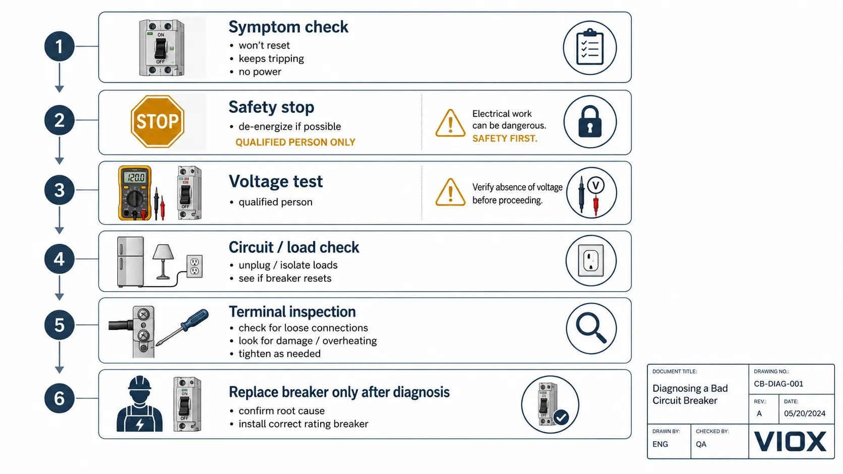
    Circuit breaker diagnostic flowchart for symptoms, multimeter testing, circuit faults, and replacement decisions.
    Circuit breaker diagnostic workflow separating visible symptoms, safe voltage tests, circuit or load faults, loose connections, and conditions that justify replacement.

    This is why breaker diagnosis should follow a sequence:

    1. Check visible damage and heat.
    2. Confirm the load and trip pattern.
    3. Test voltage safely.
    4. Inspect terminals and conductor condition.
    5. Only then decide whether the breaker should be replaced.

    Skipping directly to replacement can leave the dangerous connection in place.


    Weak Breaker Symptoms

    A weak breaker is a breaker that trips too easily, fails to latch reliably, or no longer behaves consistently under normal conditions.

    Common weak breaker symptoms include:

    • trips with a load that previously worked normally
    • handle feels loose or soft
    • trips more often after warming up
    • resets temporarily but trips again without a clear overload
    • neighboring similar circuits work normally under comparable load
    • breaker has a history of repeated trips or overheating

    Even then, confirm the circuit condition. Motors, compressors, heaters, and power tools may draw high inrush current that looks like a weak breaker problem.


    How Electricians Load Test a Circuit Breaker

    A load test checks how the breaker and circuit behave under controlled current. This is not the same as randomly plugging in appliances until the breaker trips.

    An electrician may review:

    • actual circuit load
    • conductor size
    • breaker rating
    • terminal condition
    • voltage drop
    • temperature rise
    • trip history
    • load type and inrush current
    • panel condition

    For molded case circuit breakers, industrial breakers, or critical equipment, professional testing may include insulation testing, contact resistance testing, primary injection testing, or manufacturer-specific maintenance procedures.


    When to Replace a Circuit Breaker

    Replacement is usually justified when:

    • breaker is physically damaged
    • breaker has scorch marks or melting
    • breaker will not reset after circuit faults are cleared
    • breaker overheats at normal load
    • breaker has failed voltage or continuity testing
    • breaker trips inconsistently after the circuit is verified
    • breaker does not fit tightly in the panel
    • breaker is obsolete, recalled, or not approved for the panel

    The replacement breaker must match the panel and circuit requirements. Same amperage alone is not enough. Check brand compatibility, breaker series, voltage, pole count, interrupting rating, wire size, and panel labeling.


    When to Call an Electrician Immediately

    Call an electrician immediately if you notice:

    • burning smell
    • smoke
    • buzzing or crackling from the panel
    • melted breaker or wire insulation
    • scorch marks
    • hot panel cover
    • main breaker issue
    • water near the panel
    • breaker repeatedly trips after reset
    • lights flicker across multiple circuits
    • breaker feels loose on the busbar

    These signs can indicate arcing, overheating, loose connections, or panel damage.


    FAQ

    How do I know if a breaker is bad?

    A breaker may be bad if it will not reset, trips under normal load after the circuit is verified, feels hot, smells burnt, has scorch marks, or does not pass voltage when ON. However, many breaker trips are caused by circuit or load problems, not a bad breaker.

    How do you test if a circuit breaker is bad with a multimeter?

    A qualified person can test voltage at the breaker output when the breaker is ON. Continuity testing can be done only when the breaker is de-energized and isolated. Do not use resistance or continuity mode on a live circuit.

    Can a breaker fail without tripping?

    Yes. A breaker can fail open, overheat internally, develop poor contact, loosen on the busbar, or fail to carry load properly without showing a normal trip position.

    Can I test a circuit breaker without a multimeter?

    You can check symptoms such as heat, smell, visible damage, loose handle, repeated trips, or failure to reset. But without a meter or professional testing, you cannot confirm the electrical condition of the breaker.

    What are weak breaker symptoms?

    Weak breaker symptoms include nuisance tripping, loose handle feel, failure to latch, tripping under normal load, and inconsistent behavior after the circuit and load have been verified.

    What is circuit breaker contact resistance?

    Contact resistance is the resistance across the breaker contacts when closed. It should be very low, but accurate measurement requires proper low-resistance test equipment. A normal multimeter is not reliable for detailed breaker contact diagnosis.

    Should I replace a breaker that keeps tripping?

    Not immediately. First identify whether the trip is caused by overload, short circuit, ground fault, arc fault, loose wiring, or appliance failure. Replace the breaker only after the circuit condition is checked.

    Can I replace a breaker with a higher amp breaker?

    No. A higher amp breaker can overload the wire and create a fire hazard unless the entire circuit is designed and approved for that rating.


    Conclusion

    The best way to test if a circuit breaker is bad is to combine symptom checks, safe electrical testing, and circuit diagnosis. A bad breaker can cause no power, overheating, nuisance trips, weak reset action, or visible damage. But a breaker that trips repeatedly may also be responding correctly to an unsafe circuit condition.

    If the issue involves heat, burning smell, scorch marks, repeated trips, main breaker problems, or live panel testing, stop guessing and call a qualified electrician. The goal is not just to replace a breaker. The goal is to find whether the real problem is the breaker, the load, the wiring, or the panel connection.

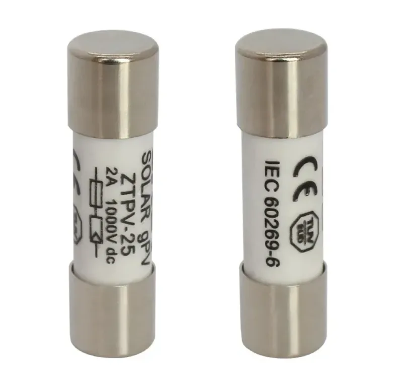
  • How to Test a Bad DC Fuse in PV System

    How to Test a Bad DC Fuse in PV System

    When your PV system suddenly stops producing power or shows reduced output, a blown DC fuse might be the culprit. Learning how to test DC fuse solar system components can save you time, money, and prevent potential safety hazards. This comprehensive guide walks you through the entire process of identifying, testing, and troubleshooting bad DC fuses in your solar installation.

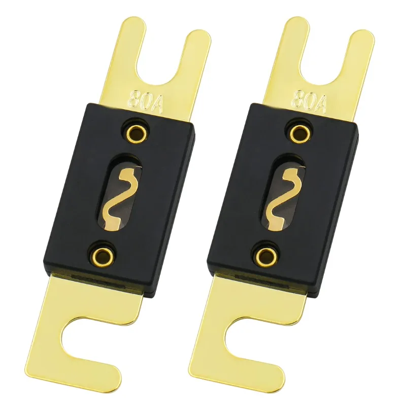
    two DC fuse

    Signs Your Solar DC Fuse May Be Bad

    Before diving into testing procedures, it’s crucial to recognize the warning signs that indicate a potential fuse failure in your solar system. Blown solar fuse symptoms often manifest in several distinct ways that can help you pinpoint the problem quickly.

    The most obvious indicator is a sudden complete loss of power generation from your solar array. If your monitoring system shows zero watts being produced on a sunny day, or your batteries aren’t charging despite optimal conditions, a blown fuse could be interrupting the electrical pathway.

    You might also notice inconsistent solar output where some panels or strings produce power while others don’t. This typically occurs in systems with multiple fuse protection points, such as combiner boxes with individual string fuses.

    Physical signs include a burnt smell around electrical connections, visible discoloration on fuse holders, or obvious damage to the fuse element itself. Some fuses have clear housings that allow you to visually inspect the internal wire element for breaks or burn marks.

    System error messages from your inverter or charge controller can also indicate fuse problems. Many modern solar components display specific fault codes when they detect open circuits or unexpected voltage conditions that could result from blown fuses.

    Essential Tools for Testing Solar DC Fuses

    Proper solar fuse testing requires specific tools to ensure accurate readings and maintain safety throughout the process. A digital multimeter is your primary diagnostic tool, but make sure it has adequate current capacity for your system’s specifications.

    Your multimeter should have a fuse rating greater than the short circuit current of your solar panels. For example, if your panels have a short circuit current of 9 amps, ensure your multimeter has at least a 10-amp fuse capacity to prevent damage during testing.

    Essential safety equipment includes insulated gloves rated for electrical work, safety glasses to protect against potential sparks or debris, and non-conductive tools to prevent accidental short circuits. These items aren’t optional—they’re critical for your safety when working with DC electrical systems.

    Additional helpful tools include a DC clamp meter for non-intrusive current measurements, spare fuses with the correct amperage ratings for immediate replacement, and a flashlight or headlamp for clear visibility in dimly lit electrical enclosures.

    Keep a notebook or smartphone handy to document voltage readings, fuse ratings, and any observations that might help with troubleshooting or future maintenance.

    Safety Precautions Before Testing Solar Fuses

    DC fuse troubleshooting solar systems requires strict adherence to safety protocols due to the unique characteristics of photovoltaic electrical systems. Unlike AC circuits, solar panels continuously generate electricity whenever exposed to light, making complete power isolation more challenging.

    Always begin by turning off all system components in the proper sequence. Start with the AC disconnect at your electrical panel, then the DC disconnect at your inverter, and finally any battery disconnects if you have energy storage. This multi-step shutdown process ensures all potential power sources are isolated.

    Remove the fuse from the circuit whenever possible for the most accurate testing results. Testing in-circuit can sometimes provide misleading readings due to parallel paths or component interactions within your solar system.

    Work only in dry conditions and never attempt electrical work during rain, snow, or high humidity. Moisture can create dangerous conditions and affect the accuracy of your measurements.

    Remember that even with system components turned off, solar panels still generate voltage when exposed to light. Cover panels with opaque material or work during low-light conditions when possible to minimize this residual voltage.

    Step-by-Step Guide: How to Test DC Fuse Solar System Components

    Method 1: Testing Removed Fuses (Continuity Test)

    The continuity test provides the most reliable method for testing bad DC fuse components because it eliminates interference from other system elements. This approach works best when you can safely remove the fuse from its holder.

    Begin by powering down your entire solar system using the shutdown procedure outlined above. Wait several minutes after shutdown to allow any residual energy in system capacitors to dissipate safely.

    Carefully remove the suspected fuse from its holder, noting its orientation and any identifying markings. Many fuses have directional indicators or specific positioning requirements for proper operation.

    Set your multimeter to continuity mode, typically indicated by a diode symbol or sound wave icon. Test your multimeter’s functionality by touching the probe tips together—you should hear a clear beep indicating the continuity function is working properly.

    Place one probe on each end of the fuse, ensuring good contact with the metal terminals. The order doesn’t matter for this test since fuses are non-polarized devices.

    A functioning fuse will produce an immediate beep from your multimeter, indicating a complete electrical path through the fuse element. No beep means the fuse element has melted or broken, confirming the fuse is blown and needs replacement.

    Method 2: Testing Fuses In-Circuit (Voltage Test)

    When removing a fuse isn’t practical or safe, you can test it while installed using the voltage measurement method. This technique is particularly useful for fuses in difficult-to-access locations or when you want to avoid disrupting system operation.

    Keep your solar system in its normal operating state for this test, but ensure you’re wearing appropriate safety equipment and taking proper precautions around live electrical circuits.

    Set your multimeter to measure DC voltage with a range higher than your system’s operating voltage. Most residential solar systems operate at 400-600 volts DC, so select an appropriate range on your meter.

    Carefully place the multimeter probes on each side of the fuse terminals. You’re measuring the voltage drop across the fuse under normal operating conditions.

    A good fuse will show little to no voltage drop, typically less than 0.1 volts. This minimal reading indicates current is flowing freely through the fuse element with normal resistance.

    If you measure a significant voltage across the fuse—especially if it’s close to your system’s full operating voltage—this indicates the fuse is blown and blocking current flow.

    Method 3: Resistance Testing for Confirmation

    Resistance testing provides additional confirmation of fuse condition and can help identify fuses that are beginning to fail but haven’t completely blown yet.

    Remove the fuse from the circuit and set your multimeter to measure resistance, typically indicated by the omega (Ω) symbol. Select the lowest resistance range for the most sensitive readings.

    Touch the meter probes to the fuse terminals, ensuring clean contact points for accurate measurements. Oxidation or corrosion on terminals can affect readings, so clean connections if necessary.

    A healthy fuse should show near-zero resistance, typically less than 0.1 ohms. This low resistance confirms the fuse element provides an unobstructed path for electrical current.

    High resistance readings or infinite resistance (often displayed as “OL” for overload) indicate fuse failure. Some fuses may show gradually increasing resistance as they age, providing an early warning of impending failure.

    Understanding DC Fuse Types in Solar Systems

    Different locations within your solar system require specific fuse types designed for their unique electrical characteristics and environmental conditions. Understanding these differences helps ensure proper testing procedures and replacement selections.

    ANL fuses are commonly used for high-current applications like the connection between charge controllers and battery banks. These cylindrical fuses typically handle 30-400 amps and use bolt-on connections for secure mounting in marine-grade fuse holders.

    Anl fuse

    MEGA fuses serve similar high-current applications but use a different physical form factor. They’re often found in automotive-style applications and fit into specialized fuse blocks designed for easy replacement.

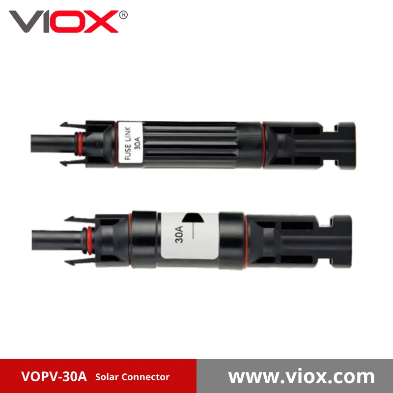
    MC4 inline fuses provide panel-level protection in systems with parallel-connected solar panels. These weatherproof fuses integrate directly into the MC4 connector system, making them ideal for outdoor installations where individual panel protection is required.

    VIOX VOPV-30A(1000V)-Fuse Solar Connector

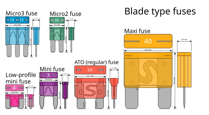
    Blade fuses protect smaller DC loads within your system, such as monitoring equipment, fans, or control circuits. These familiar automotive-style fuses are easy to test and replace but aren’t suitable for high-current solar applications.

    Blade fuses

    Common Causes of Solar DC Fuse Failure

    Understanding why fuses fail helps prevent future problems and guides your troubleshooting efforts when testing DC fuses in solar systems. Most fuse failures result from electrical faults rather than normal wear, making root cause analysis essential.

    Overcurrent conditions represent the most common cause of fuse failure. These can result from ground faults in your wiring, short circuits within system components, or backfeed currents from improperly configured parallel strings.

    Poor electrical connections generate excessive heat that can cause fuse failure even when current levels are within normal limits. Loose terminal screws, corroded connections, or improperly crimped wire connections create high-resistance joints that generate damaging heat buildup.

    Using incorrect fuse ratings for your application almost guarantees premature failure. Fuses sized too low for the circuit will blow unnecessarily, while oversized fuses won’t provide adequate protection and may allow dangerous overcurrent conditions to damage other system components.

    Environmental factors like moisture infiltration, extreme temperatures, or UV exposure can degrade fuse components over time. This is particularly problematic for fuses installed in outdoor locations without proper weatherproof enclosures.

    Troubleshooting After Finding a Bad Fuse

    Discovering a blown fuse is just the beginning of your diagnostic process. Simply replacing the fuse without identifying the underlying cause will likely result in repeated failures and potential safety hazards.

    Start your root cause analysis by carefully inspecting all electrical connections in the affected circuit. Look for signs of overheating such as discolored wires, melted insulation, or burnt terminals. Tighten any loose connections and clean corroded terminals before proceeding.

    Examine the wiring for physical damage that could cause short circuits or ground faults. Rodent damage, abrasion from sharp edges, or degradation from UV exposure can create fault conditions that repeatedly blow fuses.

    Verify that the blown fuse was properly sized for its application. Solar DC fuses should typically be rated at 1.25 to 1.56 times the short circuit current of the protected circuit. Using the manufacturer’s specifications ensures optimal protection without nuisance trips.

    Test other system components that could cause overcurrent conditions. This includes checking solar panels for internal faults, testing charge controllers for proper operation, and verifying inverter functionality.

    When to Call a Professional vs DIY Testing

    While many solar fuse testing procedures are within the capabilities of informed DIY enthusiasts, certain conditions require professional intervention for safety and effectiveness.

    High-voltage systems operating above 50 volts DC present increased safety risks that require specialized training and equipment. These systems can deliver dangerous or lethal shocks, making professional assessment the safer choice.

    Repeated fuse failures often indicate complex system problems that require advanced diagnostic skills and specialized equipment. Professional solar technicians have experience with these challenging scenarios and access to tools like thermal imaging cameras and advanced electrical analyzers.

    Fire damage or evidence of significant overheating demands immediate professional attention. These conditions can indicate serious safety hazards that require expert evaluation to prevent equipment damage or personal injury.

    If you’re uncomfortable working with electrical systems or lack confidence in your troubleshooting abilities, professional assistance provides peace of mind and ensures proper system operation.

    Preventing Future Solar Fuse Problems

    Proactive maintenance significantly reduces the likelihood of fuse failures and extends the overall lifespan of your solar system. Regular solar fuse testing as part of a comprehensive maintenance program identifies potential problems before they cause system failures.

    Schedule visual inspections of all electrical connections at least twice yearly, checking for signs of corrosion, looseness, or overheating. Clean and tighten connections as needed, using appropriate torque specifications from manufacturer documentation.

    Monitor your system’s performance data for trends that might indicate developing problems. Gradually declining output from specific strings or irregular current patterns can provide early warning of conditions that might lead to fuse failures.

    Ensure all electrical enclosures have proper weatherproofing to prevent moisture infiltration. Replace damaged gaskets, seal cable entries, and verify that enclosure covers are properly secured.

    Keep spare fuses with the correct ratings readily available for quick replacement when needed. This minimizes system downtime and prevents the temptation to use incorrect fuse ratings as temporary solutions.

    Advanced Testing Techniques

    DC clamp meters provide valuable diagnostic capabilities for advanced solar fuse testing, especially in systems with multiple parallel strings where current imbalances might indicate developing problems.

    These instruments measure current flow without breaking circuit connections, allowing you to monitor individual string currents during normal system operation. Significant variations between similar strings can indicate panel problems, wiring issues, or impending fuse failures.

    When testing string fuses in combiner boxes, compare current readings from each protected circuit. Strings with identical panels and wiring should produce very similar current levels under the same irradiance conditions.

    Use thermal imaging if available to identify hot spots in electrical connections that might not be visible during normal inspections. Elevated temperatures often precede fuse failures and other electrical problems.

    Solar Fuse Testing FAQs

    Can I test a fuse without removing it from the circuit?
    Yes, using the voltage measurement method described above. However, removing the fuse provides more accurate results and eliminates potential interference from parallel circuit paths.

    What multimeter settings should I use for solar fuse testing?
    Use continuity mode for removed fuses, DC voltage mode for in-circuit testing, and resistance mode for additional confirmation. Ensure your meter’s voltage and current ratings exceed your system’s specifications.

    How do I know if my multimeter’s internal fuse is blown?
    If your multimeter won’t measure current or shows inconsistent readings, test its internal fuse using another meter or by checking continuity across the fuse with the meter disassembled.

    What’s the difference between fast and slow blow fuses in solar applications?
    Fast blow fuses respond immediately to overcurrent conditions, while slow blow fuses tolerate brief current surges. Solar applications typically use slow blow fuses to handle normal startup currents and brief cloud-induced variations.

    By following these comprehensive testing procedures and understanding the principles behind DC fuse troubleshooting solar systems, you can maintain reliable operation of your photovoltaic installation while ensuring the safety of both equipment and personnel. Regular testing and proactive maintenance will help maximize your solar investment’s performance and longevity.

    Related

    AC Fuse vs DC Fuse: Complete Technical Guide for Safe Electrical Protection

    How Does a Fuse Holder Work?

  • 7 Critical Warning Signs Your Air Circuit Breaker Is Failing

    7 Critical Warning Signs Your Air Circuit Breaker Is Failing

    Air circuit breakers (ACBs) are the unsung heroes of industrial electrical systems, silently protecting equipment worth millions of dollars. But when these critical components begin to malfunction, the warning signs can be subtle—until they’re not. Understanding how to identify air circuit breaker malfunction signs early can save your facility from catastrophic failures, costly downtime, and safety hazards.

    Air Circuit Breakers are the cause of almost 20% of power distribution system failures. This is mainly due to a lack of maintenance, dust, hardened grease, corrosion or frozen parts that prevent the proper operation of the trip linkage. The key is knowing what to look for before minor issues become major problems.

    What Makes Air Circuit Breaker Malfunction Detection So Critical?

    Air Circuit Breakers01

    Air circuit breakers operate in demanding industrial environments where they’re exposed to dust, temperature fluctuations, mechanical stress, and electrical loads that can gradually degrade their performance. ACBs maintain functioning and keep facilities safe by interrupting electrical current flow during fault conditions, but their protective capability depends entirely on their mechanical and electrical integrity.

    Unlike smaller residential breakers, industrial ACBs control circuits carrying hundreds or thousands of amperes. When they fail, the consequences extend far beyond a simple power outage—you’re looking at potential equipment damage, production shutdowns, and safety risks that can impact your entire operation.

    The 7 Most Critical Air Circuit Breaker Malfunction Signs

    1. Frequent or Unexplained Tripping

    The most obvious sign of air circuit breaker problems is frequent tripping without apparent cause. Non accident trip refers to tripping without short circuit and overload fault. If your ACB trips repeatedly under normal load conditions, this indicates internal component degradation.

    What to check:

    • Trip unit calibration and settings
    • Operating mechanism alignment
    • Contact wear and spring tension
    • Control circuit integrity

    Immediate action: Document tripping patterns and load conditions when trips occur. This data helps maintenance teams identify whether the problem lies with the breaker itself or external factors.

    2. Failure to Close or Stay Closed

    There are many reasons why the air circuit breaker can not be closed. An ACB that won’t close reliably or immediately opens after closing signals serious mechanical or electrical problems within the operating mechanism.

    Common underlying causes:

    • Energy storage spring failure: When closing, the four-link mechanism of the air circuit breaker can not push to the dead point and the mechanism can not self-maintain in the closing position.
    • Stuck operating mechanism: Foreign debris or lack of lubrication in moving parts
    • Undervoltage release issues: Too low voltage or power failure of the undervoltage release coil will also trip the air circuit breaker and cannot reclose.
    • Worn trip mechanism components

    3. Visible Physical Damage and Overheating Signs

    Physical inspection often reveals the most telling air circuit breaker malfunction signs. Look for these critical warning indicators:

    Overheating symptoms:

    • Discoloration around terminals and connections
    • Scorch marks signal overheating, posing a serious fire risk.
    • Burnt or melted insulation materials
    • Unusual heat generation during normal operation

    Mechanical damage indicators:

    • Cracked or damaged arc chutes
    • Corroded or pitted contacts
    • Loose mounting hardware
    • Oil or grease leakage from operating mechanisms

    4. Abnormal Sounds During Operation

    Your ears can detect air circuit breaker problems before visual inspection reveals them. Normal ACB operation produces consistent, predictable sounds during opening and closing cycles.

    Warning sounds to investigate:

    • Grinding or scraping noises during operation
    • Unusual clicking or chattering
    • Humming or buzzing from the control circuits
    • Silence when the breaker should be operating

    Buzzing noises indicate wiring problems or overloads that need immediate attention. Buzzing noises can also suggest issues with the trip coil, loose terminal connections, or faulty stationary contacts within the circuit breaker.

    5. Control Circuit and Auxiliary Contact Problems

    Modern ACBs rely heavily on control circuits for remote operation and status indication. Malfunctioning control circuits often provide early warning of broader air circuit breaker issues.

    Control circuit warning signs:

    • Inconsistent position indication
    • Remote operation commands not executing
    • Auxiliary contacts providing incorrect status signals
    • Control power consumption outside normal parameters

    Investigation priorities:

    • Poor contacts such as closing buttons, relay contacts, auxiliary contacts of circuit breakers, etc., and damaged components may lead to circuit blockage and power failure of trip coils.
    • Verify control voltage levels and stability
    • Test auxiliary contact operation and alignment

    6. Contact Degradation and Arc Chute Issues

    The primary contacts and arc chutes bear the brunt of electrical stress during normal operation and fault interruption. Their condition directly impacts ACB reliability and safety.

    Contact condition assessment:

    • If the thickness of silver alloy contact layer on the main contacts (dynamic and static contacts) is less than 1mm due to electric wear, it must be replaced
    • Contact alignment and spring pressure verification
    • Surface condition and pitting evaluation

    Arc chute inspection points:

    • The arc chutes must then be inspected for any dirt or moisture. There may be some black coloration on the arc chutes’ fins, which is normal and acceptable as long as they are not damaged.
    • Proper positioning and mounting
    • Deion plate condition and cleanliness

    7. Insulation Degradation

    The insulation performance of air circuit breaker will gradually deteriorate after long-term use. If improper maintenance is carried out in ordinary times, dust accumulation on the surface of insulating parts and moisture erosion will accelerate insulation aging, which may cause short circuit between phases or relative ground.

    Insulation assessment methods:

    • Visual inspection for contamination and damage
    • Insulation resistance testing
    • Dielectric strength verification
    • Environmental factor evaluation (humidity, temperature, contamination)

    When to Take Immediate Action

    Certain air circuit breaker malfunction signs require immediate attention to prevent safety hazards or equipment damage:

    Emergency situations requiring immediate shutdown:

    • Any visible arcing or sparking
    • Smoke or burning odors
    • A circuit breaker that is hot to the touch is a significant red flag.
    • Complete failure to operate when commanded
    • Evidence of internal component failure

    Urgent but not emergency conditions:

    • Frequent nuisance tripping
    • Inconsistent operation timing
    • Minor control circuit issues
    • Early-stage contact wear

    Preventive Maintenance: Your First Line of Defense

    The most effective approach to air circuit breaker malfunction prevention combines regular inspection schedules with condition-based monitoring. High-voltage circuit breakers should be inspected every six to 12 months, while medium-voltage circuit breakers should undergo maintenance annually or after every 2,000 operations.

    Essential maintenance activities:

    • Contact inspection and maintenance: After each short-circuit current cut-off, the air circuit breaker shall be checked as follows: (1) Smoke marks on the main and arc contacts are wiped off with alcohol. (2) If small metal particles form on the contact surface, they should be cleaned and smoothed.
    • Operating mechanism lubrication and adjustment
    • Control circuit testing and calibration
    • Insulation cleaning and testing
    • Trip unit functional verification

    Advanced Diagnostic Techniques

    Modern facilities increasingly rely on predictive maintenance technologies to detect air circuit breaker problems before they cause failures:

    Condition monitoring tools:

    • Thermal imaging, also known as infrared thermography, is a non-destructive testing method to detect electrical device anomalies.
    • Vibration analysis for mechanical component assessment
    • Contact resistance measurement
    • Partial discharge testing for insulation evaluation

    The Cost of Ignoring Warning Signs

    Delaying action when air circuit breaker malfunction signs appear can have severe consequences. In real-world scenarios, the consequences of ignoring these signs can be severe. For instance, an air compressor at a metal processing facility experienced a fire caused by control damage, resulting in a comprehensive revamp of the power infrastructure.

    Financial impact considerations:

    • Emergency repair costs vs. planned maintenance expenses
    • Production downtime and lost revenue
    • Secondary equipment damage from electrical faults
    • Safety incident costs and regulatory implications

    Building a Proactive ACB Management Program

    Creating an effective air circuit breaker reliability program requires structured approach combining regular inspections, condition monitoring, and maintenance planning:

    Program components:

    • Baseline assessment of all ACBs in your facility
    • Risk-based maintenance scheduling based on criticality and condition
    • Training programs for operations and maintenance staff
    • Documentation systems for tracking performance and maintenance history
    • Emergency response procedures for ACB failures

    Conclusion: Early Detection Saves Everything

    Recognizing air circuit breaker malfunction signs early protects your facility from the cascading effects of electrical system failures. The seven warning signs outlined here—frequent tripping, closing failures, physical damage, abnormal sounds, control circuit issues, contact degradation, and insulation problems—provide a comprehensive framework for ACB condition assessment.

    Remember that air circuit breaker problems rarely occur suddenly. They develop gradually, giving you opportunities to identify and address issues before they become critical. Regular inspection, proper maintenance, and prompt response to warning signs ensure your ACBs continue protecting your electrical systems reliably.

    Key takeaways for facility managers:

    • Implement systematic ACB inspection procedures
    • Train staff to recognize early warning signs
    • Establish clear escalation procedures for different types of problems
    • Invest in condition monitoring technology for critical applications
    • Maintain detailed records of ACB performance and maintenance activities

    By staying vigilant for these air circuit breaker malfunction signs and taking prompt corrective action, you’re not just maintaining equipment—you’re protecting your entire operation from potentially catastrophic electrical failures.

    Related

    Complete Guide to Air Circuit Breakers (ACB)

  • Complete Guide to Air Circuit Breakers (ACB): Working Principle, Types, Installation & Maintenance

    Complete Guide to Air Circuit Breakers (ACB): Working Principle, Types, Installation & Maintenance

    What Is an Air Circuit Breaker (ACB)?

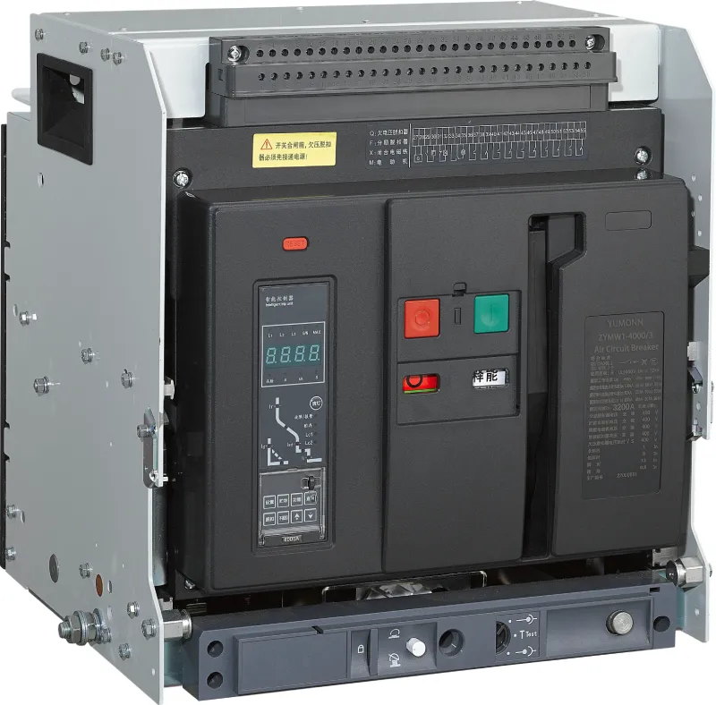
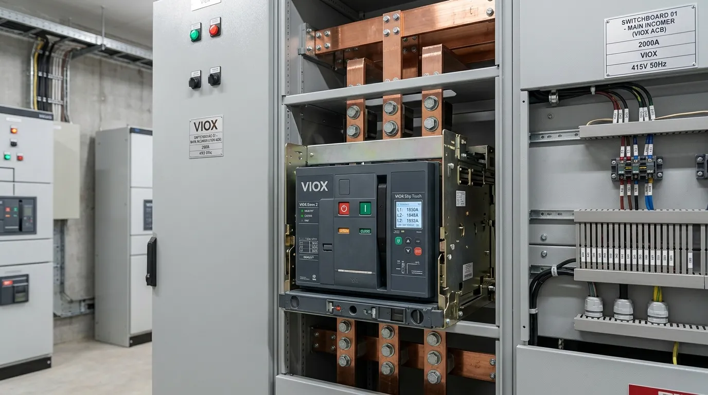
    Air circuit breaker installed in a low-voltage main switchboard
    Air circuit breaker installed in a low-voltage main switchboard, demonstrating its robust construction for high-capacity power distribution.

    An air circuit breaker is a low-voltage circuit breaker designed to protect high-current power distribution systems against overloads, short circuits, and other electrical faults. Commonly shortened to ACB, this type of circuit breaker uses air at atmospheric pressure as its arc-extinguishing medium — the mechanism that safely interrupts the electrical arc formed when the breaker opens under fault or load conditions. Because of their high current capacity, adjustable protection settings, and robust construction, air circuit breakers are the standard choice for main distribution boards, switchboards, motor control centers, and other high-capacity installations in commercial and industrial electrical systems.

    Quick Reference: ACB at a Glance

    Parameter Specification
    Voltage Rating Low voltage (typically up to 690 V AC per IEC 60947-2)
    Current Range Commonly 630 A to 6300 A (varies by manufacturer)
    Typical Role Main incomer, bus coupler, generator breaker
    Construction Type Fixed or draw-out
    Trip Unit Electronic (microprocessor-based) with adjustable LSI/LSIG protection
    Arc Medium Air at atmospheric pressure
    Primary Standard IEC 60947-2 (or regional equivalent)

    ACB vs MCCB vs VCB: Quick Comparison

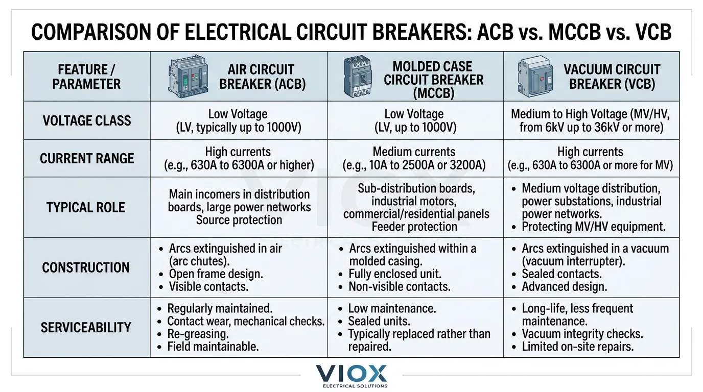
    Comparison infographic showing the differences between ACB, MCCB, and VCB
    Comparison infographic detailing the key technical parameters, roles, and structural differences between Air Circuit Breakers (ACB), Molded Case Circuit Breakers (MCCB), and Vacuum Circuit Breakers (VCB).

    Understanding where air circuit breakers fit in the protection hierarchy requires comparing them to related breaker types. The table below shows how ACBs differ from molded case circuit breakers and vacuum circuit breakers:

    Feature ACB MCCB VCB
    Voltage Class Low voltage (≤690 V) Low voltage (≤690 V) Medium voltage (3.3–36 kV)
    Current Range 630–6300 A 16–2500 A 630–4000 A
    Typical Role Main distribution protection Feeder protection Medium-voltage switching
    Trip Unit Electronic, adjustable Thermal-magnetic or electronic Relay-based
    Construction Fixed or draw-out Fixed (bolt-on/plug-in) Fixed or withdrawable
    Arc Medium Air Air Vacuum
    Serviceability Field-maintainable Sealed, limited service Sealed vacuum bottles

    An ACB typically serves at the main switchboard level as an incomer or bus coupler, while MCCBs protect downstream feeders and distribution circuits. VCBs operate in a different voltage class entirely — medium voltage — and sit upstream of the distribution transformer.

    In practical terms, an ACB is selected when the system current exceeds what smaller branch-circuit devices can handle, when the protection settings need to be precisely adjustable for coordination purposes, or when the installation demands a breaker that can be inspected, tested, and maintained without replacing the entire device. This is why air circuit breakers are commonly discussed alongside MCCBs rather than MCBs — ACBs sit at the top of the low-voltage protection hierarchy, where current levels are highest and coordination requirements are most demanding.

    Low-voltage ACB selection and performance are typically discussed within the framework of IEC 60947-2 or the applicable regional equivalent (UL 1066 in North America, GB 14048.2 in China). If you are looking for the acronym-only explanation, ACB Full Form in Electrical is the shorter companion page.

    What an ACB Is

    An air circuit breaker is a protective switching device engineered for low-voltage power systems where high current capacity, adjustable electrical fault protection, and long-term maintainability matter simultaneously. Understanding what sets an ACB apart requires looking beyond the arc-extinguishing medium — the differences are structural, functional, and operational.

    An ACB typically offers higher frame sizes and rated currents than other low-voltage breaker families. Where an MCCB might reach 1600 A to 2500 A depending on the manufacturer, air circuit breakers commonly cover 630 A to 6300 A, with some industrial models extending higher. This current capacity is essential for main switchboard applications where the entire building or facility load flows through a single device.

    The electronic trip unit in a modern ACB is a microprocessor-based controller that can be programmed with adjustable pickup levels, time delays, and coordination curves across multiple protection zones — long-time, short-time, instantaneous, and ground fault. This adjustability allows the ACB to coordinate properly with downstream MCCBs and upstream utility protection devices, ensuring selective fault clearing rather than system-wide tripping.

    Air circuit breakers are designed to integrate into switchboards as the central protective device, with standardized cradle systems, interlocking mechanisms, and communication interfaces. Most ACB families are available in both fixed and draw-out configurations, giving engineers flexibility to match installation style to maintenance requirements — a choice that only arises with ACBs, not smaller circuit breakers.

    Where Air Circuit Breakers Are Used

    Air circuit breakers are used wherever power distribution current levels exceed the practical range of standard branch protection devices and wherever adjustable, coordinated protection is essential. In the low-voltage hierarchy, the ACB typically sits closest to the origin of supply — where current is highest and protection failure would have the broadest consequences.

    The most common application is as the main incomer breaker on a low-voltage switchboard. When a distribution transformer steps voltage down to 400 V or 415 V for building distribution, the main breaker on the secondary side is almost always an ACB, carrying the full load current and providing overcurrent and short-circuit protection for the entire bus.

    Tie breakers between bus sections represent another core application. In split-bus configurations — common in hospitals, data centers, and critical manufacturing — a tie breaker connects two bus sections and must coordinate with both incoming breakers simultaneously. Generator and transfer switchboards rely on ACBs because the electronic trip unit can be configured for the specific fault characteristics of generator sources, which differ from utility supplies.

    Motor control centers use ACBs as the main incoming device in heavy industrial environments — steel mills, petrochemical plants, water treatment facilities — where the incomer may carry 2000 A or more while coordinating with dozens of downstream motor circuits. Large industrial feeders and commercial building main distribution systems — office towers, shopping centers, airports — also depend on ACBs as incoming and section breakers.

    In most projects, an air circuit breaker is not installed at every final circuit. It is used closer to the origin of the low-voltage distribution system, where larger currents and coordination duties are concentrated, with MCCBs and MCBs protecting downstream circuits.

    Main Components of an Air Circuit Breaker

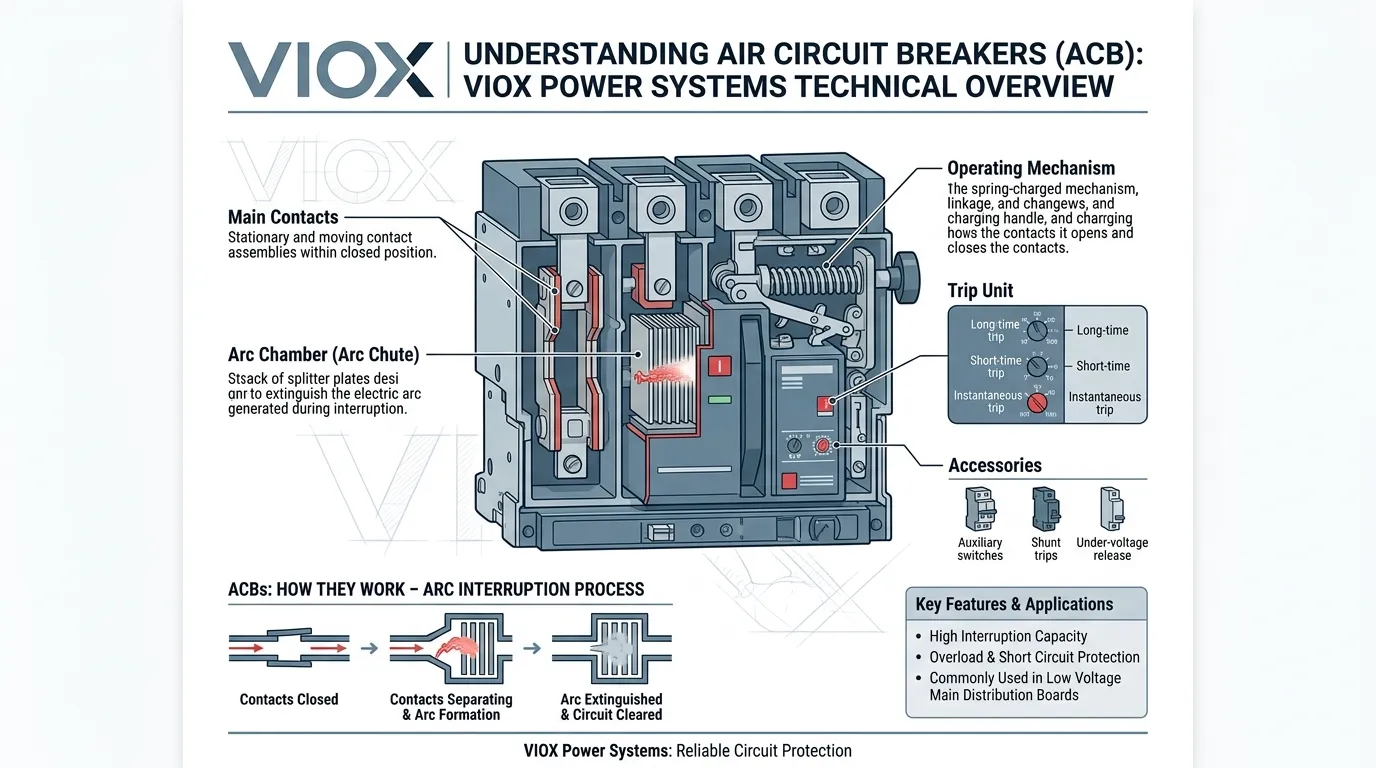
    Technical infographic showing the main parts of an air circuit breaker
    Technical breakdown showing the essential internal components of an air circuit breaker, including the arc chute, operating mechanism, and electronic trip unit.

    Every modern air circuit breaker contains the same fundamental sections, regardless of manufacturer.

    Main contacts are the primary current-carrying elements, typically made from silver-plated copper with contact surfaces engineered for low resistance under continuous load. Their design directly affects thermal performance, reliability, and service life.

    Arc contacts and arc chamber manage the electrical arc that forms when the breaker opens. The arc contacts separate last, drawing the arc away from the main contacts. The arc is then guided into an arc chamber (arc chute) — typically a stack of insulated metal splitter plates — where it is stretched, cooled, split into smaller series arcs, and extinguished. This design allows the breaker to interrupt high fault currents using only atmospheric air.

    Operating mechanism stores and releases the mechanical energy needed to open and close the breaker. Most modern ACBs use spring-charged mechanisms, with closing springs charged manually or electrically. The mechanism provides manual and electrical control interfaces for local or remote operation.

    Trip unit is the protection brain of the breaker. In modern ACBs, this is almost universally electronic — a microprocessor-based controller using current transformers to measure phase currents and evaluate them against user-adjustable protection settings. This provides precise adjustment of pickup currents and time delays, enabling coordination with upstream and downstream devices.

    Accessories and releases expand functionality within larger power distribution systems. Common accessories include shunt release (remote tripping), undervoltage release (voltage drop protection), auxiliary contacts (status signals), motor operators (remote closing), and communication modules (Modbus, Profibus, Ethernet integration for monitoring and control).

    Fixed vs Draw-Out ACB

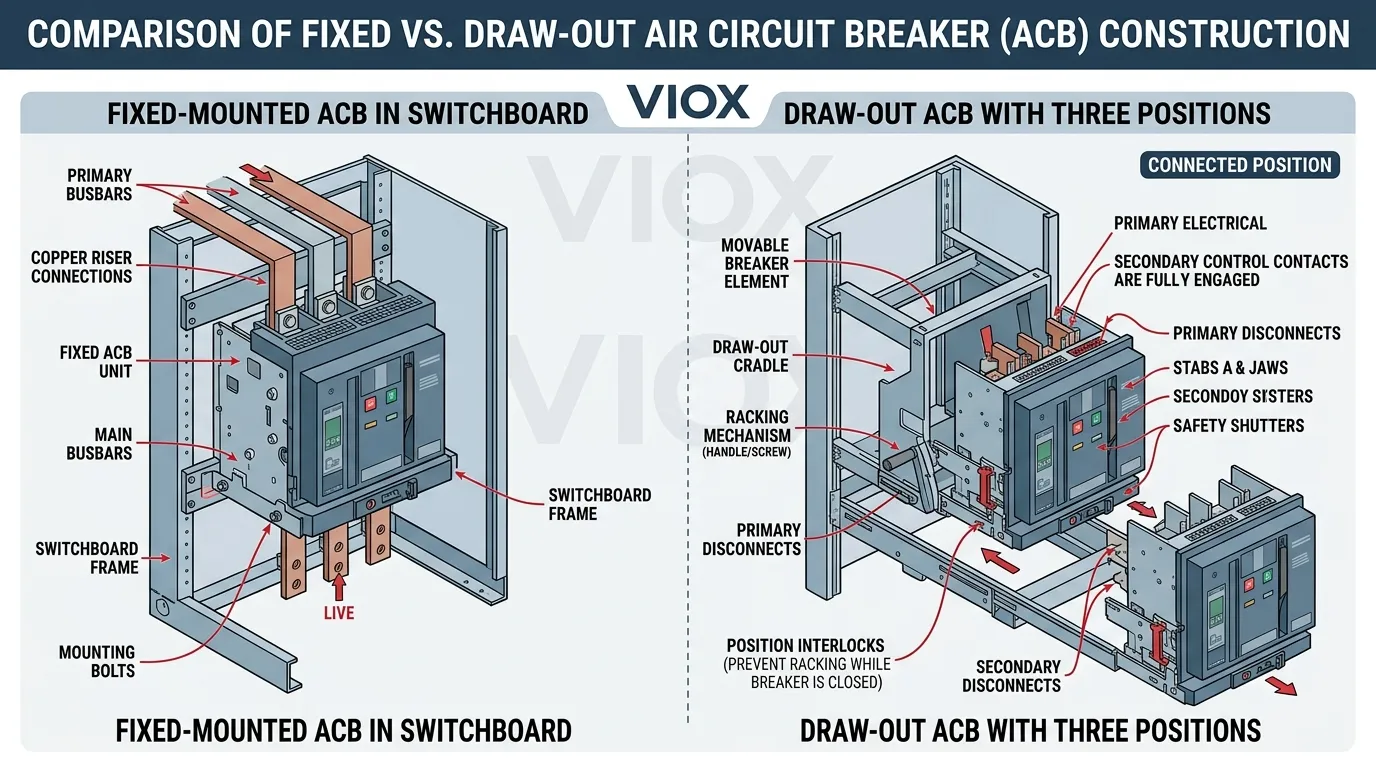
    Technical diagram showing fixed and draw-out air circuit breaker configurations
    Visual comparison highlighting the structural, mounting, and maintenance access differences between fixed-mounted and draw-out air circuit breaker setups.

    One of the most consequential decisions in air circuit breaker selection is whether to specify a fixed or draw-out configuration.

    Fixed ACB is mounted permanently into the switchboard structure. The breaker cannot be removed without disconnecting and unbolting its connections. Fixed ACBs have simpler mechanical structure and lower installed cost, making them practical for projects where withdrawal for testing or maintenance is not a core requirement, or where planned shutdown-based maintenance is acceptable.

    Draw-out ACB is mounted in a standardized cradle or drawer system. The breaker can be moved between defined service positions — connected (normal operation), test (main circuit disconnected, auxiliary circuits energized for trip testing), and disconnected (fully withdrawn for inspection or replacement) — without tools and without disassembling the switchboard.

    Draw-out types improve maintenance flexibility and operational safety significantly. The breaker can be tested while the bus remains energized, replaced quickly with a spare to minimize downtime, and inspected away from energized bus bars. Operating positions include mechanical and electrical interlocks preventing unsafe operations. Draw-out ACBs are standard in critical systems — data centers, hospitals, continuous-process manufacturing — where testing speed, maintenance access, and downtime reduction are priorities.

    Trip Unit Basics

    For many engineers, the trip unit is the most important practical component of an air circuit breaker. It determines how the breaker responds to fault conditions and coordinates with other protection devices.

    A modern ACB trip unit continuously monitors current through the breaker using internal current transformers. When measured current exceeds a programmed threshold for a programmed duration, the trip unit commands the breaker to open. The key advantage is adjustability: each protection function can be independently configured with its own pickup level and time delay.

    Standard protection functions are organized into a well-established framework:

    • Long-time overcurrent protection (L) handles sustained overload conditions. Pickup is typically adjustable from 0.4× to 1.0× rated current (per IEC 60947-2), with time delays from seconds to minutes, allowing the breaker to ride through normal load transients while clearing persistent overloads.
    • Short-time overcurrent protection (S) addresses moderate fault currents. The adjustable pickup and time delay allow the ACB to delay tripping briefly to see if a downstream breaker clears the fault first — the essence of time-graded selectivity.
    • Instantaneous protection (I) provides immediate tripping at very high fault currents where there is no time for selectivity.
    • Ground fault protection (G), where provided, detects current leaking to earth and trips the breaker to limit fire and shock risk.

    These functions are grouped as LSI or LSIG (adding ground fault). Advanced trip units may also provide energy metering, power quality monitoring, demand monitoring, event logging, and communication interfaces for SCADA or building management system integration.

    Frequently Asked Questions

    What is an air circuit breaker?

    An air circuit breaker is a low-voltage circuit breaker that uses air at atmospheric pressure to extinguish the electrical arc formed when the breaker opens. ACBs are designed for high-current commercial and industrial power distribution systems, typically serving as main switchboard incomers, bus couplers, and section breakers.

    What is the difference between ACB and MCCB?

    An ACB is typically used at the main switchboard or incomer level, offering higher current capacity (commonly 630–6300 A), more advanced adjustable protection, and draw-out mounting options. An MCCB is more commonly used on feeders and downstream distribution circuits (16–2500 A), with a more compact form factor. In most systems, the two breaker types work together at different levels of the protection hierarchy.

    Where are air circuit breakers used?

    Air circuit breakers are used in main low-voltage switchboards, generator and transfer switchboards, bus coupler sections, motor control centers, and large commercial or industrial distribution systems. They are installed wherever the system current exceeds the practical range of MCCBs and wherever adjustable, coordinated protection is required.

    What is the difference between fixed and draw-out ACB?

    A fixed ACB is permanently mounted in the switchboard and cannot be removed without disconnecting its terminals. A draw-out ACB can be moved between connected, test, and disconnected positions within a standardized cradle, allowing testing, inspection, and replacement without disassembling the switchboard. Draw-out types are preferred in critical systems where maintenance access and minimized downtime are priorities.

    Is an ACB a low-voltage or medium-voltage breaker?

    An air circuit breaker is a low-voltage device, typically rated for systems up to 690 V AC per IEC 60947-2. Medium-voltage applications (3.3 kV and above) are served by vacuum circuit breakers (VCBs), SF6 circuit breakers, and other breaker families designed for that voltage class.

    Why do ACBs use electronic trip units?

    Electronic trip units provide adjustable and more precise protection compared to traditional thermal-magnetic elements. This adjustability is essential for selectivity and coordination in larger power distribution systems, where the ACB’s trip settings must be configured to work in concert with downstream MCCBs and MCBs. Electronic trip units also enable advanced features such as ground fault protection, energy metering, event logging, and communication with supervisory systems.

    What is the rated current range of an air circuit breaker?

    Most air circuit breaker families cover rated currents from 630 A to 6300 A, though specific ranges vary by manufacturer and product series per IEC 60947-2. The frame size determines the maximum rated current the breaker can carry, while the trip unit setting determines the actual protection threshold within that frame.

    How long does an air circuit breaker last?

    With proper maintenance per manufacturer specifications, an ACB can remain in service for 20 to 30 years or more. Electrical life — the number of operations under load or fault conditions — typically ranges from 10,000 to 20,000 operations depending on the interrupted current and manufacturer design. Mechanical life for no-load operations is significantly higher. Regular inspection of contacts, arc chambers, and operating mechanisms is essential to achieving full expected service life.

  • Why Top Hat DIN Rails (TH35) Are the Industry Standard

    Why Top Hat DIN Rails (TH35) Are the Industry Standard

    Bottom Line Up Front: The top hat section (TH35) became the industry standard for DIN rails due to its symmetrical design, universal 35mm width, modular compatibility with 18mm component widths, and superior ease of installation compared to earlier G-section and C-section rails.

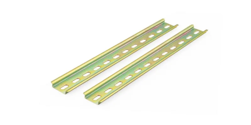
    din rail 800_400

    The top hat section DIN rail, officially designated as TH35 or TS35, has emerged as the dominant mounting solution in industrial electrical applications worldwide. Top hat sections are broadly considered the industry standard in DIN rail terms, and are the type you’ll likely find most readily available. Understanding why this particular profile achieved such widespread adoption reveals the evolution of electrical panel design and the practical benefits that drive industrial standardization.

    Historical Development: From G-Section to Top Hat Dominance

    The story of DIN rail standardization begins in 1928 Germany, when the original concept was developed and implemented in Germany in 1928, and was elaborated into the present standards in the 1950s. The original concept of the rail had a G-shaped profile, which provided a firm mechanical connection, prevented backward installation and allowed for fine positional adjustment of the terminal blocks as they could slide along it laterally.

    However, the G-section design had limitations. The G-section rail and its components were soon adopted by other electrical manufacturers, and were later joined by the so-called “top-hat” profile design, a symmetrical version of the rail more suited to the mounting of lighter components. This evolution marked a crucial turning point in industrial mounting solutions.

    Key Advantages That Made Top Hat the Standard

    1. Symmetrical Design for Universal Installation

    The most significant advantage of the top hat section lies in its symmetrical profile. Top hat design is a symmetrical installation rail and industry standard symmetrical rail that eliminates installation confusion. Unlike asymmetrical G-section rails, components can be mounted from either direction, reducing installation errors and simplifying training for technicians.

    2. Optimal 35mm Width Standard

    The 35mm width of top hat rails represents the perfect balance between versatility and space efficiency. This 35 mm wide rail is widely used to mount circuit breakers, relays, programmable logic controllers, motor controllers, and other electrical equipment. This standardized width became universally adopted because it accommodates the vast majority of industrial electrical components while maintaining compact panel layouts.

    3. Modular Component System

    Perhaps the most ingenious aspect of the top hat standard is its modular approach. The width of devices that are mounted on a 35 mm “top hat” DIN rail generally use “modules” as a width unit, one module being 18 mm wide. For example, a small device (e.g. a circuit breaker) may have a width of 1 module (18 mm wide), while a larger device may have a width of 4 modules (4 × 18 mm = 72 mm).

    This modular system creates a standardized ecosystem where:

    • Space planning becomes predictable – engineers can calculate exact panel requirements
    • Component interchangeability is guaranteed across manufacturers
    • Efficient space utilization is maximized in control panels

    4. Cross-Manufacturer Compatibility

    The top hat standard’s greatest strength lies in its universal adoption. The fact that DIN rail systems are today recognised as a range of fixed and consistent standards means that installers can be guaranteed dimensional uniformity across a whole suite of relevant products, regardless of whichever company is handling manufacture or supply of various individual parts.

    This interoperability provides several critical benefits:

    • Design flexibility without vendor lock-in
    • Cost optimization through competitive sourcing
    • Future expansion capabilities with any manufacturer’s components
    • Reduced inventory complexity for maintenance teams

    Technical Specifications That Define the Standard

    Standard Dimensions and Variations

    Top hat rails are manufactured in two primary depth configurations:

    • Standard depth: 7.5mm – 7.5mm (Standard): Designated IEC/EN 60715 – 35 × 7.5. Suitable for the majority of general-purpose applications.
    • Deep hat: 15mm – 15mm (Deep Hat): Designated IEC/EN 60715 – 35 × 15. This deeper profile provides greater strength and rigidity for mounting heavier components or spanning wider distances between mounting points.

    Material and Construction Standards

    The most common material used for manufacturing DIN rails is cold-rolled carbon steel sheet. The standard construction process involves zinc plating for corrosion resistance, ensuring long-term reliability in industrial environments.

    Installation and Operational Benefits

    Rapid Component Mounting

    The top hat design enables exceptionally efficient installation processes. They save time and work – components simply snap or slide into place on the rail, rather than having to panel mount each individual component separately. This snap-on capability dramatically reduces assembly time compared to traditional mounting methods that require individual component securing.

    Space Optimization

    Saves space – DIN rail terminals and smaller DIN mounted components can be packed into smaller spaces. The compact profile of top hat rails maximizes usable panel space while maintaining structural integrity for mounted components.

    Maintenance Accessibility

    The standardized mounting system simplifies ongoing maintenance operations. Components can be easily removed, replaced, or relocated without panel modifications, reducing downtime and maintenance costs.

    Industry Applications Driving Standard Adoption

    Industrial Automation Systems

    TS35 DIN rail is very commonly used for mounting a wide range of electrical industrial control products and components, from circuit breakers and motor controllers to remote I/O, transformers, drives and much more. The modular nature perfectly suits modern automation requirements where components frequently need updating or expansion.

    Building Management Systems

    Commercial and residential building automation increasingly relies on DIN rail mounting for HVAC controls, lighting systems, and energy management equipment. The top hat standard’s reliability and expandability make it ideal for these evolving applications.

    Power Distribution and Control

    Electrical distribution panels worldwide have standardized on top hat rails for mounting protective devices, meters, and control equipment. The universal compatibility ensures consistent installation practices across different countries and applications.

    Comparison with Alternative DIN Rail Profiles

    C-Section Rails: Legacy Applications

    C30-15L(1.5) Aluminum alloy Din rail

    TS32 DIN rails are 32mm wide from edge to edge, and have a C-shaped cross-section with a symmetrical curve to their outer edges. This is generally seen today as an older standard of DIN rail mounting system, which was more common during the earlier years of universal adoption but has now been surpassed by the TS35 variant.

    C-section rails require adapters for modern components, adding complexity and cost to installations.

    G-Section Rails: Specialized Heavy-Duty Use

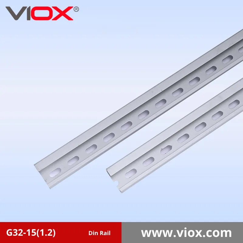
    G32-15L(1.2) Aluminum alloy Din Rail

    G rail is generally used to hold heavier, higher-power components. It is mounted with the deeper side at the bottom, and equipment is hooked over the lip, then rotated until it clips into the shallower side. While still used for specific heavy-duty applications, G-rails lack the versatility and ease of installation that makes top hat rails the preferred choice for most applications.

    Global Standards and Compliance

    The top hat section’s industry standard status is reinforced by comprehensive international standards:

    • European Standard EN 50022: Specification for low voltage switchgear and control-gear for industrial use. Mounting rails. Top hat rails 35 mm wide for snap-on mounting of equipment.
    • IEC International Standard 60715: Dimensions of low-voltage switchgear and control-gear. Standardized mounting on rails for mechanical support of electrical devices in switchgear and control-gear installations.
    • Multiple national standards including DIN 46277-3, BS 5584, and AS 2756.1997

    These standards ensure global interoperability and consistent manufacturing specifications worldwide.

    Future-Proofing Through Standardization

    Industry 4.0 Integration

    While top hat rails have already been used for a long time within industry 4.0, they are still highly relevant. Modules responsible for communication between human and machine (like network sockets) are all available in accordance with necessary standards for mounting on top hat rails.

    Emerging Technologies Compatibility

    Modern automation components, IoT devices, and smart building technologies continue to adopt the top hat mounting standard, ensuring that existing infrastructure remains compatible with advancing technology.

    Economic Impact of Standardization

    The adoption of top hat rails as the industry standard has delivered significant economic benefits:

    • Reduced installation costs through simplified mounting procedures
    • Lower inventory requirements due to universal compatibility
    • Decreased training needs with standardized installation methods
    • Enhanced system reliability through proven mounting solutions
    • Simplified maintenance operations with interchangeable components

    Conclusion: The Clear Choice for Modern Applications

    The top hat section (TH35) achieved industry standard status through a combination of practical design advantages, universal compatibility, and economic benefits that address real-world installation and maintenance challenges. Its symmetrical profile, modular component system, and comprehensive standards compliance make it the logical choice for electrical professionals worldwide.

    Despite being underrated by some, DIN rails offer a crucial performance at all kinds of electrical installations. They save time, space, and money, all while ensuring that the project remains unified under international standards and easily upscalable for the future.

    For engineers, electricians, and system designers, understanding why the top hat section became the standard provides insight into selecting the most effective mounting solutions for modern electrical installations. The overwhelming adoption of this profile reflects not just historical precedent, but continuing practical advantages that will likely maintain its dominance in industrial applications for decades to come.

    Related

    How to Determine the Quality of a DIN Rail

    DIN Rail vs. Traditional Mounting

    Top 5 Reasons Why DIN Rails Are Essential in Modern Electrical Installations

    What Is DIN Rail?

  • How Circuit Breaker Poles Affect Voltage & Current Protection

    How Circuit Breaker Poles Affect Voltage & Current Protection

    Introduction

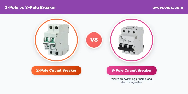
    Understanding circuit breaker pole configurations is crucial for electrical safety and system efficiency. The number of poles in a circuit breaker refers to the number of circuits the device can protect, with each pole representing individual switches within the breaker that correspond to different wires or phases of electricity. Whether you’re working with residential, commercial, or industrial electrical systems, choosing the correct pole configuration directly impacts voltage delivery, current protection, and overall system safety.

    What Are Circuit Breaker Poles?

    1P-4P Circuit Breaker Poles

    Poles are the number of completely separate circuits that can be simultaneously protected by a circuit breaker. Think of each pole as an individual switch within the breaker that can interrupt electrical flow independently while being mechanically linked to other poles for coordinated protection.
    Key Characteristics of Poles:

    • Electrical Isolation: Each pole operates on separate circuits
    • Mechanical Linkage: Multi-pole breakers trip together when one pole detects a fault
    • Voltage Distribution: Different pole configurations provide different voltage outputs
    • Protection Scope: More poles can protect additional conductors including neutral wires

    Single Pole Circuit Breakers (1P)

    Voltage and Current Specifications

    Single-pole breakers provide 120 volts, typically rated for 15-20 amps, and have one hot wire and one neutral wire. These are the most common breakers found in residential electrical panels.

    Applications and Protection Features

    Ideal for:

    • Standard residential lighting circuits
    • General purpose outlets
    • Small appliances (televisions, computers, small power tools)
    • Circuits requiring 120V power supply

    Protection Characteristics:

    • Protects only the hot conductor
    • If a single-pole breaker overloads, only the affected circuit breaker will trip
    • Most energy-efficient option for low-power applications
    • Takes up one slot in electrical panel

    Wiring Configuration

    Single-pole breakers are wired with one hot wire and one neutral wire, making them simple to install and maintain for basic electrical circuits.

    Double Pole Circuit Breakers (2P)

    Voltage and Current Specifications

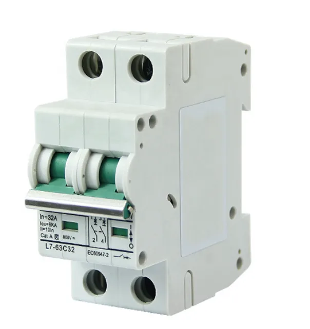
    Double-pole breakers provide 240 volts, 20-60 amps and have two hot wires that share one neutral wire. These breakers are essential for high-power residential and commercial applications.

    Applications and Protection Features

    Ideal for:

    • Electric ranges and ovens
    • Central air conditioning systems
    • Electric water heaters
    • Clothes dryers
    • Hot tubs and spas
    • Large motor applications

    Protection Characteristics:

    • If there’s a short circuit on either of the poles’ hot wires, both trip
    • Provides simultaneous disconnection of both hot conductors
    • Takes up two slots in the breaker box with a toggle switch that’s twice the length

    Wiring Configuration

    Double-pole breakers are wired with two hot wires connected by a single neutral wire, enabling 240V operation by utilizing both legs of residential electrical service.

    Three Pole Circuit Breakers (3P)

    Voltage and Current Applications

    Three-pole breakers are primarily used in three-phase electrical systems common in commercial and industrial settings. A 3-pole circuit breaker is used primarily in three-phase electrical systems, which are common in large buildings and industrial applications.

    Protection Features

    Key Benefits:

    • Protects all three phases simultaneously
    • Can interrupt the circuit in all three phases simultaneously, providing comprehensive protection against overloads and short circuits
    • More efficient power distribution for motors and large equipment
    • Reduces electrical panel space compared to three separate single-pole breakers

    When to Use 3P Breakers

    TP MCB is used in 3phase 4wire system and is most commonly used type in all ordinary three phase supply. These are ideal for:

    • Three-phase motors
    • Industrial machinery
    • Commercial HVAC systems
    • Distribution panels in commercial buildings

    Four Pole Circuit Breakers (4P)

    Enhanced Protection Features

    A 4-pole circuit breaker offers similar functionality to a 3-pole breaker, with an additional pole for neutral line protection. This additional protection becomes crucial in specific electrical scenarios.

    Critical Applications

    When 4P Breakers Are Essential:

    Unbalanced Load Systems:

    In systems with unbalanced loads, where the load on one or more phases is significantly different from the others, a fault condition can cause current to flow through the neutral wire.

    Harmonic Current Protection:

    Certain types of equipment, such as computers and energy-efficient lighting, can generate harmonic currents that can cause the neutral wire to carry higher levels of current.

    Dual Power Source Systems:

    Where we have dual power like in DG & other electricity supply sources, it is required to isolate neutral, where neutral needs to be isolated in internal network TPN MCB or 4P MCB can be used.

    TPN vs 4P Distinction

    TPN means a 4 Pole device with 4th Pole as Neutral. For TPN, protection applies to the current flows through only 3 poles (Three Phase) only; there is no protection for the current flow through the neutral pole. For the 4 pole breakers, protection applies to current flow through all poles.

    Voltage Protection Differences by Pole Configuration

    Voltage ratings for different pole configurations

    Single-Phase Systems (1P and 2P)

    • 120V Protection: Single pole breakers protect individual 120V circuits
    • 240V Protection: Double pole breakers provide protection for 240V loads by protecting both hot conductors

    Three-Phase Systems (3P and 4P)

    • Phase Protection: Three-pole breakers protect the three phase conductors
    • Complete System Protection: Four-pole breakers add neutral protection for comprehensive system safety

    Current Protection Capabilities

    Maximum current ratings for different pole configurations

    Coordination and Selectivity

    Multi-pole circuit breakers are electrically isolated, but mechanically linked, designed with a “common trip” linkage that ensures that if one pole trips in the breaker, the other poles in the breaker will trip simultaneously.

    Protection Philosophy Differences

    • Single/Double Pole: Focuses on individual circuit protection
    • Three Pole: Emphasizes balanced three-phase protection
    • Four Pole: Provides comprehensive protection including neutral fault protection

    Safety Considerations and Code Requirements

    Ground Fault Protection

    If unrestricted ground fault protection is fitted to the transformer neutral, then the bus section circuit breaker should have 4-poles and preferably incomer circuit breakers should also have 4-poles.

    Neutral Wire Safety

    Normally, Neutral is not allowed to break in any conditions, (except special applications) for human & equipment safety. However, specific applications require neutral switching for complete isolation.

    Trip-Free Mechanisms

    All circuit breakers are designed with an internal trip-free mechanism, a safety feature making it impossible to manually hold the contacts closed during overcurrent or fault conditions.

    Choosing the Right Pole Configuration

    Decision Matrix

    Use Single Pole When:

    • 120V circuits required
    • Individual circuit protection needed
    • Residential lighting and small appliances
    • Cost efficiency is priority

    Use Double Pole When:

    • 240V operation required
    • High-power residential appliances
    • Need simultaneous disconnection of both hot wires

    Use Three Pole When:

    • Three-phase system operation
    • Balanced load applications
    • Standard commercial/industrial installations
    • Neutral remains on common bus

    Use Four Pole When:

    • Unbalanced three-phase loads present
    • Harmonic currents expected
    • Dual power source configurations
    • Complete electrical isolation required
    • Sensitive equipment protection needed

    Installation and Maintenance Best Practices

    Panel Space Requirements

    • Single pole: 1 panel slot
    • Double pole: 2 panel slots
    • Three pole: 3 panel slots
    • Four pole: 4 panel slots

    Professional Installation Recommendations

    System evaluation has to be required to decide whether three-pole circuit breakers plus neutral link can be used or four-pole breakers are required.

    Code Compliance

    Always consult local electrical codes and standards when selecting circuit breaker pole configurations. Professional evaluation ensures proper protection coordination and system safety.

    Conclusion

    The number of poles in circuit breakers significantly impacts both voltage delivery and current protection capabilities. Single and double pole breakers serve residential needs effectively, while three and four pole configurations provide the comprehensive protection required for commercial and industrial applications.

    Key takeaways for electrical professionals:

    • Match pole configuration to system voltage requirements
    • Consider load characteristics and balance when choosing 3P vs 4P
    • Evaluate neutral current potential in harmonic-rich environments
    • Ensure proper coordination with upstream and downstream protective devices

    Understanding these differences enables informed decisions that enhance electrical system safety, reliability, and code compliance across all installation types.

    Related

    How to Choose the Right Miniature Circuit Breaker: Complete Technical Guide

    2-Pole vs 3-Pole Breaker: Complete Guide

    How to Replace a Circuit Breaker

    What is a DC Circuit Breaker

  • 2-Pole vs 3-Pole Breaker: Complete Guide

    2-Pole vs 3-Pole Breaker: Complete Guide

    Choosing the wrong circuit breaker type can be dangerous, costly, and may violate electrical codes. Understanding the difference between 2-pole and 3-pole breakers is essential for electrical safety, proper appliance operation, and code compliance. Whether you’re installing new equipment, upgrading your electrical panel, or simply want to understand your home’s electrical system better, this comprehensive guide will explain everything you need to know about these two critical breaker types.

    In this article, you’ll discover the key differences between 2-pole and 3-pole circuit breakers, when to use each type, safety considerations, and installation requirements that could save you from electrical hazards and expensive mistakes.

    What is a Circuit Breaker and Why Type Matters

    MCB Pole Configurations

    Basic Circuit Breaker Function

    Circuit breakers serve as the first line of defense against electrical overloads, short circuits, and potential electrical fires in your home or business. These safety devices automatically interrupt electrical flow when they detect dangerous conditions, protecting both your electrical system and connected appliances.

    Unlike fuses that burn out and require replacement, circuit breakers can be reset after tripping, making them more convenient and cost-effective for long-term use. Modern electrical panels rely on different breaker types to handle various voltage requirements and electrical loads throughout your property.

    The Importance of Choosing the Right Type

    Selecting the appropriate breaker type isn’t just about compatibility—it’s about safety and efficiency. The wrong breaker can fail to protect your equipment, cause appliances to malfunction, or create serious fire hazards. Understanding voltage requirements, phase configurations, and specific applications ensures your electrical system operates safely and meets current electrical codes.

    Understanding 2-Pole Circuit Breakers

    What is a 2-Pole Breaker?

    L7-63 DC MCB

    A 2-pole circuit breaker is designed to handle 240-volt electrical circuits commonly found in residential applications. These breakers occupy two slots in your electrical panel and connect to two hot wires, providing double the voltage of standard 120-volt single-pole breakers.

    Physically, 2-pole breakers appear as double-width units with a connecting handle or tie bar that ensures both sides trip simultaneously if an overload occurs on either circuit. This design provides balanced protection for high-voltage appliances that require 240 volts to operate efficiently.

    How 2-Pole Breakers Work

    2-pole breakers work by connecting to two separate hot bus bars in your electrical panel, each carrying 120 volts. When combined, these create the 240-volt supply needed for larger appliances. The breaker monitors electrical flow through both hot wires and will trip if it detects an overload, short circuit, or ground fault on either side.

    Most 2-pole breaker applications don’t require a neutral wire connection at the breaker itself, though the connected appliance may use a neutral wire for specific functions like digital displays or control circuits.

    Common Applications for 2-Pole Breakers

    • Electric Water Heaters: Most residential water heaters require 240 volts and typically use 20-30 amp 2-pole breakers, depending on the heater’s wattage rating.
    • Central Air Conditioning Units: AC condensers usually need 240-volt power and commonly use 30-60 amp 2-pole breakers based on the unit’s cooling capacity.
    • Electric Dryers: Standard electric clothes dryers operate on 240 volts and typically require 30-amp 2-pole breakers.
    • Electric Ranges and Ovens: Kitchen ranges and wall ovens generally use 40-50 amp 2-pole breakers to handle their high power requirements.
    • Pool Equipment: Pool pumps, heaters, and other equipment often require 240-volt power through appropriately sized 2-pole breakers.
    • Workshop Equipment: Large tools like table saws, welders, and compressors frequently need 240-volt power for optimal performance.

    Understanding 3-Pole Circuit Breakers

    What is a 3-Pole Breaker?

    A 3-pole circuit breaker is designed primarily for three-phase electrical systems commonly found in commercial and industrial settings. These breakers occupy three slots in an electrical panel and can handle various voltage configurations including 208V, 240V, and 480V, depending on the specific application and electrical system design.

    3-pole breakers feature three separate switching mechanisms connected by a common trip bar, ensuring that all three phases disconnect simultaneously if a fault occurs on any single phase. This coordinated protection is essential for three-phase motors and equipment that require balanced power across all three phases.

    How 3-Pole Breakers Work

    3-pole breakers connect to three separate hot bus bars in a three-phase electrical panel. In a typical three-phase system, each hot wire carries power that’s 120 degrees out of phase with the others, creating a more efficient and balanced power delivery system than single-phase residential power.

    The breaker continuously monitors all three phases and will trip if it detects an imbalance, overload, or fault condition on any phase. This protection is crucial because three-phase equipment can be damaged by single-phase operation or significant phase imbalances.

    Common Applications for 3-Pole Breakers

    • Commercial HVAC Systems: Large rooftop units and commercial air conditioning systems typically require three-phase power for efficient operation and use appropriately sized 3-pole breakers.
    • Industrial Motors: Three-phase motors are common in manufacturing, pumping applications, and industrial equipment due to their efficiency and smooth operation.

    • Commercial Kitchen Equipment: Large commercial ovens, dishwashers, and other restaurant equipment often operate on three-phase power.
    • Manufacturing Equipment: Production machinery, CNC equipment, and industrial tools frequently require three-phase power for optimal performance.
    • Data Centers: Large UPS systems and power distribution units in data centers commonly use three-phase power with 3-pole breaker protection.
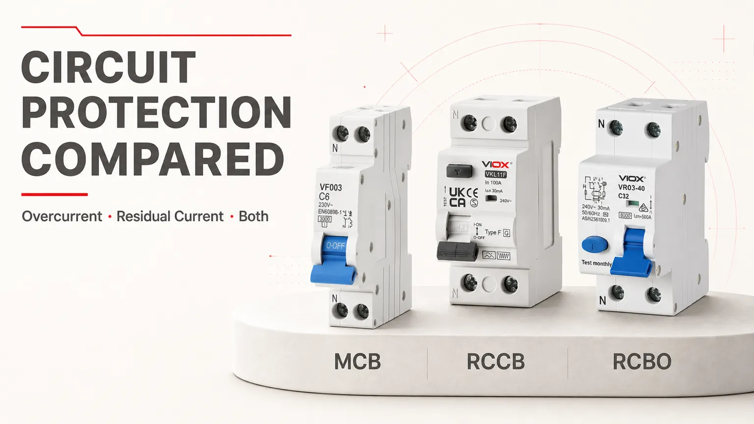
    breaker specifications comparison

    Key Differences Between 2-Pole and 3-Pole Breakers

    Physical Differences

    The most obvious difference between 2-pole and 3-pole breakers is their size and appearance in the electrical panel. 2-pole breakers occupy two adjacent slots and feature either a connecting handle or tie bar linking both sides. 3-pole breakers are noticeably wider, occupying three slots, and have three separate switching mechanisms with a common trip mechanism.

    Visual identification is straightforward: count the number of hot wire connections. 2-pole breakers have two hot wire terminals, while 3-pole breakers have three. The breaker labels should also clearly indicate the pole configuration and amperage rating.

    Electrical Differences

    • Voltage Configuration: 2-pole breakers typically provide 240 volts in residential applications, while 3-pole breakers can provide various voltages depending on the electrical system configuration—208V in wye systems, 240V in delta systems, or 480V in higher voltage applications.
    • Phase Relationships: 2-pole breakers work with single-phase power (two legs of a split-phase system), while 3-pole breakers work with true three-phase power where each phase is 120 degrees out of phase with the others.
    • Power Delivery: 3-pole systems provide more balanced power delivery and are more efficient for motor applications, while 2-pole systems are adequate for resistive loads like heating elements.

    Application Differences

    The primary application difference lies in the electrical system type and equipment requirements. 2-pole breakers are predominantly used in residential settings for high-voltage appliances that don’t require three-phase power. 3-pole breakers are mainly used in commercial and industrial applications where three-phase equipment provides better efficiency and performance.

    • Residential Focus: Most homes use single-phase electrical service, making 2-pole breakers the standard choice for 240-volt appliances.
    • Commercial Focus: Commercial buildings typically have three-phase electrical service, making 3-pole breakers necessary for proper equipment operation and protection.
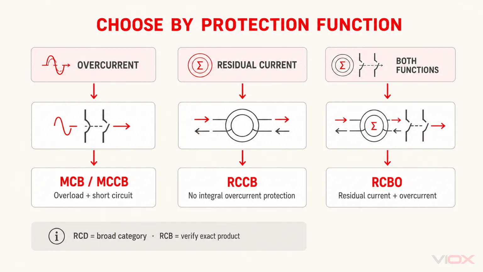
    When to Use Each Type of Breaker

    Residential Applications (2-Pole Focus)

    In residential settings, 2-pole breakers are the standard choice for appliances requiring 240 volts. Your electrical panel is designed around single-phase service, and virtually all residential appliances are manufactured for single-phase operation.
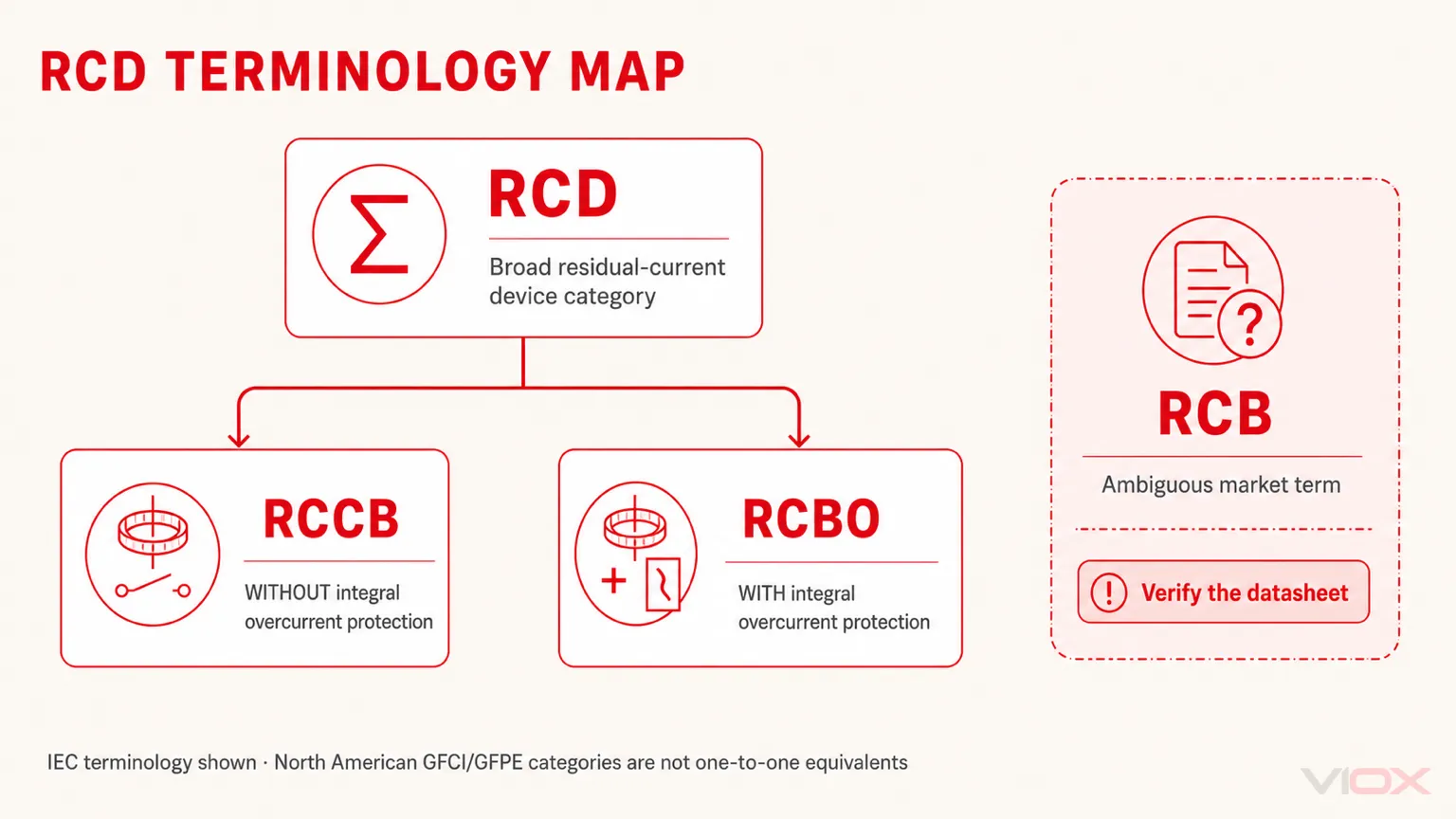
    • Standard Household Appliances: Electric water heaters, dryers, ranges, and central air conditioning units are designed for single-phase 240-volt operation and require 2-pole breakers.
    • Space Considerations: Residential electrical panels have limited space, and 2-pole breakers make efficient use of available slots while providing necessary protection.
    • Cost Effectiveness: 2-pole breakers are generally less expensive than 3-pole breakers and are readily available at most electrical supply stores.

    Commercial and Industrial Applications (3-Pole Focus)

    Commercial and industrial facilities typically have three-phase electrical service, making 3-pole breakers essential for proper equipment operation and protection.

    • Motor Applications: Three-phase motors are more efficient, produce less vibration, and have better starting characteristics than single-phase motors, making them preferred for commercial applications.
    • Heavy-Duty Equipment: Industrial equipment, large HVAC systems, and manufacturing machinery often require the balanced power delivery that only three-phase systems can provide.
    • Power Efficiency: Three-phase systems are more efficient for transmitting large amounts of electrical power, reducing operating costs in commercial settings.

    Making the Right Choice

    • Check Equipment Specifications: Always consult the manufacturer’s specifications for voltage, phase, and amperage requirements before selecting a breaker.
    • Understand Your Electrical System: Verify whether your building has single-phase or three-phase electrical service. Residential buildings almost always have single-phase service.
    • Consider Future Needs: If you’re upgrading equipment or expanding operations, consider whether your current electrical system can accommodate future requirements.
    • Professional Assessment: When in doubt, consult a qualified electrician who can assess your specific needs and ensure code compliance.

    Installation and Safety Considerations

    Professional Installation Requirements

    • Electrical Code Compliance: All breaker installations must comply with the National Electrical Code (NEC) and local building codes. These codes specify requirements for breaker sizing, wire sizing, and installation methods.
    • Permit Requirements: Many jurisdictions require electrical permits for breaker installations, especially for new circuits or panel modifications. Check with your local building department before beginning work.
    • Proper Sizing: Breakers must be properly sized for both the wire gauge and the connected load. Oversized breakers won’t provide adequate protection, while undersized breakers will trip unnecessarily.

    Safety Warnings and Precautions

    • Electrical Panel Dangers: Working inside electrical panels involves serious shock and electrocution risks. The main breaker should be shut off, but some circuits may remain energized even with the main breaker off.
    • Professional Installation Recommended: Unless you’re a qualified electrician, breaker installation should be left to professionals. Improper installation can create fire hazards, equipment damage, and safety risks.
    • Testing and Verification: After installation, circuits should be tested to verify proper operation, correct voltage, and adequate protection.

    Code Compliance and Regulations

    • AFCI and GFCI Requirements: Current electrical codes require Arc Fault Circuit Interrupter (AFCI) and Ground Fault Circuit Interrupter (GFCI) protection for many circuits. Some 2-pole and 3-pole breakers include these protective features.
    • Labeling Requirements: All breakers must be properly labeled to identify the circuits they protect. This labeling is essential for safety and maintenance purposes.
    • Inspection Requirements: Many installations require electrical inspection before energizing new circuits. Schedule inspections as required by local codes.

    Troubleshooting Common Breaker Issues

    Signs Your Breaker May Need Replacement

    • Frequent Tripping: If a breaker trips repeatedly without an obvious overload, it may be worn out or improperly sized for the circuit.
    • Physical Damage: Look for signs of burning, melting, or corrosion around breaker connections. These indicate serious problems requiring immediate professional attention.
    • Age-Related Concerns: Breakers installed more than 20-30 years ago may not meet current safety standards and should be evaluated for replacement.
    • Hot Spots: Breakers or connections that feel warm or hot indicate potential problems that require professional investigation.

    Compatibility Problems

    • Panel Compatibility: Not all breakers are compatible with all electrical panels. Use only breakers specifically approved for your panel manufacturer and model.
    • Amperage Mismatches: Breakers must match the wire size and connected load. Mismatched amperage ratings can create safety hazards.
    • Voltage Ratings: Ensure breakers are rated for the voltage they’ll be switching. Using inadequately rated breakers can cause failure and safety issues.

    Cost Considerations and Purchasing Guide

    Price Differences Between 2-Pole and 3-Pole Breakers

    • 2-Pole Breaker Costs: Standard 2-pole breakers typically range from $15-50, depending on amperage rating, brand, and special features like GFCI or AFCI protection.
    • 3-Pole Breaker Costs: 3-pole breakers are generally more expensive, ranging from $30-150 or more, depending on amperage, voltage rating, and manufacturer.
    • Quality Considerations: While generic breakers may be less expensive, name-brand breakers often provide better reliability and warranty coverage.

    Where to Buy and What to Look For

    • Electrical Supply Stores: Professional electrical supply houses typically stock a wider variety of breakers and can provide technical support.
    • Home Improvement Stores: Major retailers carry common breaker types but may have limited selection for specialized applications.
    • Online Retailers: Online purchasing can offer competitive prices but requires careful attention to compatibility and specifications.
    • Quality Certifications: Always choose breakers with UL (Underwriters Laboratories) listing or other recognized safety certifications.

    Frequently Asked Questions

    Can I Replace a 2-Pole with a 3-Pole Breaker?

    No, you cannot directly replace a 2-pole breaker with a 3-pole breaker in a residential electrical system. Residential panels are designed for single-phase service and don’t have the third hot bus bar required for 3-pole breaker operation. Additionally, residential appliances are designed for single-phase power and won’t operate properly on three-phase power.

    How Do I Know What Size Breaker I Need?

    Breaker sizing depends on the wire gauge and connected load. The breaker amperage should not exceed 80% of the wire’s ampacity for continuous loads, and should be sized according to the equipment manufacturer’s specifications. When in doubt, consult the National Electrical Code or a qualified electrician.

    Are Generic Breakers Safe to Use?

    Generic breakers can be safe if they’re UL-listed and compatible with your specific electrical panel. However, using breakers specifically approved by your panel manufacturer ensures optimal compatibility and performance. Never use non-compatible breakers, as this can create serious safety hazards.

    When Should I Upgrade My Electrical Panel?

    Consider upgrading your electrical panel if it’s over 30 years old, lacks adequate circuit capacity, uses outdated breaker types, or doesn’t meet current electrical codes. Signs that you need an upgrade include frequent breaker trips, flickering lights, or burning smells near the panel.

    Conclusion

    Understanding the difference between 2-pole and 3-pole breakers is essential for electrical safety and proper equipment operation. 2-pole breakers are the standard choice for residential 240-volt applications like water heaters, dryers, and air conditioning units, while 3-pole breakers are primarily used in commercial and industrial settings for three-phase equipment.

    The key differences lie in their electrical configuration, physical size, and intended applications. 2-pole breakers work with single-phase electrical systems common in homes, while 3-pole breakers require three-phase electrical service typically found in commercial buildings.

    Remember that electrical work carries inherent risks and often requires permits and professional installation. When selecting between 2-pole and 3-pole breakers, always consult equipment specifications, verify your electrical system configuration, and consider hiring a qualified electrician to ensure safe, code-compliant installation.

    For complex electrical projects or when you’re unsure about breaker selection, professional consultation isn’t just recommended—it’s essential for protecting your property and ensuring the safety of everyone who uses your electrical system.

    Related

    What Is the Difference Between MCB, MCCB, RCB, RCD, RCCB, and RCBO? Complete 2025

    China MCB Manufacturer

    How to Replace a Circuit Breaker

    Circuit Breakers vs Miniature Circuit Breakers: Complete Comparison Guide

    Types of Circuit Breakers

  • How Managing Two Separate Power Sources Improves Safety and System Stability

    How Managing Two Separate Power Sources Improves Safety and System Stability

    Managing two separate power sources through dual power automatic transfer switch systems represents a fundamental advancement in electrical safety and system reliability. This comprehensive analysis examines the mechanisms, benefits, and practical implications of dual power management for critical infrastructure and industrial applications.

    Enhanced Safety Through Redundancy and Risk Mitigation

    Elimination of Single Points of Failure

    The primary safety advantage of dual power systems lies in their ability to eliminate catastrophic single points of failure. Traditional single-source power systems create inherent vulnerabilities where any disruption to the primary power source results in complete system shutdown. Dual power systems address this fundamental weakness by providing an immediate backup source that can seamlessly take over operations when the primary source fails.

    Automatic transfer switches (ATS) play a crucial role in this safety enhancement by monitoring both power sources continuously and executing transfers without human intervention. This automation prevents the dangerous delays and human errors associated with manual switching during emergency situations. Healthcare facilities, in particular, benefit significantly from this capability, as evidenced by requirements that emergency power must be available within 10 seconds for life safety systems.

    Protection of Critical Safety Systems

    Dual power management ensures the continuous operation of essential safety systems that protect both personnel and equipment. Fire protection systems, emergency lighting, communication networks, and evacuation systems all require uninterrupted power to function effectively during emergencies. Research from industrial incidents demonstrates that power failures in safety-critical systems can lead to catastrophic consequences, including chemical releases, equipment damage, and personnel injuries.

    The seamless transition capability of modern automatic transfer switches, with response times as fast as 0.25 seconds for static transfer switches, ensures that safety systems remain operational even during the brief transition period between power sources. This rapid response is particularly critical for systems that cannot tolerate even momentary interruptions, such as hospital operating rooms and emergency communication systems.

    Compliance with Safety Standards and Regulations

    Dual power systems are essential for meeting stringent safety standards across multiple industries. The National Fire Protection Association’s NFPA 110 standard mandates specific requirements for emergency power systems in life safety applications, including transfer times, testing procedures, and maintenance schedules. Healthcare facilities must comply with additional standards that require redundant power sources for critical patient care areas.

    Industrial facilities handling hazardous materials are particularly subject to strict dual power requirements, as demonstrated by incidents where power failures led to the release of toxic substances due to failed containment systems. The European Union’s safety directives and similar international standards increasingly require dual power systems for facilities that pose significant environmental or safety risks.

    System Stability Enhancement Through Advanced Power Management

    Dramatic Improvement in Reliability Metrics

    The implementation of dual power systems results in substantial improvements across all key reliability metrics. Analysis of system performance data reveals that Mean Time Between Failures (MTBF) increases from 8,760 hours for single power supplies to 175,200 hours for advanced dual power systems with uninterruptible power supply (UPS) integration. This represents a 20-fold improvement in system reliability, translating directly to enhanced operational stability.

    Dual Power System Reliability Comparison: MTBF, Availability, and Downtime Analysis

    Dual Power System Reliability Comparison: MTBF, Availability, and Downtime Analysis

    System availability, a critical metric for mission-critical operations, improves from 99.95% for single power systems to 99.9997% for properly configured dual power systems. This improvement means annual downtime decreases from over 4 hours to less than 2 minutes, providing exceptional operational continuity for critical applications.

    Load Balancing and Power Quality Optimization

    Dual power systems enable sophisticated load balancing strategies that enhance overall system stability. By distributing electrical loads between multiple sources, these systems can optimize power utilization, reduce stress on individual components, and maintain more consistent voltage and frequency characteristics. This load sharing capability is particularly valuable in industrial environments where large, variable loads can cause significant power quality disturbances.

    Advanced dual power systems can also provide power factor correction and harmonic filtering, improving the overall quality of electrical power delivered to sensitive equipment. This enhanced power quality reduces equipment stress, extends operational lifespans, and minimizes the risk of power quality-related failures that could compromise system stability.

    Predictive Maintenance and Monitoring Capabilities

    Modern dual power systems incorporate sophisticated monitoring and diagnostic capabilities that enable predictive maintenance strategies. These systems continuously monitor power quality parameters, transfer switch performance, and backup power system status, providing early warning of potential issues before they result in system failures. This proactive approach significantly enhances system stability by preventing failures rather than simply responding to them.

    Remote monitoring capabilities allow facility managers to track system performance continuously and receive immediate alerts when anomalies are detected. This real-time visibility enables rapid response to emerging issues and supports data-driven maintenance decisions that optimize system reliability.

    Technical Mechanisms and Transfer Switch Technologies

    Automatic Transfer Switch Performance Characteristics

    Dual Power Automatic Transfer Switch 03

    The effectiveness of dual power systems depends heavily on the performance characteristics of their automatic transfer switches. Different ATS technologies offer varying levels of performance, with transfer times ranging from 300 seconds for manual systems to 0.25 seconds for static transfer switches.

    Automatic Transfer Switch Performance: Transfer Time vs Reliability

    Automatic Transfer Switch Performance: Transfer Time vs Reliability

    Static transfer switches represent the most advanced technology, using solid-state switching components to achieve near-instantaneous transfer times while maintaining 99.9% reliability. These systems are particularly valuable for applications requiring uninterrupted power, such as data centers and critical manufacturing processes.

    Standard automatic transfer switches, while having longer transfer times of approximately 10 seconds, offer excellent reliability at 99.5% while requiring minimal maintenance. These systems represent the optimal balance of performance and cost for most commercial and industrial applications.

    Power Source Integration and Management

    Effective dual power management requires careful integration of diverse power sources, including utility feeds, backup generators, and energy storage systems. Modern systems can seamlessly integrate renewable energy sources such as solar photovoltaic systems, creating hybrid power architectures that enhance both sustainability and reliability.

    Battery-based uninterruptible power supplies provide additional stability by bridging the gap during transfer operations and providing ride-through capability for brief power disturbances. The integration of multiple technologies creates layered protection that dramatically improves overall system stability and reliability.

    Economic Justification and Cost-Benefit Analysis

    Sector-Specific Economic Impact of Power Outages

    The economic impact of power outages varies dramatically across different sectors, providing clear justification for dual power system investments. Data centers experience the highest impact at \$82,000 per kW-hour of outage, while hospitals face costs of \$41,000 per kW-hour. Even industrial facilities, with relatively lower per-hour costs of \$13.93 per kW-hour, can face substantial losses due to longer average outage durations.

    Economic Impact of Power Outages by Sector: Cost per kW per Hour

    Economic Impact of Power Outages by Sector: Cost per kW per Hour

    Commercial facilities experience intermediate but still significant costs, with large commercial operations facing \$16,374 per kW-hour of outage. These high costs reflect the complex interdependencies of modern business operations and the cascading effects of power interruptions on productivity, equipment, and customer relationships.

    Return on Investment Analysis

    The economic analysis demonstrates compelling return on investment periods for dual power systems across most sectors. Data centers and hospitals typically achieve payback periods of 1-2 months, reflecting both the high cost of outages and the relatively low frequency of extended power disruptions in properly designed dual power systems.

    Industrial facilities achieve typical ROI periods of 3 months, while large commercial operations see 4-month payback periods. Even small commercial operations, despite lower absolute outage costs, achieve reasonable 8-month ROI periods due to the relatively modest incremental cost of basic dual power systems.

    Long-term Economic Benefits

    Beyond the immediate outage cost avoidance, dual power systems provide long-term economic benefits through improved equipment longevity, reduced maintenance costs, and enhanced operational flexibility. The improved power quality and reduced stress on electrical equipment result in longer service lives and lower replacement costs over time.

    Insurance considerations also favor dual power implementations, with many insurers offering reduced premiums for facilities with proper backup power systems. These ongoing cost reductions contribute to the long-term economic attractiveness of dual power investments.

    Real-World Applications and Case Studies

    Healthcare and Critical Infrastructure

    Healthcare facilities represent one of the most demanding applications for dual power systems, where failure can directly impact patient safety and care outcomes. Modern hospitals implement sophisticated dual power architectures that include multiple utility feeds, backup generators, and distributed UPS systems to ensure continuous power for life support, surgical equipment, and critical patient monitoring systems.

    Case studies from major medical centers demonstrate the critical importance of proper dual power design and maintenance. Facilities that have experienced power system failures often faced significant consequences, including patient evacuations, cancelled surgeries, and compromised patient care. Properly designed and maintained dual power systems have prevented such incidents even during major natural disasters and grid failures.

    Data Centers and Information Technology

    Data centers represent another critical application where dual power systems are essential for maintaining service availability and preventing data loss. Modern data center designs typically implement N+1 or 2N redundancy configurations, where backup systems can handle the full facility load even if primary systems fail completely.

    The integration of prefabricated modular data centers with built-in dual power systems has emerged as a best practice for healthcare and other critical applications. These systems provide factory-tested reliability and can be deployed rapidly to meet growing capacity demands while maintaining the highest levels of power system redundancy.

    Industrial and Manufacturing Applications

    Industrial facilities face unique challenges in dual power implementation due to the presence of large, complex loads and the potential for hazardous conditions during power interruptions. Chemical processing plants, refineries, and manufacturing facilities require carefully designed dual power systems that can handle both normal operations and emergency shutdown procedures.

    Case studies from petrochemical facilities demonstrate the critical importance of maintaining power to safety systems, pumps, and control equipment during maintenance outages. Temporary dual power solutions, including mobile substations and paralleled generator systems, enable safe maintenance operations while maintaining critical system functions.

    Standards, Compliance, and Best Practices

    International Standards and Regulations

    Dual power systems must comply with a comprehensive framework of international standards that govern safety, performance, and installation requirements. The International Electrotechnical Commission’s IEC 61000 series provides fundamental requirements for power quality and electromagnetic compatibility, while IEC 61000-4-30 specifically addresses power quality measurement methods.

    National Fire Protection Association standards, particularly NFPA 110, establish mandatory requirements for emergency power systems in life safety applications. These standards specify testing intervals, maintenance procedures, transfer time limits, and fuel storage requirements that ensure reliable operation when needed most.

    Underwriters Laboratories UL 1008 certification is required for automatic transfer switches used in emergency applications, providing assurance that equipment meets rigorous safety and performance standards. IEEE standards, including IEEE C37.90a for surge voltage withstand capability, address additional technical requirements for power system protection and reliability.

    Implementation Best Practices

    Successful dual power system implementation requires adherence to established best practices that encompass design, installation, testing, and maintenance. Monthly testing of automatic transfer switches is mandated by NFPA 110 and provides essential verification of system readiness. Load bank testing ensures that backup generators can handle actual facility loads under realistic conditions.

    Fuel management represents a critical aspect of dual power system reliability, with standards requiring 133% of calculated fuel consumption to be stored on-site. Regular fuel testing and treatment prevent contamination and degradation that could compromise generator performance during emergencies.

    Documentation and record-keeping are essential for maintaining compliance and supporting effective maintenance programs. Comprehensive logs of testing, maintenance, and system performance provide the data needed for predictive maintenance strategies and regulatory compliance verification.

    Conclusion

    The management of two separate power sources through dual power automatic transfer switch systems provides fundamental improvements in both electrical safety and system stability. The elimination of single points of failure, combined with automated switching capabilities, creates robust protection for critical operations and life safety systems. The dramatic improvements in reliability metrics, including 20-fold increases in MTBF and availability levels exceeding 99.999%, demonstrate the technical superiority of properly designed dual power systems.

    The economic justification for dual power systems is compelling across most applications, with return on investment periods ranging from one month for hospitals to four months for large commercial facilities. The high costs associated with power outages, particularly in critical sectors like healthcare and data centers, make dual power systems a necessary investment rather than an optional upgrade.

    The comprehensive framework of international standards and best practices provides clear guidance for implementing effective dual power systems that meet safety, performance, and reliability requirements. As electrical systems become increasingly critical to modern operations, the implementation of robust dual power management systems represents an essential component of responsible facility design and operation.

    The continuing evolution of transfer switch technologies, monitoring systems, and integration capabilities promises even greater improvements in safety and stability for future dual power implementations. Organizations that invest in properly designed and maintained dual power systems position themselves for operational excellence while protecting against the significant risks and costs associated with power system failures.

    Related

    What is a Dual Power Automatic Transfer Switch

  • Copper vs Silver Electrical Conductivity

    Copper vs Silver Electrical Conductivity


    When it comes to electrical power systems, the choice of conductor material can make or break performance. While copper vs silver electrical conductivity represents one of the most important comparisons in electrical engineering, understanding how these materials perform across different power applications is crucial for optimal system design.

    Bottom Line Up Front: Silver has the highest electrical conductivity at 63 x 10^6 siemens/meter (roughly 7% higher than copper), but copper’s 59 x 10^6 siemens/meter conductivity, combined with superior cost-effectiveness and durability, makes it the preferred choice for most power applications.

    Understanding Electrical Conductivity: The Foundation of Power Systems

    Electrical conductivity measures how well a material conducts electric current, with lower resistivity allowing more readily available flow of electric charge. Both copper and silver excel in this area, but their applications differ significantly based on practical considerations.

    Key Conductivity Facts:

    • Silver conductivity: 63 x 10^6 siemens/meter
    • Copper conductivity: 59 x 10^6 siemens/meter
    • Copper is routinely refined to 99.98% purity for electrical applications

    Power Transmission and Distribution Systems

    High-Voltage Power Lines

    Power Transformers

    Copper building wire requires less insulation and smaller conduits than aluminum because of its superior conductivity, allowing more copper wire to fit in a given conduit. In underground transmission applications, copper is the preferred conductor material for underground transmission lines operating at high and extra-high voltages to 400 kV due to its higher volumetric electrical and thermal conductivities.

    Why Copper Dominates Power Distribution:

    • Superior thermal conductivity (60% better than aluminum) saves energy and accelerates heat dissipation
    • Excellent creep characteristics minimize loosening at connections
    • Copper oxide also conducts electricity, preventing connection overheating

    Building Electrical Systems

    Number 12 (AWG) copper wire is the most common size used for branch circuit wiring in buildings. The material’s reliability has made it the industry standard, with copper wiring complying with every code, ordinance and regulation for electrical conductors throughout the United States.

    Silver’s Limited Role: While silver offers higher conductivity, its cost prohibits widespread use in building systems. Silver’s tendency to oxidize and lose efficiency as an electrical conductor, combined with the relatively minor increase in conductivity, makes copper more sensible for most scenarios.

    Renewable Energy Applications

    Solar Power Systems

    Copper plays a larger role in renewable energy generation than in conventional thermal power plants, with renewable technologies requiring four to six times more copper per installed MW. However, silver plays a crucial specialized role in solar panels themselves.

    Silver in Photovoltaics:

    • Silver is ideally suited to solar panels due to its superior electrical and thermal conductivity
    • Silver paste is used in photovoltaic cells, with high conductivity allowing efficient collection and transmission of solar energy
    • Potential substitute metals cannot match silver in terms of energy output per solar panel

    Copper in Solar Infrastructure:
    Solar cells typically convert 20% of incident sunlight into electricity, with copper-contacted silicon solar cells emerging as an important alternative to silver as the preferred conductor material to reduce costs.

    Wind Energy Systems

    Wind Energy Systems

    The majority of copper usage worldwide is for electrical wiring, including the coils of generators and motors. Wind turbines require extensive copper wiring for:

    • Generator windings
    • Power transmission cables
    • Control systems
    • Grid connection infrastructure

    Automotive and Electric Vehicle Applications

    Traditional Automotive Systems

    Copper wire applications for the automobile industry include aftermarket electrical components, battery cables and charging stations, shielding products, busbars for EV battery interconnects, and airbags.

    Electric Vehicle Revolution

    The automotive industry represents a growing battleground between copper and silver applications:

    Silver in EVs:

    • Battery electric vehicles contain up to twice as much silver as ICE-powered vehicles
    • Silver’s superior electrical properties make it hard to replace across a wide and growing range of automotive applications
    • Charging stations are expected to demand significantly more silver

    Copper in EV Infrastructure:

    • Hybrid cars and SUVs use copper-wound induction motors that draw power from batteries
    • Copper rotor motors are used in Tesla vehicles, with the all-electric roadster achieving 0-60 mph in 3.7 seconds

    Electronics and Telecommunications

    High-Frequency Applications

    Silver’s high cost combined with its low tensile strength limits its use to special applications, such as joint plating and sliding contact surfaces, and plating for conductors in high-quality coaxial cables used at frequencies above 30 MHz.

    Silver’s Specialized Electronics Role:

    • Silver is generally used as a component in specialty electronics and sensitive systems, like industrial-grade switches and automobile contacts
    • Silver finds significant application in sensitive electronics, particularly in medical devices and aerospace engineering where reliability and consistent performance are critical

    Telecommunications Infrastructure

    While fiber optic is taking over in telecommunications, copper wires are still used for High Digital Subscriber Line (HDSL) and Asymmetrical Digital Subscriber Lines (ADSL).

    Industrial and Aerospace Applications

    High-Performance Requirements

    Wire plated with nickel or silver is often used in aerospace, defense, petrochemical, nuclear, and medical applications. These industries prioritize performance over cost considerations.

    Advanced Manufacturing:
    Additive manufacturing of custom copper and silver windings offers opportunities to simultaneously improve efficiency through optimized materials, custom geometries, and integrated thermal management strategies.

    Motor Applications

    High-efficiency motors are more efficient mostly because they are made with more copper, and they also last longer and generate less heat. If every plant in the United States upgraded their motor systems, American industry would save $1 billion annually.

    Cost-Performance Analysis

    Economic Considerations

    There is significantly more naturally-occurring copper than silver available on Earth, making the rarer, higher-performing metal significantly more expensive to produce.

    Practical Resistance Comparison:
    The difference in resistance of 24-gauge, 1000-foot-long silver and copper wire shows the copper wire has only 2 ohms higher resistance.

    Long-Term Value

    Over the life of your system, superior performance and dependability translate into real economy, making copper almost always the most cost-effective wiring material available.

    Emerging Technologies and Future Trends

    5G and Advanced Communications

    5G technology is set to become another big driver of silver demand, with components requiring silver including semiconductor chips, cabling, microelectromechanical systems (MEMS), and Internet of things (IoT)-enabled devices.

    Advanced Energy Storage

    Energy storage systems will allow for time-shifting and peak shaving of electrical supply and demand, requiring extensive copper infrastructure.

    Material Selection Guidelines

    When to Choose Copper

    Choose copper for:

    • Power transmission and distribution
    • Building electrical systems
    • Motor windings and industrial equipment
    • Cost-sensitive applications
    • Long-distance power carrying

    When to Choose Silver

    Consider silver for:

    • High-frequency applications above 30 MHz
    • Precision electronic components
    • Medical and aerospace applications
    • Solar panel manufacturing
    • Critical automotive electrical contacts

    Conclusion: Making the Right Choice

    The choice between copper and silver in power handling applications ultimately depends on balancing performance requirements against economic realities. For standard electrical wires in homes and appliances, the slightly lower conductivity of copper is often perfectly acceptable and doesn’t significantly impede electricity flow.

    Key Takeaways:

    • Copper remains the workhorse for most power applications due to its optimal balance of conductivity, cost, and durability
    • Silver excels in specialized, high-performance applications where its 7% conductivity advantage justifies the higher cost
    • The renewable energy transition is driving increased demand for both materials
    • Future technologies will likely require strategic use of both materials in different system components

    Understanding these material properties and application areas ensures optimal system design whether you’re working on residential wiring, renewable energy systems, or cutting-edge electronics. The key is matching material capabilities to specific performance requirements while considering long-term economic and operational factors.


    Related

    Solar Panel Junction Box Guide

  • MCB vs MCCB vs RCB vs RCD vs RCCB vs RCBO: What’s the Difference?

    MCB vs MCCB vs RCB vs RCD vs RCCB vs RCBO: What’s the Difference?

    An MCB protects primarily against overcurrent, while RCD, RCCB, and the less precise term RCB relate to residual-current protection. An MCCB also provides overcurrent protection but is generally used for higher-duty distribution applications. An RCBO combines residual-current, overload, and short-circuit protection in one device.

    The most important distinction in MCB vs RCB is therefore the fault being detected: an MCB responds to overcurrent; a residual-current device responds to an imbalance between outgoing and returning current. These functions are complementary, not interchangeable.

    MCB, MCCB, RCB, RCD, RCCB, and RCBO at a Glance

    Term Full form or technical meaning Main function Integral overcurrent protection? Important boundary
    MCB Miniature Circuit Breaker Protects circuit conductors against overload and short circuit Yes A standard MCB is not a residual-current device
    MCCB Molded Case Circuit Breaker Overcurrent protection for distribution circuits and higher-duty applications Yes Ratings, trip functions, and adjustability depend on the product
    RCB Commonly expanded as Residual Current Breaker Usually refers to residual-current protection Unclear from the term alone Regional or informal usage; verify the exact product type
    RCD Residual Current Device Broad category of devices that respond to residual current Not necessarily It may refer to an RCCB, RCBO, or another RCD type
    RCCB Residual Current Operated Circuit-Breaker without Integral Overcurrent Protection Residual-current protection No Requires suitable overcurrent protection in the circuit architecture
    RCBO Residual Current Operated Circuit-Breaker with Integral Overcurrent Protection Residual-current, overload, and short-circuit protection Yes Must still be selected for current, curve, breaking capacity, RCD type, and residual operating current

    The table gives the basic answer, but it does not make similarly rated devices interchangeable. A 40 A MCB, a 40 A RCCB, and a 40 A RCBO perform different protection functions.

    For device-specific definitions, see the VIOX guides to MCB full form, MCCB full form, RCB full form, RCCB full form, and RCBO full form.

    Protection function map for MCB, MCCB, RCCB, RCBO, RCD, and RCB

    RCB vs MCB: What Is the Main Difference?

    An MCB and an RCB do not identify the same protection function. MCB is a defined circuit-breaker class for overcurrent protection. RCB is commonly used for a device that responds to residual current, but the abbreviation alone may not identify whether the product is an RCCB, RCBO, or another type of RCD.

    Question MCB RCB / residual-current device
    What does it monitor? Current flowing through the protected circuit Difference between outgoing and returning current
    Trips on sustained overload? Yes, according to its time-current characteristic Only if the exact device also incorporates overcurrent protection
    Trips on high short-circuit current? Yes, within its rated performance Only if the exact device also incorporates overcurrent protection
    Provides residual-current protection? No Yes, when RCB refers to an appropriate residual-current device
    Can replace the other? No No

    A standard MCB is not an RCD and does not provide additional protection based on residual current. It may disconnect some earth faults when the resulting overcurrent reaches its trip threshold, but it must not be treated as a substitute for an RCCB or RCBO where residual-current protection is required.

    Conversely, an RCCB detects residual current but does not incorporate overload or short-circuit protection. The installation therefore needs suitable overcurrent protection, such as an MCB, MCCB, or fuse, arranged according to the applicable design and manufacturer instructions.

    This leads to two common architectures:

    • MCB + RCCB: separate overcurrent protection for individual circuits, with residual-current protection provided by an RCCB.
    • RCBO: residual-current and overcurrent protection combined for the protected circuit.

    RCB, RCD, RCCB, and RCBO: Terminology That Prevents Specification Errors

    The residual-current terms are related, but they are not exact synonyms.

    RCD Is the Broad Category

    RCD means Residual Current Device. It describes the wider family of devices that respond to residual current. It does not, by itself, state whether the device includes overcurrent protection.

    When a drawing or specification calls only for an “RCD,” the next question should be: which RCD type and which product standard?

    RCCB Has No Integral Overcurrent Protection

    An RCCB is a Residual Current Operated Circuit-Breaker without Integral Overcurrent Protection. It monitors residual current and opens the circuit when the operating conditions reach its trip criteria.

    An RCCB can provide residual-current-based fault protection and, where required by the applicable installation rules, additional protection. It should not be described as absolute protection against electric shock: effectiveness depends on the selected residual operating current, device type, circuit arrangement, installation condition, and applicable rules.

    RCBO Combines Both Protection Families

    An RCBO is a Residual Current Operated Circuit-Breaker with Integral Overcurrent Protection. It combines:

    • residual-current detection;
    • overload protection; and
    • short-circuit protection.

    That functional combination does not make every RCBO suitable for every circuit. The selected product must still match the system voltage, rated current, time-current characteristic, breaking capacity, residual operating current, residual-current type, pole configuration, and applicable standard.

    RCB Is an Ambiguous Market Term

    RCB is often expanded as Residual Current Breaker, but its use varies by market, supplier, and document. It may be used casually for an RCCB, an RCD, or residual-current protection in general.

    For engineering and procurement, do not approve a device from the letters “RCB” alone. Confirm:

    • the full product designation;
    • whether integral overcurrent protection is included;
    • the declared product standard;
    • the rated residual operating current and RCD type; and
    • the manufacturer wiring and application instructions.

    Market note: This article uses IEC terminology. North American GFCI and GFPE terminology, product standards, trip thresholds, and application requirements are not direct one-to-one equivalents of IEC RCCB and RCBO categories. Always select devices according to the standards and installation rules applicable to the project market.

    RCD terminology map showing RCCB and RCBO categories and the ambiguous RCB term

    RCCB vs RCBO: Residual-Current Only or Combined Protection

    The central difference between RCCB and RCBO is integral overcurrent protection.

    Selection factor RCCB RCBO
    Residual-current protection Yes Yes
    Integral overload protection No Yes
    Integral short-circuit protection No Yes
    Protection architecture Used with suitable separate overcurrent protection Combines residual-current and overcurrent functions for the circuit
    Fault isolation A shared RCCB may disconnect several downstream circuits A circuit-level RCBO can isolate the affected circuit
    Design tradeoff Can support economical group protection Can improve circuit-level separation and simplify functional coordination within one device

    An RCCB is not an inferior RCBO. It serves a different architecture. A shared RCCB with downstream MCBs may be appropriate where group residual-current protection is acceptable. Individual RCBOs may be preferred where a fault on one final circuit should not disconnect unrelated circuits.

    The actual decision also depends on required selectivity, cumulative leakage current, panel layout, continuity requirements, local installation rules, and product compatibility. See the dedicated RCBO vs RCCB + MCB comparison for that design decision.

    MCB plus RCCB group protection compared with individual RCBO circuit protection

    MCB vs RCCB vs RCBO

    These three devices are easiest to compare by the function needed on a final circuit.

    Required function MCB RCCB RCBO
    Overload protection Yes No Yes
    Short-circuit protection Yes No Yes
    Residual-current protection No Yes Yes
    Works as the sole device for all three functions No No Yes, within its ratings and application scope

    Use an MCB when the required function is overcurrent protection and residual-current protection is either not required or is provided elsewhere. Use an RCCB when residual-current protection is required and suitable overcurrent protection is already included in the architecture. Consider an RCBO when one circuit needs both functions in one device.

    This is a functional starting point, not a complete design approval. Final selection must follow the applicable installation rules and verified product data.

    MCB vs MCCB: Same Fault Family, Different Application Scope

    MCBs and MCCBs both protect against overcurrent. Their difference is not “which one protects against short circuit”; both can do so within their rated performance. The practical distinction is product scope and system duty.

    Factor MCB MCCB
    Common role Final circuits and branch circuits Feeders, distribution circuits, and higher-duty applications
    Product scope Compact devices, commonly within household and similar or light distribution contexts Wider industrial distribution range
    Trip arrangement Commonly fixed thermal-magnetic characteristics May offer adjustable thermal-magnetic or electronic trip functions, depending on model
    Breaking performance Must exceed the prospective short-circuit current at its installation point Higher breaking-capacity options are commonly available, depending on series
    Selection evidence Product standard, curve, rated current, breaking capacity, poles Product standard, trip unit, settings, breaking ratings, utilization category, coordination data

    Do not select an MCCB merely because its ampere rating is higher, and do not select an MCB where the prospective short-circuit current or application duty exceeds its declared capability. For the detailed decision, use the dedicated MCB vs MCCB comparison.

    How the Protection Principles Differ

    MCB and MCCB: Overcurrent Releases

    Many MCBs use a thermal release for sustained overload and a magnetic release for rapid operation when overcurrent reaches the instantaneous pickup range, typically during a short circuit. MCCBs may use thermal-magnetic or electronic trip units, depending on the product.

    Their operating time is determined by the time-current characteristic, the magnitude of overcurrent, device condition, and the declared product performance. A magnetic release is therefore better described as responding to high overcurrent within its instantaneous pickup range, not as a sensor that recognizes the physical cause of a short circuit.

    RCCB and Other RCDs: Residual-Current Detection

    An RCCB compares the current flowing through the live conductors with the returning current. Under normal conditions, the vector sum is close to zero. Current flowing through an unintended path creates residual current; when the device’s operating criteria are met, it opens the circuit.

    Residual-current protection does not measure conductor overload in the same way as an overcurrent release. That is why an RCCB without integral overcurrent protection cannot replace an MCB or other suitable overcurrent protective device.

    RCBO: Residual-Current and Overcurrent Operation

    An RCBO incorporates both protection functions. Its datasheet and markings must therefore be checked for both sets of parameters rather than only the rated current or residual operating current.

    Relevant IEC Product Standards

    The product standard helps identify the device category and test framework. It does not by itself prove that a particular product is suitable for a particular installation.

    Standard Relevant scope in this comparison Selection implication
    IEC 60898-1:2015 + AMD1:2019 AC circuit-breakers for overcurrent protection in household and similar installations, within the standard’s stated limits Common reference for IEC-style MCBs; verify ratings and curve markings on the product
    IEC 60947-2:2024 Low-voltage circuit-breakers intended for use by instructed or skilled persons within its scope Common industrial reference for MCCBs and other circuit-breakers covered by the standard
    IEC 62873-1:2017 + AMD1:2020 Common blocks and modules for the RCD standards family, including RCCB and RCBO standards Supports the category relationship between RCDs, RCCBs, and RCBOs
    IEC 61008-1:2024 RCCBs without integral overcurrent protection for household and similar uses Confirms that the RCCB function does not include integral overcurrent protection
    IEC 61009-1:2024 RCBOs with integral overcurrent protection for household and similar uses Confirms the combined residual-current and overcurrent function

    Standards may be adopted, modified, or supplemented by national requirements. Always verify the edition and rules applicable to the project location.

    Protection Function and Selection Matrix

    Start with the fault and circuit duty rather than the acronym.

    Design requirement Device family to evaluate first What must still be verified
    Overcurrent protection for a final or branch circuit MCB Rated current, curve, breaking capacity, poles, voltage, conductor protection, standard
    Overcurrent protection for a feeder or higher-duty distribution circuit MCCB Trip unit and settings, breaking ratings, selectivity/backup data, voltage, poles, standard
    Residual-current protection with overcurrent protection provided separately RCCB Rated current, residual operating current, RCD type, poles, conditional short-circuit requirements, upstream/downstream coordination
    Combined protection for an individual final circuit RCBO All MCB-side and RCD-side parameters, wiring arrangement, standard
    Specification uses only “RCD” Identify the required function before selecting Whether the required device is RCCB, RCBO, or another RCD type
    Quotation uses only “RCB” Request the datasheet and exact designation Integral overcurrent protection, standard, ratings, wiring, RCD type

    Before approving a device, answer these questions:

    1. Is the required protection against overcurrent, residual current, or both?
    2. Is the protected circuit a final circuit, branch circuit, feeder, or distribution incomer?
    3. What prospective short-circuit current must the device safely interrupt?
    4. Which rated current and time-current characteristic protect the conductors and coordinate with the load?
    5. If residual-current protection is required, what residual operating current and RCD type are specified?
    6. Is individual circuit fault isolation required, or is group protection acceptable?
    7. Which product standard, local installation rules, and manufacturer instructions apply?

    For residual-current waveform selection, see Type AC vs Type A vs Type F vs Type B RCBOs.

    FAQ

    What is the difference between RCB and MCB?

    An MCB protects primarily against overload and short circuit. RCB commonly refers to residual-current protection, but it is an imprecise term and may not identify the exact device. They are complementary functions and cannot be treated as substitutes.

    Is RCB the same as RCCB?

    Not necessarily. RCB is used inconsistently across markets. RCCB has a specific technical meaning: a residual current operated circuit-breaker without integral overcurrent protection. Check the product designation and standard rather than relying on “RCB.”

    What is the difference between RCD and RCCB?

    RCD is the broad category of residual-current devices. RCCB is a specific RCD type without integral overcurrent protection. An RCBO is another RCD type, but it includes integral overcurrent protection.

    What is the difference between RCCB and RCBO?

    Both respond to residual current. An RCCB does not include integral overload and short-circuit protection; an RCBO does. An RCCB therefore operates within an architecture that provides suitable overcurrent protection separately.

    Do I need an MCB with an RCCB?

    An RCCB requires suitable overcurrent protection because it does not incorporate that function. The overcurrent protective device may be an MCB, MCCB, or fuse, depending on the circuit design. The exact arrangement must follow applicable rules and manufacturer coordination requirements.

    Does an MCB protect against electric shock or earth leakage?

    A standard MCB is not a residual-current device and does not provide additional protection based on residual current. It may disconnect an earth fault if the resulting overcurrent reaches its trip threshold, but it is not a substitute for an RCCB or RCBO where residual-current protection is required.

    Is an RCBO better than an MCB?

    An RCBO provides an additional residual-current function, but “better” depends on the required protection architecture. If residual-current protection is required for the circuit, an MCB alone is insufficient. If that protection is provided elsewhere, the design may use an MCB instead.

    Which is better: MCB + RCCB or RCBO?

    Neither architecture is universally better. MCB + RCCB can provide group residual-current protection, while individual RCBOs can improve circuit-level fault isolation. The decision depends on continuity, cumulative leakage, panel layout, selectivity, cost, local rules, and verified product coordination.

    Final Selection Rule

    Choose by protection function, circuit duty, and verified product data—not by abbreviation alone:

    • MCB and MCCB: overcurrent protection;
    • RCD: the broad residual-current device category;
    • RCCB: residual-current protection without integral overcurrent protection;
    • RCBO: residual-current protection with integral overcurrent protection; and
    • RCB: an ambiguous term that requires product-level confirmation.

    For product evaluation, compare the relevant VIOX MCB, RCCB, and RCBO families against the circuit requirements and applicable standards.