On this page
An electrical fuse is a one-time overcurrent protection device. It carries normal current through a calibrated fuse element, then opens the circuit when an overload or short circuit produces enough thermal energy to melt that element. The fuse link must be replaced after it operates.
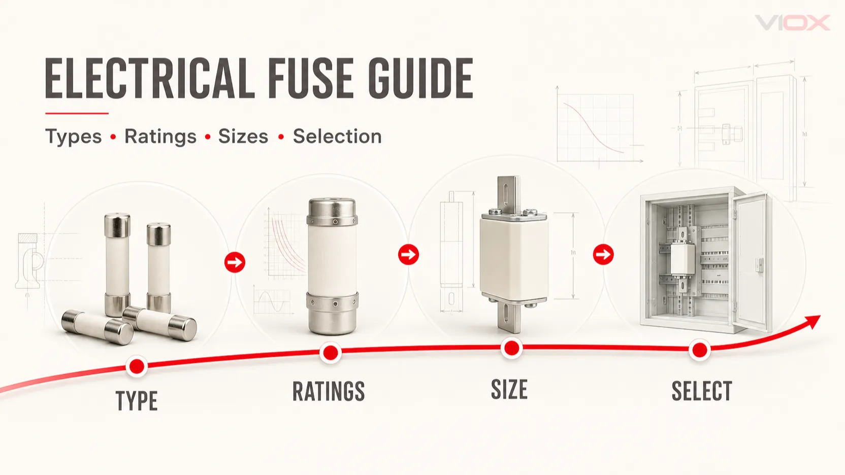
Choosing a fuse requires more than matching its ampere rating. The correct device must have the right voltage rating, AC or DC rating, breaking capacity, time-current characteristic, application class, physical format and compatible fuse holder. The final choice should always be checked against the product datasheet, the protected equipment requirements and the applicable installation rules.
Fuse Selection at a Glance
| Selection question | Specification to check | Why it matters |
|---|---|---|
| What is being protected? | Cable, motor, transformer, semiconductor, PV string, battery or electronic circuit | Determines the fuse family and operating characteristic |
| What current flows normally? | Rated current and actual load profile | The fuse must carry normal current without nuisance opening while still protecting the circuit |
| Is there startup or inrush current? | Time-current curve and pre-arcing I²t | Motors, transformers, capacitors and power supplies can draw high current temporarily |
| What is the maximum circuit voltage? | Rated voltage and AC/DC designation | The fuse must safely interrupt the circuit at the actual voltage |
| What fault current is available? | Breaking capacity or interrupting rating | The rating must be at least equal to the prospective short-circuit current at the installation point |
| What must be protected from fault energy? | Total clearing I²t and peak let-through current | Important for semiconductors, conductors and coordinated protection |
| Where will the fuse be installed? | Size, mounting format, holder rating and power dissipation | A physically fitting fuse is not necessarily electrically compatible |
| Which market or equipment standard applies? | IEC, UL/CSA or application-specific evidence | Current-rating conventions and permitted fuse classes can differ |
This table is a shortlisting tool, not a substitute for a coordination study or manufacturer verification.
How Does an Electrical Fuse Work?
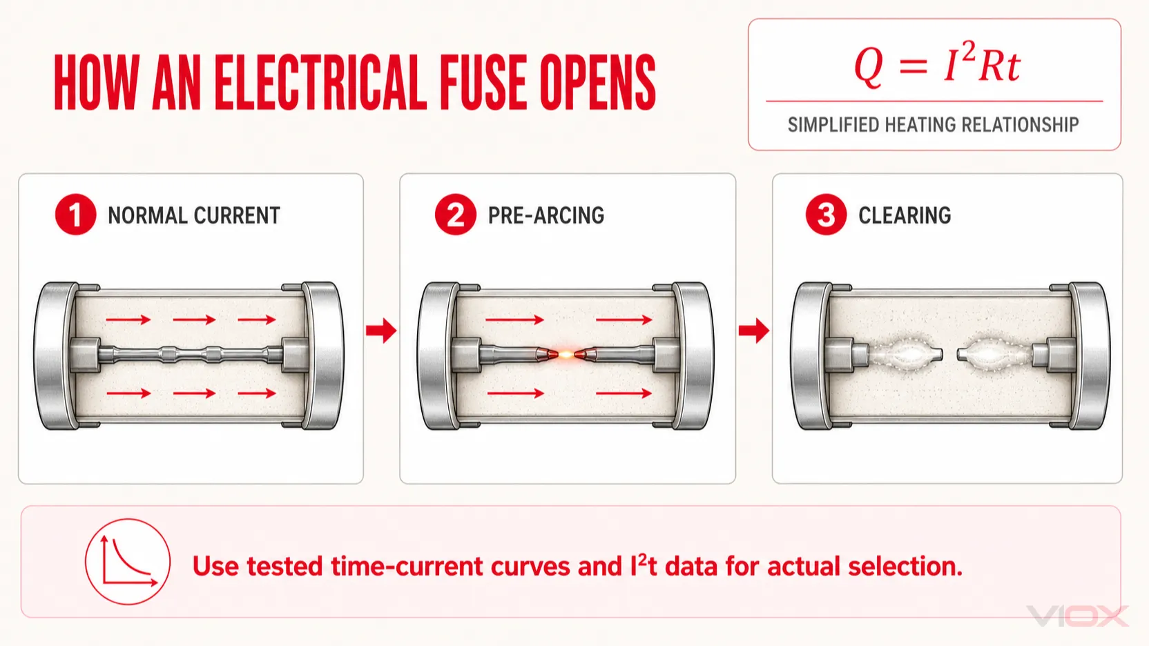
A fuse operates through the heating effect of current. A simplified relationship is:
Q = I²Rtwhere Q is heat, I is current, R is the resistance of the element and t is time. Because current is squared, a large fault current can heat the fuse element much more rapidly than a modest overload.
This is a simplified heating relationship, not a standalone fuse-sizing equation. During fuse operation, element resistance changes with temperature, material state and effective cross-section. Actual pre-arcing and clearing behavior must therefore be determined from the tested time-current curves, I²t data and other manufacturer information for the exact fuse series.
Fuse operation has two main intervals:
- Pre-arcing or melting time: the element heats and separates.
- Arcing time: an arc forms across the opening element and is extinguished by the fuse construction.
The total clearing time is the sum of these intervals. It is not one fixed number for all fuses. It depends on the fuse design, the magnitude of the overcurrent, circuit voltage, AC or DC duty and other test conditions. Use the time-current curve and clearing data for the exact fuse series instead of assuming every fuse operates in a few milliseconds.
Many industrial cartridge fuses use a ceramic body and granular filler to contain and cool the arc. Current-limiting designs can interrupt a high fault before the prospective current reaches its unrestricted peak, reducing the energy passed to downstream equipment.
Main Types of Electrical Fuses
Fuse types are commonly classified by construction, application and operating characteristic. These classifications overlap: for example, a cylindrical cartridge fuse may also be a gG, gPV or semiconductor fuse.
| Fuse family | Typical construction or format | Common applications | Main selection focus |
|---|---|---|---|
| Miniature cartridge fuse | Glass or ceramic tube, often 5 × 20 mm or 6.3 × 32 mm | Electronic equipment, instruments, control circuits and appliances | Voltage, breaking capacity, fast/time-delay behavior and holder fit |
| Industrial cylindrical fuse | Ceramic cartridge, commonly 10 × 38, 14 × 51 or 22 × 58 mm | Control panels, distribution circuits, motors and PV systems | IEC utilization category, AC/DC rating, breaking capacity and holder compatibility |
| NH knife-blade fuse | Rectangular ceramic body with blade contacts | Industrial distribution, feeders, motor circuits and switch-fuse assemblies | NH size, utilization category, holder, breaking capacity and safe handling method |
| D/D0 fuse | Bottle-shaped fuse link used with a screw base | Distribution systems in markets using DIAZED or NEOZED formats | System format, gauge arrangement, voltage and application category |
| Automotive blade fuse | Plug-in blade body | Vehicle and low-voltage mobile circuits | Vehicle standard, voltage, current, blade format and holder |
| Semiconductor fuse | High-speed cartridge, blade or bolted format | Drives, rectifiers, inverters, UPS and power electronics | Total clearing I²t, peak let-through current and device coordination |
| PV fuse | DC-rated gPV or other PV-specific construction | Photovoltaic strings, arrays and combiner boxes | Maximum DC voltage, string fault current, temperature, holder and PV requirements |
| Battery/EV fuse | Bolted, cartridge or other high-energy DC format | Battery energy storage and electric vehicles | DC fault profile, voltage, time constant, breaking capacity and system validation |
| Rewirable fuse | Replaceable fuse wire in a carrier | Legacy installations in some markets | Correct wire and installation rules; not interchangeable with modern cartridge systems |
For a deeper explanation of ceramic high-fault designs, see What Is an HRC Fuse?. For the differences between the two most common industrial formats, see NH Fuse vs Cylindrical Fuse.
Cartridge Fuse Size Chart
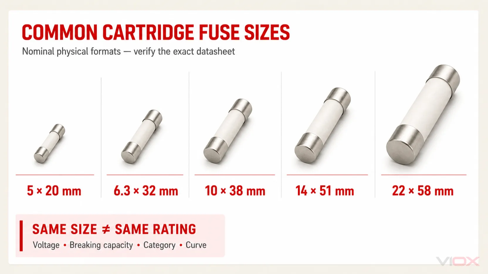
The dimensions below identify common physical formats. They do not define a fuse’s current, voltage, breaking capacity or operating curve. Two fuses with the same dimensions may have different electrical ratings and may not be interchangeable.
| Nominal cartridge size | Alternative size description | Common context | What to verify before replacement |
|---|---|---|---|
| 5 × 20 mm | Metric miniature cartridge | Electronics, instruments and small control circuits | Fast or time-delay marking, voltage, breaking capacity, approvals and holder rating |
| 6.3 × 32 mm | Approximately 1/4 × 1-1/4 in; often called 3AG/AGC format in relevant families | North American-style equipment, instruments and control circuits | Exact series, AC/DC rating, interrupting rating and terminal/holder format |
| 10 × 38 mm | Industrial cylindrical cartridge | Distribution, control, motor and PV applications | Utilization category, DC or AC rating and compatible modular holder |
| 14 × 51 mm | Industrial cylindrical cartridge | Higher-current industrial circuits | Holder power dissipation, utilization category and breaking capacity |
| 22 × 58 mm | Industrial cylindrical cartridge | Industrial distribution and higher-current applications | Touch-safe holder or switch-disconnector compatibility and operating conditions |
Size labels are nominal. Consult the exact outline drawing for body dimensions, cap dimensions and tolerances. Never force a cartridge into an incompatible clip or holder, and never assume that physical fit proves electrical compatibility.
Even when products from different manufacturers have the same external dimensions, their rated voltage, breaking capacity, utilization category, time-current characteristic and power dissipation may differ. Treat them as interchangeable only after the complete specifications and holder compatibility have been verified.
NH fuses use size designations such as NH000, NH00, NH0, NH1, NH2 and NH3 rather than a simple diameter-by-length label. The complete fuse link, base or switch-disconnector, handle provisions and permitted power dissipation must be matched as a system.
Fuse Ratings and Markings Explained
Rated Current
Rated current is defined under specified test conditions. It does not mean that every fuse can carry the marked current indefinitely in every enclosure and ambient temperature.
Current selection should consider:
- maximum continuous load current
- load tolerance and expected operating profile
- startup, transformer magnetizing or capacitor-charging inrush
- ambient temperature and enclosure heating
- terminal and holder temperature rise
- cable ampacity and equipment protection requirements
- differences between the applicable IEC and UL fuse conventions
A fixed multiplier such as 125% is not a universal fuse-sizing rule. Some device families use manufacturer rerating guidance, while installation rules may impose separate conductor or equipment protection limits. Start with the actual operating current, then apply the method required by the fuse manufacturer and the applicable code or equipment standard.
Rated Voltage
The fuse voltage rating must be equal to or higher than the maximum voltage the fuse may have to interrupt. Confirm whether the rating applies to AC, DC or both.
Voltage rating is primarily about safe interruption after the element melts. A fuse may open the element but fail to clear the circuit safely if its voltage rating or DC capability is inadequate. This is especially important in PV, battery and other DC systems because the arc does not benefit from the natural current zero that occurs in an AC waveform.
Read more in AC Fuse vs DC Fuse.
Breaking Capacity or Interrupting Rating
Breaking capacity is the maximum prospective current a fuse can safely interrupt at a stated voltage and under specified conditions.
The essential check is:
Fuse breaking capacity ≥ prospective short-circuit current at the installation pointThe available fault current depends on the source, transformer impedance, conductors and circuit layout. Do not assign a generic residential, commercial or industrial fault-current value without a calculation or verified system data.
For PV systems, see DC Fuse Breaking Capacity for PV Systems.
Time-Current Characteristic
A time-current curve shows how the fuse’s pre-arcing or operating time changes with current. Fuses with the same current rating can have very different curves.
Use the curve to confirm that the fuse:
- carries normal load current;
- tolerates permitted startup or inrush events;
- opens within the time required to protect the cable or equipment;
- coordinates with upstream and downstream protective devices.
Terms such as fast-acting, time-delay and high-speed are useful only when connected to the exact fuse family and its datasheet. They should not be converted into one universal response-time table.
I²t and Peak Let-Through Current
I²t expresses the current-squared energy associated with a defined portion of fuse operation.
- Pre-arcing or melting I²t describes the energy required to melt the element.
- Arcing I²t describes energy during the arc interval.
- Total clearing I²t combines melting and arcing energy.
For a load with inrush, the fuse’s pulse withstand must be checked against the inrush waveform. For semiconductor protection, the fuse’s total clearing data must be coordinated with the device’s withstand data under compatible conditions.
There is no universal rule that the downstream I²t must always be a fixed percentage of the upstream I²t. Selectivity depends on the tested fuse pair, fault-current range, manufacturer coordination tables and the complete time-current characteristics.
For a focused speed comparison, see Fuse vs MCB Response Time.
Utilization Category
Under IEC-oriented fuse systems, the utilization category describes the current range the fuse can interrupt and the application it is intended to protect.
| Category | General role | Important boundary |
|---|---|---|
| gG | Full-range general-purpose protection, commonly for cables and distribution circuits | Confirm the exact cable and coordination requirements |
| aM | Partial-range short-circuit protection for motor circuits | Requires separate overload protection |
| aR | Partial-range semiconductor protection | Must be coordinated with the semiconductor and does not replace all circuit protection functions |
| gR | Full-range semiconductor protection | Verify device-specific I²t and time-current data |
| gPV | Full-range PV fuse link for photovoltaic array protection | Requires PV-specific DC selection and installation checks |
For categories such as aR and gR, procurement teams must verify the applicable part of the IEC 60269 series, the exact manufacturer datasheet and model-specific certificate or test evidence. A category printed on a product webpage is not sufficient evidence of conformity or application suitability.
For a standards-focused explanation, use the IEC 60269 Fuse Guide: gG vs aM, NH Sizes and Selection.
How to Select the Correct Electrical Fuse
Step 1: Define the Protection Objective
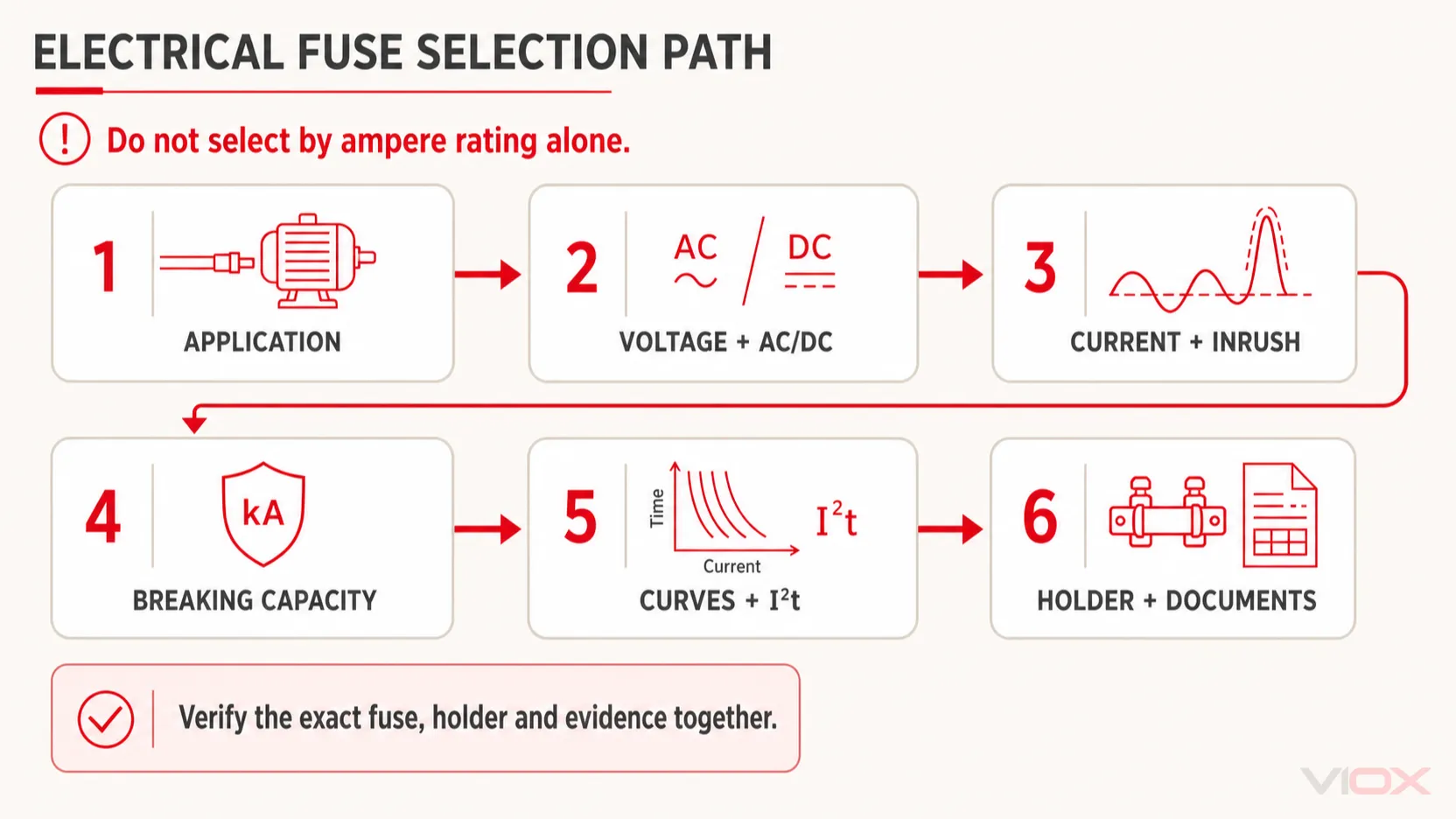
State what must be protected and from which conditions. A fuse selected to protect a cable may differ from one intended to protect a motor branch, semiconductor module or PV string.
Record:
- load and conductor details
- normal and maximum operating current
- overloads that must be tolerated or interrupted
- startup or inrush waveform
- maximum system voltage and AC/DC duty
- prospective short-circuit current
- permitted let-through energy or clearing time
- ambient and enclosure conditions
- required standard, market approval and holder format
Step 2: Choose the Application Class and Physical Family
Select the broad fuse family before selecting the ampere rating. Examples include gG cylindrical for a distribution circuit, aM with separate overload protection for a motor, high-speed semiconductor fuse for a power converter or gPV for a PV string.
Then choose a format supported by the installation: miniature cartridge, 10 × 38 cylindrical, NH, bolted high-speed fuse or another specified system.
Step 3: Verify Voltage and AC/DC Capability
Confirm the fuse rating at the maximum operating voltage, including expected tolerances. Do not use an AC-only rating as evidence of DC interruption capability.
For PV and battery circuits, verify the applicable DC rating, fault-current test conditions, circuit time constant where relevant and the manufacturer’s installation requirements.
Step 4: Determine a Candidate Current Rating
Use the maximum continuous current and load profile to shortlist a current rating. Apply manufacturer rerating guidance for ambient temperature, enclosure, cooling, repetitive pulses and mounting conditions.
The candidate must also satisfy conductor and equipment protection requirements. Increasing the current rating to stop nuisance opening can leave the protected circuit inadequately protected; first determine whether the cause is inrush, excess ambient temperature, a loose holder connection or a real overload.
Step 5: Check Inrush Against the Time-Current Curve and I²t Data
Plot or compare the actual startup event against the fuse curve. For short pulses, use the manufacturer’s pulse and I²t method. Repetitive pulses require additional margin because thermal cycling can affect fuse life.
For motors, confirm starting current, starting duration and overload protection. For transformers and power supplies, check magnetizing or capacitor-charging inrush rather than assuming a standard multiplier.
Step 6: Verify Breaking Capacity
Obtain or calculate the prospective short-circuit current at the fuse location. Confirm that the fuse’s breaking capacity is equal to or greater than that value at the applicable voltage and current type.
Step 7: Check Coordination and Let-Through Energy
Compare the exact fuse curves and manufacturer selectivity data with upstream and downstream devices. If protecting a semiconductor, compare total clearing I²t and peak let-through current with the device limits using compatible test conditions.
Step 8: Match the Fuse Holder and Installation
Confirm:
- fuse dimensions and contact format
- holder current and voltage ratings
- permitted fuse power dissipation
- wire and terminal capacity
- touch protection and isolation needs
- suitability for switching under load
- enclosure temperature, pollution and ventilation conditions
- required replacement tool or safe handling method
A fuse holder is not automatically a load-break switch. If the installation must be operated under load, use appropriately rated equipment. See Fuse Holder vs Fuse Switch Disconnector.
Step 9: Verify Documentation and Validate the Application Safely
Review the exact datasheet, time-current curves, temperature rerating information, approval evidence and holder documentation. Where the fuse protects equipment or must withstand repetitive pulses, validate the selection using approved test procedures, laboratory or manufacturer testing, protection-coordination calculations and verified time-current data.
Do not deliberately create a fault in an energized field installation to validate a fuse. Any physical fault testing must be performed only in a suitably equipped test environment by qualified personnel under an approved procedure.
Fuse Selection by Application
| Application | Likely starting point | Required next check | Detailed VIOX guide |
|---|---|---|---|
| General cable or feeder protection | Full-range general-purpose fuse such as gG in an IEC system | Cable protection, fault level and selectivity | IEC 60269 Low-Voltage Fuse Selection |
| Motor branch circuit | aM or another motor-suitable fuse arrangement | Separate overload protection, starting current and coordination | MCB vs Fuse for Motor Circuits |
| Power semiconductor | High-speed semiconductor fuse | Device total clearing I²t, peak current and voltage | Fuse vs MCB Response Time |
| PV string or combiner box | DC-rated gPV fuse where overcurrent protection is required | String count, reverse current, maximum voltage, temperature and holder | How to Properly Fuse a Solar PV System |
| 12 V vehicle or auxiliary system | Automotive blade or appropriate low-voltage fuse | Wire ampacity, source fault current, holder and vehicle standard | How to Choose Fuse Size for a 12 V System |
| Industrial panel requiring service isolation | Fuse plus correctly rated holder/base or fuse switch disconnector | Load-break duty, interlocking, safe replacement and coordination | Fuse Holder vs Fuse Switch Disconnector |
Electrical Fuse vs Circuit Breaker
Fuses and circuit breakers both provide overcurrent protection, but neither is universally better.
| Decision factor | Fuse | Circuit breaker |
|---|---|---|
| Operation after a fault | Fuse link must be replaced | Can usually be reset after the fault is investigated and the device is confirmed serviceable |
| Current limitation | Strong current limitation is available in suitable fuse designs | Depends on breaker type, rating and current-limiting classification |
| Adjustment | Fixed characteristic | Some breakers provide adjustable protection settings |
| Switching and remote functions | Requires an appropriate switch-fuse or switching device | Switching, auxiliaries and remote operation may be available |
| Replacement control | Correct replacement fuse must be available and installed | Reset avoids replacement but can encourage reset without diagnosing the fault |
| Coordination | Based on fuse curves and tested selectivity data | Based on trip curves, settings and manufacturer coordination data |
Do not compare all fuses with all breakers using fixed response time, price or arc-flash values. Performance depends on the exact devices and system fault conditions. For the complete decision, see Fuse vs Circuit Breaker: Key Differences and Applications.
Common Fuse Selection Mistakes
| Mistake | Why it is risky | Better practice |
|---|---|---|
| Selecting only by ampere rating | Ignores voltage, breaking capacity, curve and application | Build a complete fuse specification |
| Assuming the same physical size means interchangeability | Same-size fuses can have different curves and interruption capability | Match the exact series or verify every relevant parameter |
| Replacing a fuse with a higher rating after repeated operation | Can leave cable or equipment unprotected | Diagnose overload, inrush, temperature and connection conditions |
| Using an AC-rated fuse in a DC application without a DC rating | The arc may not be interrupted safely | Verify the marked DC voltage and breaking capacity |
| Ignoring prospective short-circuit current | The fuse body can rupture if fault duty exceeds its rating | Calculate or obtain the available fault current |
| Treating aM as complete motor protection | aM is a partial-range fuse category | Coordinate it with separate overload protection |
| Ignoring holder power dissipation and contact condition | Excess heat can develop at the holder rather than in the fuse element | Match the holder and inspect connection quality |
| Using a generic temperature derating percentage | Fuse families respond differently to temperature | Use the exact manufacturer derating curve |
Electrical Fuse Standards: What to Check
The applicable standard depends on fuse family, equipment type and market.
- IEC 60269 covers specified low-voltage fuse systems. The current IEC 60269-1:2024 scope includes enclosed current-limiting fuse links with rated breaking capacity of at least 6 kA for power-frequency AC circuits up to 1,000 V or DC circuits up to 1,500 V. Subsequent parts add requirements for particular users and applications.
- IEC 60127 addresses miniature fuses used for the protection of electronic equipment and related applications.
- UL 248 is the U.S. fuse standard series, while UL 4248 addresses fuse holders. UL Solutions lists these scopes in its fuse and fuseholder services.
Do not write “IEC compliant,” “UL listed” or “CE certified” for a product family without model-specific evidence. Ask for the certificate, test report or listing information covering the exact fuse and holder being supplied.
Frequently Asked Questions
What are the main types of electrical fuses?
Common types include miniature glass or ceramic cartridge fuses, industrial cylindrical fuses, NH knife-blade fuses, D/D0 fuses, automotive blade fuses, semiconductor fuses, PV fuses and battery/EV fuses. The best classification depends on whether you are comparing construction, physical format, application or operating characteristic.
What do the numbers on a fuse mean?
Markings commonly identify rated current and voltage. A fuse may also show speed, breaking-capacity class, utilization category, approval marks and a manufacturer series code. Interpret the marking using the exact datasheet because abbreviations differ among IEC, UL and manufacturer systems.
Can I replace a 5 × 20 mm fuse with any other 5 × 20 mm fuse?
No. Physical size alone is insufficient. Match current, voltage, AC/DC duty, fast or time-delay characteristic, breaking capacity, approvals and holder requirements.
Is a 250 V fuse suitable for a 12 V circuit?
It may be suitable from a voltage-ceiling perspective, but only if the fuse has the required DC interruption capability, current rating, breaking capacity, time-current behavior and application approval. Low-voltage circuits with batteries can still have very high available fault current.
What is the difference between fast-acting and time-delay fuses?
Fast-acting fuses are designed to respond more quickly to specified overcurrents, while time-delay fuses tolerate defined temporary inrush events. The actual opening time depends on the current multiple and the exact time-current curve; the label alone is not enough for coordination.
How do I calculate the correct fuse current?
There is no single multiplier for every fuse and application. Start with maximum continuous current, load tolerance, startup or pulse behavior, ambient conditions, conductor protection and the equipment standard. Then apply the exact fuse manufacturer’s rerating and time-current data.
Why does a correctly rated fuse keep opening?
Possible causes include a real overload, startup inrush, repetitive pulses, high ambient temperature, poor holder contact, undersized conductors, equipment failure or an incorrectly selected time-current characteristic. Diagnose the circuit before increasing the fuse rating.
Does a fuse protect against overvoltage?
No. A fuse protects against overcurrent. Surge protective devices address transient overvoltage, while other equipment may be required for sustained overvoltage or undervoltage conditions.
Specify the Fuse Before Requesting a Product
Before comparing products, prepare these application details:
- maximum AC or DC voltage
- continuous current and load profile
- startup or inrush current and duration
- prospective short-circuit current
- required fuse category or protected equipment
- cartridge or blade format and holder
- ambient and enclosure conditions
- applicable standard and required approval evidence
You can then review VIOX low-voltage fuses and fuse holders or submit the application parameters for model-level selection support.