On this page
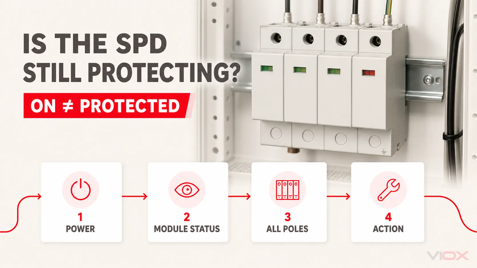
An industrial surge protective device (SPD) can be connected to an energized panel even after one protection module has disconnected. Load power therefore does not prove that surge protection is available. Read every model-defined status window, light, display, or alarm and compare it with the instructions for the exact device.
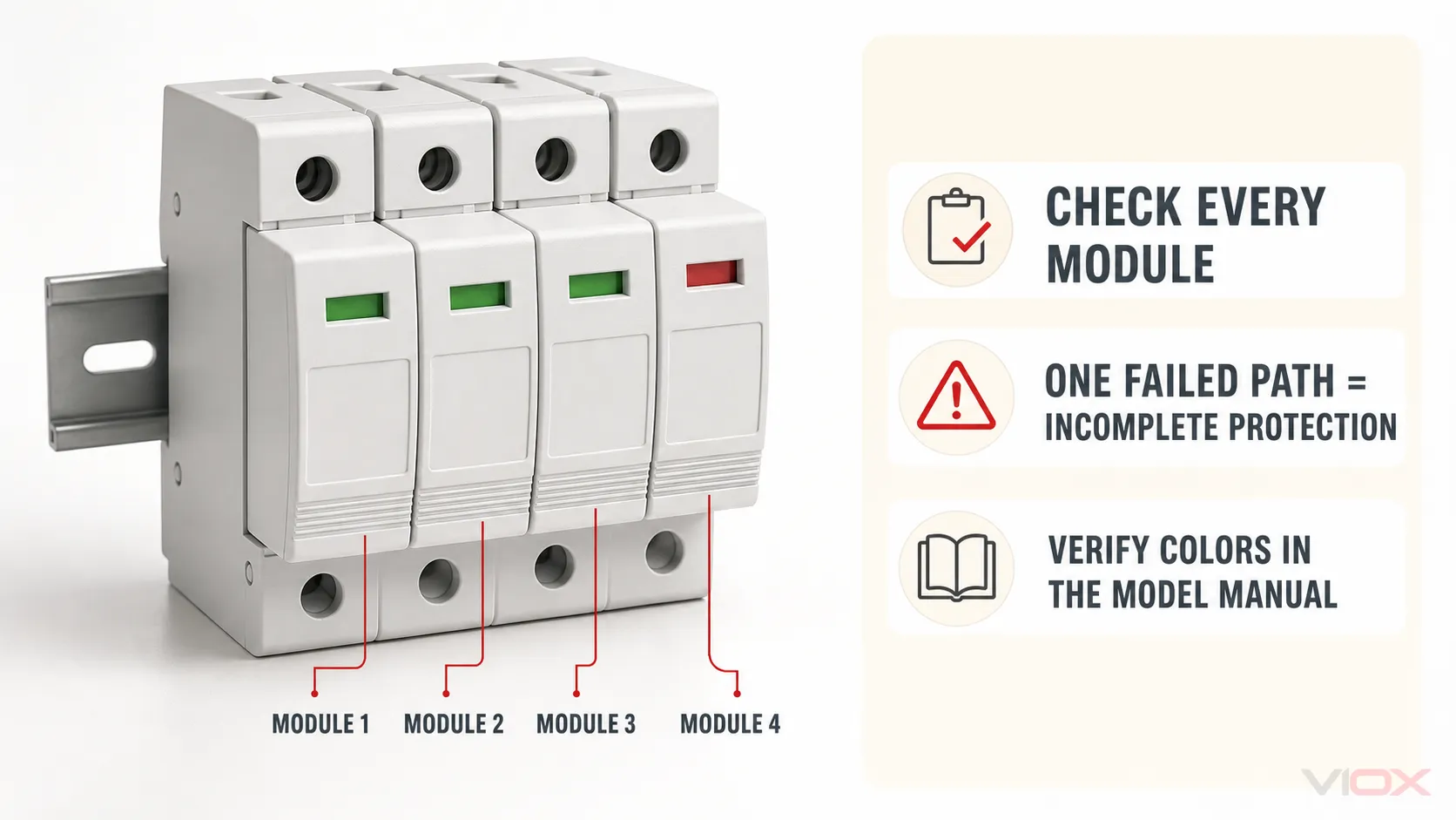
Green commonly means that a modular SPD remains available, while red commonly means that an internal disconnector has operated and the affected module requires replacement. Those meanings are not a universal color code. Some indicators are mechanical windows rather than lights, some products use different colors or symbols, and some report only an aggregate state. If one pole or protection mode shows failure, complete intended protection is no longer confirmed.
Key Takeaways
- “On” is ambiguous. It can mean the panel is energized, the load is operating, an SPD module reports available, or the complete installation has been verified. These are different conditions.
- Check every module. One normal window does not cancel one failed window in a multi-pole SPD.
- Use the exact model instructions. Color, contact logic, replaceable scope, and reset behavior vary.
- A normal indicator has limits. It does not prove correct supply voltage, wiring, earthing, backup protection, conductor routing, or full remaining surge capacity.
- Do not use an ordinary multimeter as a remaining-life test. It cannot reproduce the impulse tests used to characterize an SPD.
- Treat damage and abnormal heating as stop conditions. Do not wait for a status window to change before escalating a visibly damaged assembly.
The Four Statuses Hidden Inside the Word “On”
The fastest way to avoid a false conclusion is to separate four questions.
| Status question | Evidence that answers it | What it does not establish |
|---|---|---|
| Is the electrical system energized? | Approved voltage-presence procedure performed by qualified personnel, panel instruments, or system status | That the SPD is connected correctly or still protective |
| Does each SPD module report available? | Exact model’s local window, LED, display, or diagnostic output | Remaining surge capacity, correct application, or complete system protection |
| Are all intended poles or protection modes available? | Every required module indication plus the device’s aggregate or remote status where provided | Earthing quality, conductor routing, backup protection, or coordination |
| Is the installed protection system verified? | Design and installation evidence, model instructions, inspection, protective-device checks, and applicable verification process | Future performance against every possible event |
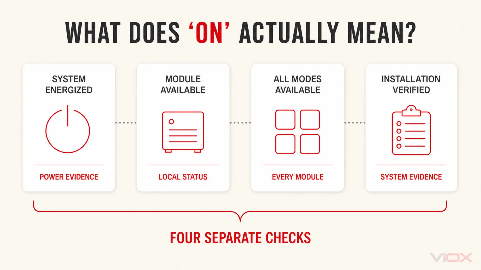
An industrial panel can satisfy the first question while failing the second or third. A green local window can satisfy part of the second question while leaving the fourth unanswered.
For the broader product boundary, see what a surge protective device does. This page concentrates only on interpreting the current status and deciding the next action.
Industrial SPD Status: Symptom, Meaning, and Action
Start with the device label and manual, then use the observed state as a diagnostic input—not as a universal verdict.
| Observed condition | Safe check | Likely interpretation | Next action |
|---|---|---|---|
| Every required module shows the model-defined normal state | Confirm the indicator meaning and identify every required pole or mode | The monitoring or disconnector mechanism reports the modules available | Continue monitoring if there is no damage, alarm, significant-event instruction, or application concern |
| One module shows the model-defined failed or replace state | Identify the affected pole or protection mode; compare local and remote status | The affected protection path may have been disconnected or declared unavailable | Treat complete protection as unavailable; follow the replacement and investigation instructions |
| Several modules change state together | Record which modules changed and whether a common event, breaker operation, or supply abnormality occurred | A common surge, temporary overvoltage (TOV), wiring problem, or other shared stress may be involved | Inspect the complete SPD assembly and system before restoring confidence; do not replace cartridges blindly |
| Local indication and remote contact disagree | Confirm the contact’s normal/alarm truth table, control power, terminal continuity where permitted, and local state | The signaling circuit, contact interpretation, module seating, or monitoring path may be faulty | Escalate the discrepancy; do not let an unverified BMS “normal” override a local failed state |
| No local status feature is present | Identify the exact model and documented diagnostic method | Condition cannot be inferred from enclosure appearance or load operation | Use the manufacturer-approved method or adopt a conservative replacement decision for a critical application |
| Indicator appears normal after a known severe event | Review the manual’s post-event instructions, event records, physical condition, and system alarms | A binary indicator may show only that its monitored disconnector has not operated | Keep, verify, or replace according to documented post-event criteria and asset criticality |
| Burn marks, odor, cracked housing, contamination, loose plug, or abnormal heat is present | Make the panel safe under the site procedure and inspect the assembly and adjacent equipment | Physical, thermal, mechanical, or environmental damage may exist beyond the monitored element | Remove the affected equipment from service and investigate the initiating condition |
| A replacement module soon reports failure again | Check system voltage, Uc or MCOV selection, TOV exposure, protection mode, earthing arrangement, backup protection, and installation | Repeated misapplication or abnormal system stress is more likely than ordinary calendar aging | Stop repeated like-for-like replacement until the root cause is identified |
This matrix deliberately separates a reported state from a complete engineering diagnosis. A status mechanism is valuable because it makes a hidden failure observable; it does not identify every possible root cause.
Why the Protected Equipment May Keep Running After SPD Failure
Most panel-mounted power SPDs are connected in parallel with the supply rather than placed in series with the load. During normal operation, the SPD does not carry the load current. It responds to transient overvoltage according to its design and protection modes.
If an internal disconnector removes a failed protection element from the circuit, the branch or bus supplying the protected equipment may remain energized. The machinery, PLC, drive, server, or other load can therefore operate normally while one surge-protection path is unavailable.
That creates the central diagnostic rule:
Load operating = power is available to the load. It does not equal SPD protection available.
The opposite also needs care. A de-energized load does not prove that an SPD failed. The cause could be an upstream protective device, control action, supply loss, wiring fault, or another system condition. Interpret SPD status separately from load status.
How to Read a Modular SPD Status Window
1. Identify whether it is a window, LED, display, or symbol
A colored rectangle on a plug-in cartridge may be a mechanically actuated status window, not an illuminated lamp. Other models use LEDs, alphanumeric displays, audible alarms, or a remote changeover contact. Call it a status indicator until the documentation identifies the technology.
This wording matters because “the light is off” has no meaning when the device uses a mechanical flag. It also prevents an installer from assuming that an unlit feature proves the panel is de-energized.
2. Confirm the model-defined normal and failed states
Green/red indication is common in modular power SPDs. Phoenix Contact, for example, publishes products with replaceable surge-protection plugs, local green/red indication, thermal monitoring, and optional remote signaling. That is evidence for those product families, not a universal rule for every SPD.
Use the exact product label, datasheet, and installation instructions to confirm:
- which color, symbol, or position means available;
- whether the indication belongs to one cartridge or the whole assembly;
- whether an intermediate warning state exists;
- whether the device is resettable or requires replacement;
- whether the cartridge, base, or complete assembly is the replaceable scope;
- how the remote contact behaves in normal, alarm, de-energized, and removed-module states.
3. Read every required pole or protection mode
A three-phase SPD may have several local windows. Record each state individually. If three windows show normal and one shows failed, do not describe the SPD as “mostly working.” The intended protection arrangement is incomplete until the affected path is restored and the retained assembly is accepted under the manufacturer’s instructions.
The labels on the device and its topology documentation determine which phase, neutral, or protection mode corresponds to each module. Similar enclosure geometry is not enough to infer the circuit.
4. Compare local and remote status
An optional floating changeover contact can send an aggregate state to a programmable logic controller (PLC), building management system (BMS), or supervisory control and data acquisition (SCADA) system. It can shorten the time between a declared failure and maintenance response.
The contact does not automatically reveal the failed pole, surge magnitude, cause, remaining capacity, or installation correctness. Contact logic is also model-specific. Use the exact terminal diagram and truth table; the dedicated guide to SPD remote signaling covers that separate monitoring task.
What a Green Indicator Can—and Cannot—Tell You
When the exact product documentation defines green as normal or OK, the strongest safe statement is:
The monitored module remains in the model-defined available state.
Do not expand that into “the complete surge-protection system is perfect.” A normal local indication generally cannot prove all of the following:
- that supply voltage is present at the SPD terminals;
- that the selected Uc or maximum continuous operating voltage is correct for the system;
- that line, neutral, and protective-earth conductors are connected correctly;
- that the earthing and bonding paths are effective;
- that the required backup fuse or circuit breaker is correct and available;
- that connection conductors are short and routed as required;
- that upstream and downstream SPDs are coordinated;
- that every conductive power, signal, data, or antenna path is protected;
- that the MOV or other nonlinear element retains its original surge capability;
- that the installation will withstand every future transient event.
Industrial status windows are usually condition declarations with a defined monitoring boundary, not laboratory instruments. The exact SPD datasheet and installation record remain necessary.
What a Red Indicator Usually Requires
When the exact manual defines red as failed, replace, or end of life, treat the affected protection path as unavailable. The common action sequence is:
- Record the evidence. Photograph every status window, note remote alarms, identify the model and cartridge, and record any recent surge, utility, generator, switching, or TOV event.
- Apply the approved safety procedure. Opening a distribution panel or removing a cartridge can expose workers to energized conductors and arc-flash hazards. Qualified personnel must follow site isolation, lockout/tagout, verification, personal-protective-equipment, and local electrical-safety requirements.
- Inspect the replacement scope. Check the base, plug contacts, terminals, enclosure, remote contact, backup protection, and adjacent equipment as the manufacturer requires.
- Identify the cause when failure is premature, repeated, multi-pole, or physically abnormal. Verify application voltage, Uc or MCOV, TOV behavior, topology, earthing system, protection mode, backup protection, and installation.
- Install only an approved compatible replacement. Matching shape or color is not proof of electrical, mechanical, or signaling compatibility.
- Verify restoration. Confirm every local state, the remote alarm truth table, module seating, protective-device status, and maintenance record after safe re-energization.
A plug-in cartridge must not be assumed to be hot-swappable simply because it can be removed without disconnecting conductors from the base.
Replace One Cartridge or the Complete SPD?
| Condition | A cartridge-only replacement may be acceptable when… | Replace or escalate beyond one cartridge when… |
|---|---|---|
| One module reports end of life | The manufacturer permits individual replacement, the exact approved cartridge is available, and the base passes inspection | The SPD is non-modular, compatibility is uncertain, or the base and contacts show damage |
| Several modules fail after one event | Every retained part passes the documented inspection and the manufacturer permits selective replacement | A common event may have affected the base, insulation, remote contact, several modes, or coordinated protection system |
| Remote contact disagrees with local indication | The signaling fault is separately identified and corrected without uncertainty about protection status | The monitoring architecture cannot establish a trustworthy normal state |
| A replacement fails again | The first failure cause was identified and corrected and the retained assembly remains acceptable | Voltage selection, TOV, wiring, environment, or coordination remains unresolved |
| Product is obsolete | A documented manufacturer-approved replacement plug exists | No exact compatibility evidence is available or the current base is no longer supportable |
Detailed MOV degradation and condition-based service-life decisions belong in the industrial SPD lifespan guide. This page uses the current status only to decide the immediate action.
Can You Test an SPD With a Multimeter?
An ordinary multimeter cannot prove the remaining impulse performance of an installed SPD. A simple resistance, continuity, or AC-voltage reading does not reproduce the standardized surge waveforms, currents, protection levels, thermal behavior, disconnector operation, or multi-mode interactions used to characterize the device.
A meter may support a manufacturer-authorized check of an isolated auxiliary contact, continuity path, or other specifically documented function. That is not the same as proving that the complete SPD still meets its original surge-performance declarations.
Do not probe an energized distribution panel merely to answer a generic internet test. Test points, isolation, instrument category, personal protective equipment, and procedure must all match the installation and be handled by qualified personnel. For the narrower boundary of pre-installation checks, see what a multimeter can and cannot verify on a DC SPD.
Plug-In Surge Protector Lights: A Short Consumer Branch
The same “on versus protected” distinction applies to consumer plug-in surge protectors, but their indicators and load path differ from panel SPDs.
| Plug-in indication | What it may mean | Correct interpretation rule |
|---|---|---|
| Power or switch light | The strip’s outlets may be energized | Does not prove the surge-protection circuit remains available |
| Protected or Protection light | Model-defined status of the surge-protection function | Follow the exact label and manual; replace when the documentation says protection is lost |
| Grounded, Earthed, or Wiring Fault light | A model-defined supply-wiring condition | Not the same as an SPD end-of-life indication; have the wiring condition assessed as instructed |
| No separate protection indicator | No user-visible confirmation of protection status | Load operation alone cannot close the uncertainty |
Do not apply an industrial green/red cartridge rule to every consumer strip. If the first question is whether a strip contains surge protection at all, use the power strip vs surge protector guide. For replacement timing and physical warning signs, use the dedicated consumer surge-protector lifespan guide.
Frequently Asked Questions
Does a green SPD indicator prove the SPD is working?
It proves only the state defined by the exact product documentation. On many modular products, green means the monitored module remains available. It does not prove correct voltage selection, wiring, earthing, backup protection, coordination, or full remaining surge capacity.
What does one red module on a three-phase SPD mean?
If the manual defines red as failed or replace, the affected pole or protection mode is unavailable and complete intended protection is no longer confirmed. Record every module state and follow the manufacturer’s replacement and inspection instructions.
Can protected equipment keep running when an SPD has failed?
Yes. A panel SPD is commonly connected in parallel with the load. An internal disconnector can remove a failed protection element while the distribution circuit and protected equipment remain energized.
Can a red SPD cartridge be reset?
Usually a model-defined end-of-life state associated with an operated internal disconnector requires replacement, not reset. Confirm the exact product instructions and never bypass a sealed protective module or its disconnector.
Should all SPD cartridges be replaced when one turns red?
Not automatically. Selective replacement depends on the assembly design, event, base condition, protection modes, exact cartridge compatibility, and manufacturer instructions. Multi-pole failure, physical damage, repeated failure, or uncertainty can require replacing a wider scope.
Can an ordinary multimeter confirm that an SPD is still good?
No. It cannot reproduce standardized impulse performance or quantify the remaining capability of the complete SPD. Use the model’s documented status and diagnostics, and escalate uncertain or critical conditions.
What if the indicator remains green after a major surge?
Check the manufacturer’s post-event instructions, physical condition, event records, remote alarms, and asset criticality. A green binary state may show only that the monitored disconnector has not operated; it does not measure how much surge capability remains.
Final Decision Rule
Do not call an industrial SPD “on” merely because the panel or load has power. Determine four states separately:
- Is the system energized under an approved verification method?
- Does every required SPD module report the model-defined available state?
- Are all intended poles or protection modes available, with local and remote states consistent?
- Does the installation evidence support correct application, wiring, earthing, backup protection, and condition?
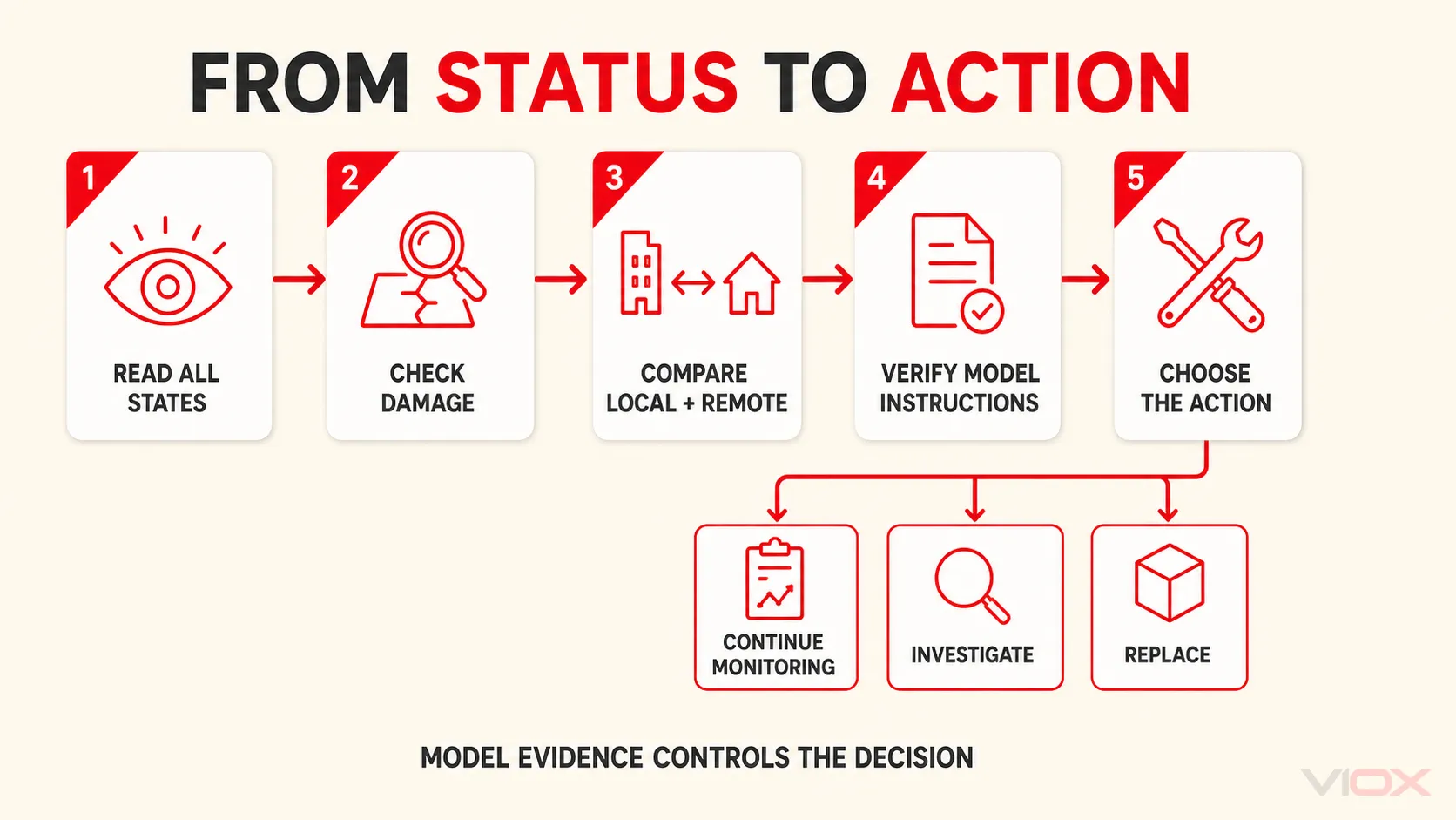
Choose continue monitoring only when the documented state is normal and no damage, significant-event instruction, or application concern requires action. Choose verify or investigate when status is ambiguous, local and remote signals conflict, or failure repeats. Choose replace the indicated module only when the manufacturer permits it and the base is acceptable. Choose replace or escalate the complete assembly when damage, multi-component uncertainty, incompatibility, or unresolved system stress exists.
For model-level evaluation, review the VIOX SPD product family and request the exact status definition, remote-contact diagram, approved replacement mapping, backup-protection instructions, and certification evidence for the intended system and market.
Technical Sources Reviewed
- IEC 61643-01:2024 — Low-voltage surge protective devices, Part 01: General requirements and test methods
- IEC 61643-11:2025 — SPDs connected to AC low-voltage power systems: requirements and test methods
- Phoenix Contact — Example Type 2 SPD with replaceable plugs, local green/red status indication, and remote signaling
- Phoenix Contact — Type 2 surge-protection product range with thermal monitoring and optical status indicators
This article explains status interpretation and diagnostic boundaries. Follow the instructions for the exact SPD and the electrical-safety rules applicable to the installation. Work inside distribution equipment should be performed only by qualified personnel under an approved safe-work procedure.