On this page
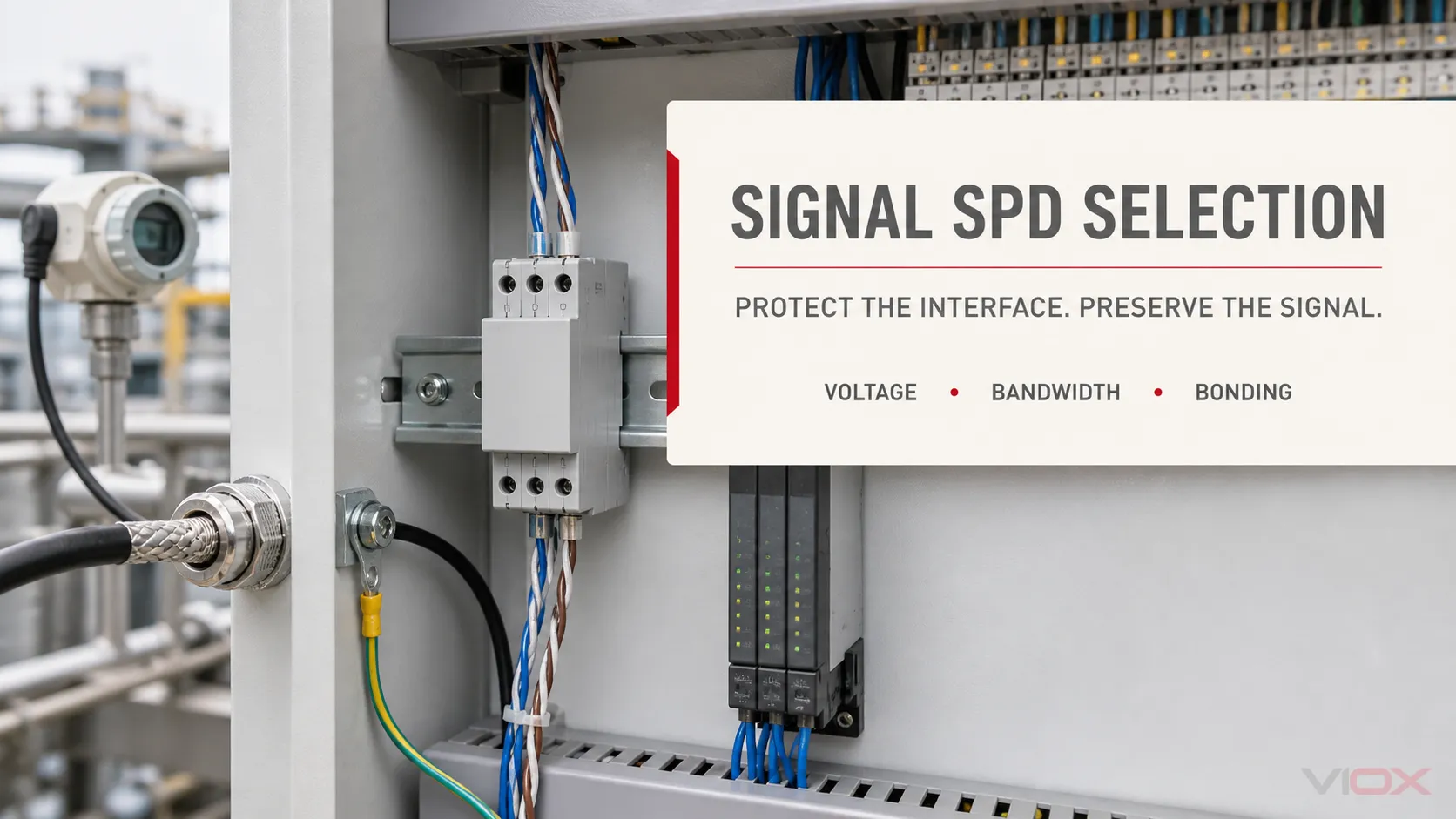
A signal surge protector must do two jobs at once: limit transient voltage and remain effectively transparent to the normal signal. A device can have an impressive surge-current rating yet still be wrong if its operating voltage, series resistance, capacitance, bandwidth, connector or grounding arrangement disrupts RS-485 communication, consumes a 4–20 mA loop’s voltage margin or prevents Ethernet/PoE operation.
Select a signal-line SPD from the interface outward—not from a generic “24 V” or “data protector” label.
Quick Selection Matrix
| Interface | First facts to collect | Normal-operation checks | Installation checks |
|---|---|---|---|
| RS-485 / RS-422 / Modbus RTU | Two- or four-wire, reference conductor, maximum common-mode and differential voltage, baud rate, cable length | Uc, pair balance, capacitance, bandwidth/data rate, series resistance | Terminal assignment, shield strategy, local bonding and each exposed-zone boundary |
| 4–20 mA / HART | Two-, three- or four-wire loop, supply voltage, maximum current, transmitter/load voltage budget | Uc, resistance per conductor, voltage drop, leakage, accuracy and HART compatibility | Field/cabinet locations, shield and equipotential bonding |
| Ethernet / PoE | Category, 100M/1G/2.5G/10G requirement, connector, PoE mode/class and pairs used | Certified data performance, insertion/return loss, PoE voltage/current/power compatibility | Shielded/unshielded design, chassis bond, patching and building entry |
| Coax / CCTV / RF | Connector, characteristic impedance, frequency band, DC feed and maximum RF/pulse power | Insertion loss, return loss/VSWR, bandwidth, Uc and DC-pass requirement | Direct chassis/bulkhead bond and cable-entry location |
| Digital/analog control I/O | DI/DO/AI/AO type, working voltage/current, common reference, frequency or pulse rate | Uc, leakage, resistance, capacitance and channel balance | Wire count, common/reference path and control-cabinet bond |
The protocol name is only a starting point. Different implementations of the same protocol can use different voltages, speeds, cable types and power arrangements.
Why a Power SPD Cannot Replace a Signal SPD
An AC panel SPD is designed for power-system voltage and surge duty. A signal SPD is inserted in or connected to a low-voltage interface and must preserve its transmission characteristics. Using a power SPD on a communication line can leave the equipment insufficiently protected and can heavily load or short the signal.
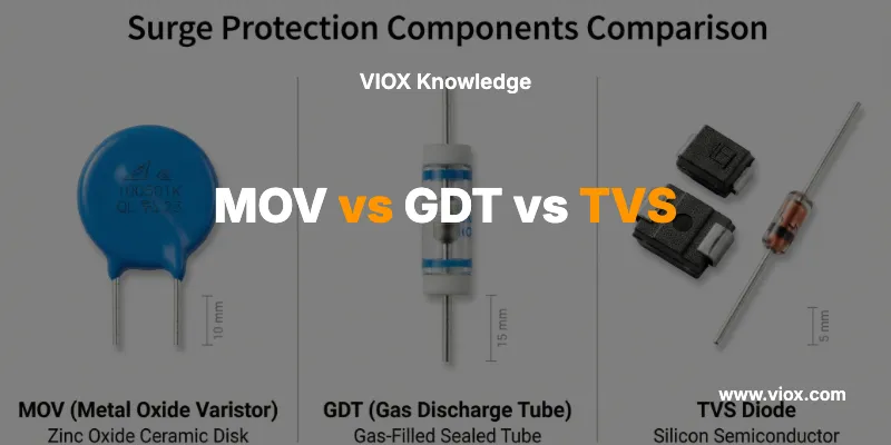
Signal SPDs may use coordinated switching and voltage-limiting stages such as gas-discharge tubes and semiconductor suppressors. Component technology helps explain behavior, but the finished device’s declared interface, voltage-limitation, surge and transmission data—not the component name—should drive selection.
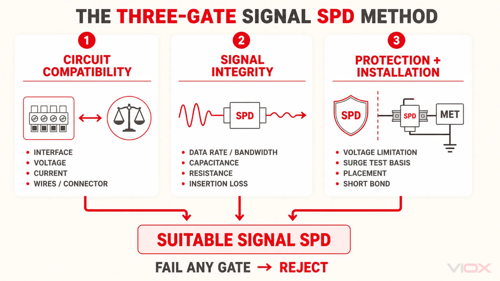
The Three-Gate Selection Method
Every candidate must pass three gates:
- Circuit compatibility: interface, voltage, current, wires/pairs and connector.
- Signal integrity: bandwidth/data rate, capacitance, resistance, leakage, insertion loss and balance.
- Protection and installation: voltage limitation, surge test duty, modes, placement and bonding path.
A device that fails any gate is not a suitable selection.
Gate 1: Define the Exact Interface
Record the standard and the real implementation:
- Signal type or protocol
- Number of conductors and pairs
- Balanced, unbalanced, floating or referenced circuit
- Shielded or unshielded cable
- Connector or terminal style
- Whether power shares the same conductors
- Signal direction and any required galvanic isolation
For RS-485, “Modbus” alone does not define the electrical installation. Confirm two-wire or four-wire operation, reference conductor, baud rate, topology and termination. For Ethernet, record the category and actual link speed. For PoE, also record the applicable power delivery requirements.
Selection output: protected conductors, pair assignment, reference/shield arrangement and connector.
Gate 2: Match Normal and Maximum Circuit Voltage
The SPD’s maximum continuous operating voltage must be above the highest legitimate voltage that can appear across the connected mode during normal service. At the same time, a needlessly high operating voltage can result in less useful voltage limitation for sensitive electronics.
Record separately where relevant:
- Line-to-line or conductor-to-conductor voltage
- Line-to-ground/common voltage
- DC supply voltage and tolerance
- Signal peaks, ringing and common-mode range
- PoE or remote-power voltage on the same cable
Do not select a 24 V signal SPD solely because a control cabinet uses a 24 VDC supply. The actual input circuit, common reference and maximum normal excursion determine the requirement.
Selection output: Uc/maximum working voltage for every protected mode.
Gate 3: Check Current, Resistance and Voltage Budget
A series-connected signal SPD carries normal loop or interface current. Its current rating must cover the real operating condition, including shared power where applicable.
Series resistance creates voltage drop:
Vdrop = I × Rtotal
In a 4–20 mA loop, calculate the SPD drop at maximum loop current and subtract it from the available voltage budget together with cable and load drops. The resulting margin must still satisfy the transmitter and receiving equipment. Also check leakage current where high-impedance or high-accuracy analog inputs are involved.
Selection output: nominal/maximum current, resistance per path, maximum voltage drop and permitted leakage.
Gate 4: Preserve Bandwidth and Data Quality
Protection components and PCB layout add capacitance and insertion effects. Excessive capacitance can slow digital edges; excessive insertion loss or poor impedance control can degrade high-frequency links.
Check the parameter appropriate to the interface:
- Maximum supported data rate and protocol approval
- Analog or RF bandwidth
- Capacitance line-to-line and line-to-ground
- Insertion loss and return loss/VSWR
- Characteristic impedance for coaxial circuits
- Pair balance and crosstalk performance
- HART compatibility for instrument loops
- Ethernet category and negotiated link speed
Do not convert baud rate into a universal minimum bandwidth formula without the signaling method and manufacturer data. Prefer an SPD explicitly characterized for the intended interface.
Selection output: required data rate/frequency range and acceptable transmission limits.
Gate 5: Compare Voltage Limitation on the Same Test Basis
The protected equipment’s port withstand and the SPD’s declared voltage-limitation or protection-level data must be coordinated. “Clamping voltage” is useful shorthand, but catalog values are comparable only when the mode, test waveform, current and measurement method are stated.
Check:
- Line-line and line-ground protection modes
- Declared voltage protection level or output voltage limitation
- Nominal and total discharge-current test data
- Impulse test waveform and category
- Coordination with an upstream coarse-protection stage
- Distance and conductor inductance between SPD and equipment
The lowest catalog voltage is not automatically best if the SPD conducts during normal signaling or cannot carry the interface current.
Selection output: maximum acceptable voltage limitation by mode plus the matched test condition.
Gate 6: Place and Bond the SPD Correctly
A signal SPD needs a low-impedance discharge path to the local equipotential bonding system. A long, indirect earth conductor can add voltage during a fast transient, even when the device itself has suitable laboratory data.
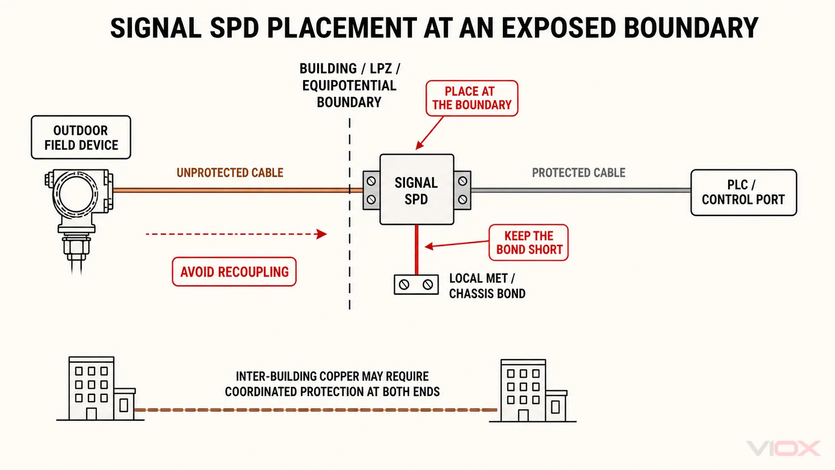
Assess each point where a copper cable crosses a building, lightning protection zone or equipotential boundary. Place the SPD close to that boundary or the protected port, keep the bond short and direct, and avoid routing protected and unprotected cable together in a way that allows recoupling.
Inter-building copper frequently requires coordinated protection at both connected equipment zones because a ground-potential rise can stress either end. This is not a universal “two protectors always” rule: assess the cable route, zone boundaries, local bonding and equipment arrangement. Fiber conversion may be preferable where galvanic isolation is the design objective.
Cable-shield termination and SPD bonding are related but are not the same decision. Follow the EMC, hazardous-area and equipment manufacturer’s grounding design instead of improvising a shield-earth connection.
Selection output: protection locations, bond point and maximum practical bonding-path arrangement.
Interface-Specific Selection Notes
RS-485 and Modbus RTU
Verify two- or four-wire topology, A/B polarity convention, reference conductor, maximum common-mode voltage and baud rate. The SPD should provide balanced protection with sufficiently low capacitance and series resistance. Preserve the bus termination and biasing design; the SPD is not a replacement for either.
For long outdoor or inter-building links, document both differential and common-mode protection and assess each building-entry boundary.
4–20 mA and HART
Record loop supply, transmitter minimum voltage, receiver/load resistance, cable resistance and maximum current. Calculate the remaining voltage margin after adding the SPD. For HART, require explicit HART or suitable frequency-response compatibility rather than assuming every 4–20 mA protector will pass the superimposed digital signal.
Intrinsic-safety and hazardous-area circuits require an approved protection concept and model-specific certification; this general guide cannot establish Ex suitability.
Ethernet and PoE
Match the SPD to the connector, cable category and required link speed. Confirm all data pairs used by the link are protected and that PoE voltage, current, power and pair arrangements are supported by the exact model. Review insertion loss, return loss and shielding/bonding provisions.
IEC 61643-21:2025 explicitly includes telecommunications and signalling networks that can also provide power on the same line, such as PoE. That scope does not mean every IEC 61643-21 device supports every Ethernet or PoE implementation.
Coaxial, CCTV and RF
Match connector family, characteristic impedance and frequency range. Verify insertion loss and return loss across the full operating band, plus any DC pass or remote-power requirement. A bulkhead-mounted protector with a direct chassis bond often gives a more controlled high-frequency discharge path than a long flying earth lead, subject to the equipment design.
Worked Specification 1: Outdoor RS-485 Sensor Link
Suppose an outdoor sensor uses a two-wire RS-485 pair plus a reference conductor and enters a PLC cabinet. The design record should state:
- Maximum differential and common-mode operating voltages
- Baud rate and cable length
- Two protected data conductors plus treatment of the reference conductor
- Acceptable capacitance, resistance and pair imbalance
- Line-line and line-ground voltage-limitation requirements under stated tests
- Cabinet and field-zone protection locations
- Shield and equipotential-bonding arrangement
- Terminal style and environmental requirement
“RS-485 SPD, 5 kA” is not an equivalent specification because it omits the normal interface and test basis.
Worked Specification 2: 4–20 mA/HART Transmitter
For a loop-powered HART transmitter, record the supply tolerance, maximum loop current, transmitter minimum voltage, receiver resistance and cable resistance. Then specify:
- Uc above the maximum legitimate loop voltage in the connected modes
- Current capacity above the maximum loop condition
- Maximum series resistance and calculated voltage drop
- Leakage compatible with accuracy requirements
- HART-compatible transmission behavior
- Coordinated protection at the field and cabinet boundaries where the risk design requires it
- Suitable hazardous-area certification if applicable
This process protects both availability and measurement integrity.
Copy-Ready Signal SPD Enquiry Form
Application and protected equipment:
Interface / protocol:
Wires, pairs and connector:
Shielded or unshielded:
Normal and maximum line-line voltage:
Normal and maximum line-ground/common voltage:
Maximum current / shared power requirement:
Data rate or frequency band:
Maximum acceptable series resistance / voltage drop:
Capacitance, insertion-loss or impedance requirement:
Required protection modes:
Port withstand / maximum voltage-limitation objective:
Required surge test and standard basis:
Cable route and zone/building boundaries:
Local bonding and shield arrangement:
Environment, mounting and certification:
Final Selection Checklist
Reject a candidate if any answer is missing:
- Does it match the exact interface, wire count and connector?
- Is Uc correct for both differential and common-mode normal conditions?
- Can it carry signal and shared power without excessive voltage drop or leakage?
- Is data-rate, bandwidth, capacitance and insertion performance declared?
- Are voltage limitation and surge ratings stated with modes and test conditions?
- Does the installation provide a short bond at the correct boundary?
- Are certification and environmental requirements met?
For model-level verification, send the completed form and interface drawing to the VIOX SPD product team.
References
- IEC 61643-21:2025 — SPDs connected to telecommunications and signalling networks
- IEC 61643-01:2024 — common low-voltage SPD requirements
- Phoenix Contact — industrial signal and data surge-protection selection guide
- Bourns — signal and data line SPD product selector
- DEHN — SPD selection by interface and signal