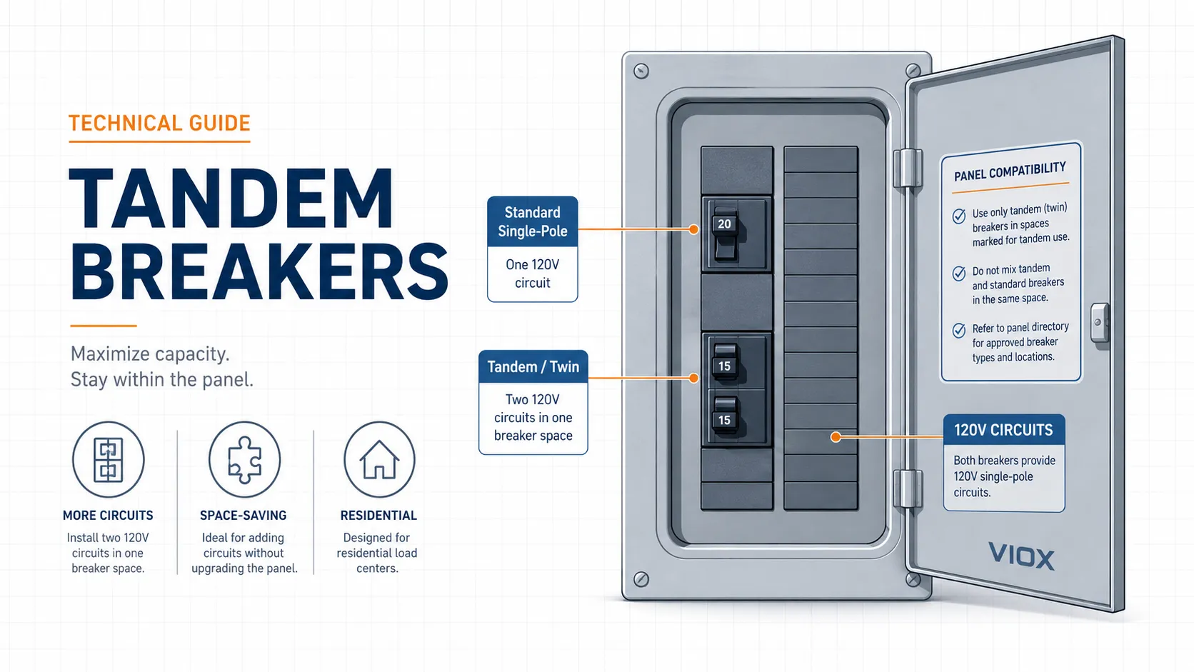
A tandem breaker, also called a twin breaker, duplex breaker, split breaker, or piggyback breaker, fits two independent 120V branch circuits into one full-size breaker space. It is used when a compatible electrical panel has limited physical spaces but still allows additional circuits.
A tandem breaker is safe only when the panel is listed for tandem breakers, the breaker model matches the panel manufacturer’s approved list, and it is installed in a slot designed for tandem use. A tandem breaker is not the same as a double-pole breaker and should not be used as a shortcut around panel capacity, shared-neutral rules, or required AFCI/GFCI protection.
Key Takeaways
Tandem breakers create two separate 120V circuits in one breaker space.
They are also called twin breakers, duplex breakers, split breakers, or piggyback breakers.
They are safe only in panels and slots approved for tandem breakers.
CTL tandem breakers include rejection features to prevent use in non-approved panel spaces.
Non-CTL breakers are generally replacement-type products for older compatible panels, not a way to bypass modern panel limits.
If the panel label says 20 spaces / 20 circuits, tandem breakers are usually not allowed; if it says 20 spaces / 40 circuits, designated tandem slots may be allowed.
Tandem Breaker vs Twin Breaker vs Piggyback Breaker
These terms usually refer to the same general idea: two single-pole breaker handles or circuits in one full-size breaker body.
Term
Common Meaning
Notes
Tandem breaker
Two 120V circuits in one breaker space
Most common technical term
Twin breaker
Same idea as tandem breaker
Common in consumer searches
Duplex breaker
Same general category
Often used by manufacturers or distributors
Piggyback breaker
Informal name for tandem breaker
Sometimes used negatively when installed incorrectly
Split breaker
Informal or regional term
Can be confused with split-bus panels
The name matters less than compatibility. The breaker should match the panel label, bus design, and approved breaker type.
Tandem vs Single-Pole vs Double-Pole Breaker
A common mistake is confusing a tandem breaker with a double-pole breaker. They are physically and electrically different.
Breaker Type
Panel Spaces Used
Output
Typical Use
Single-pole breaker
1
One 120V circuit
Lighting, receptacles, small loads
Tandem / twin / piggyback breaker
1
Two separate 120V circuits
Adding circuits in approved tandem slots
Double-pole breaker
2
One 240V circuit or multi-wire circuit with common trip
Dryer, range, HVAC, water heater, EV charger
Quad breaker
2
Multiple 120V/240V combinations depending on model
Panel-specific space-saving applications
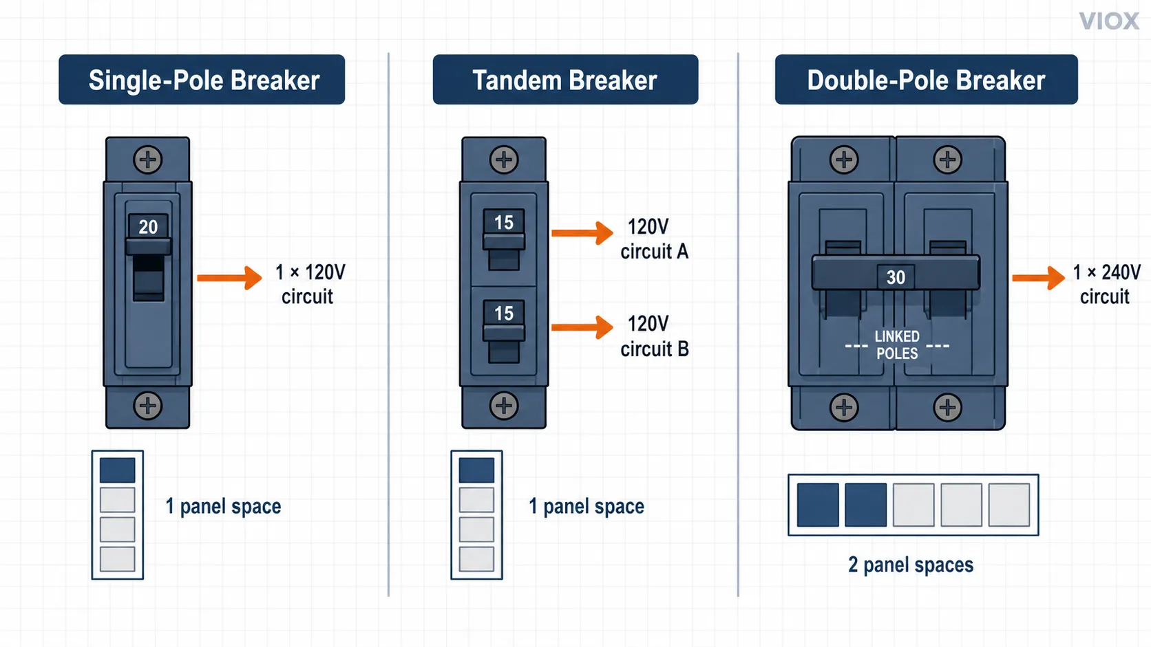
Tandem breaker vs single-pole vs double-pole breaker comparison, showing panel spaces used, output voltage, and circuit count.
A tandem breaker does not provide the same function as a two-pole breaker. It does not automatically give a common trip, and it should not be used for a 240V load unless the exact breaker and panel design are listed for that application.
Are Tandem Breakers Safe?
Tandem breakers are safe when used exactly as the panel manufacturer allows. They become unsafe when used to force extra circuits into a panel that was not designed for them.
Safe Condition
Risk Condition
Panel label allows tandem breakers
Panel label does not allow tandem breakers
Tandem installed in approved slots
Tandem installed in a non-tandem slot
Breaker model is listed for the panel
Breaker brand or series does not match panel approval
Circuit load is calculated correctly
Panel is overcrowded to avoid a needed upgrade
AFCI/GFCI requirements are still met
Tandem used to avoid required protection
Shared-neutral circuits are handled correctly
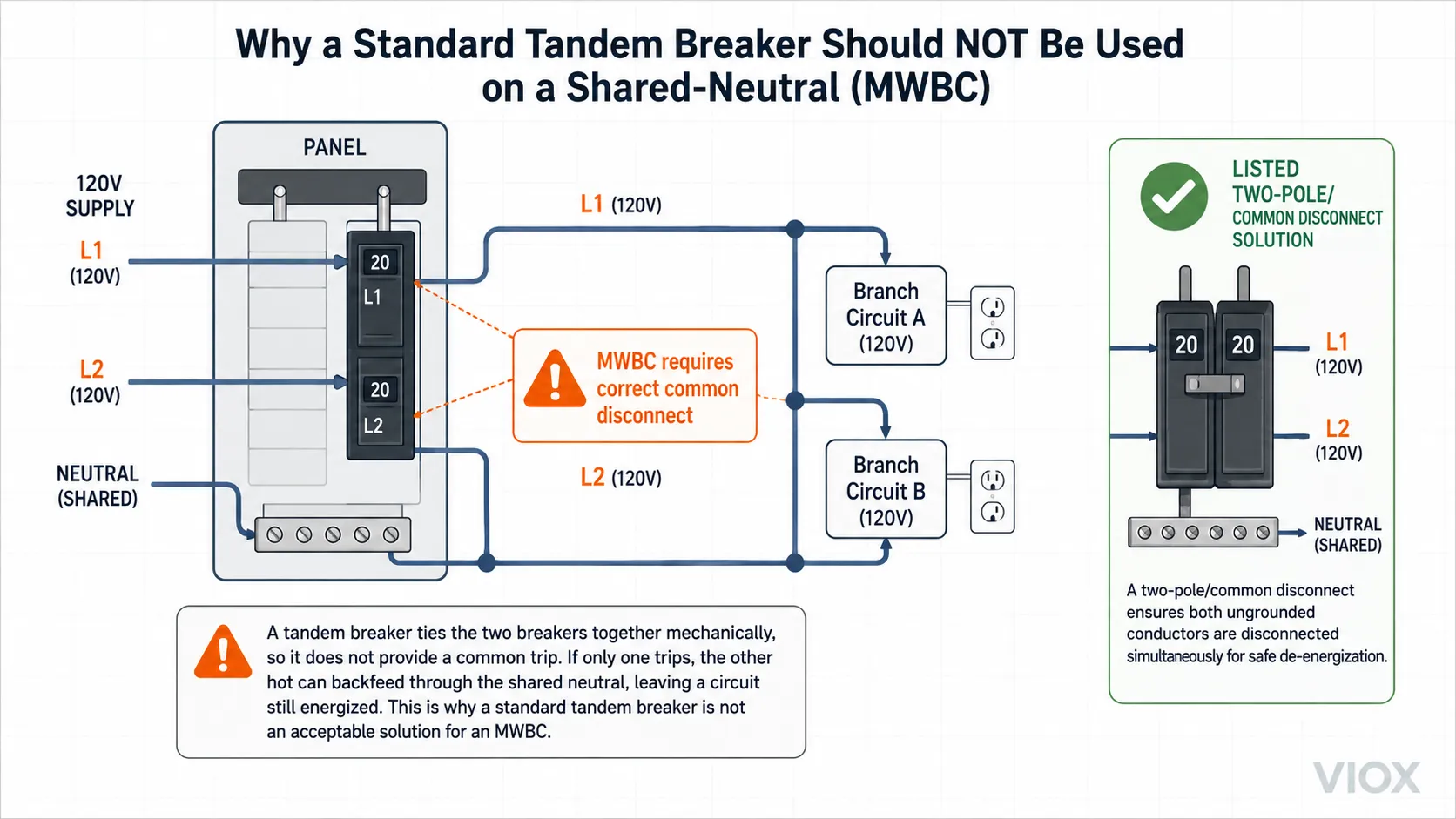
Tandem used on MWBC without correct common disconnect
The safety question is not “are tandem breakers always good or always bad?” The real question is: does this specific panel accept this specific tandem breaker in this specific position?
CTL vs Non-CTL Tandem Breakers
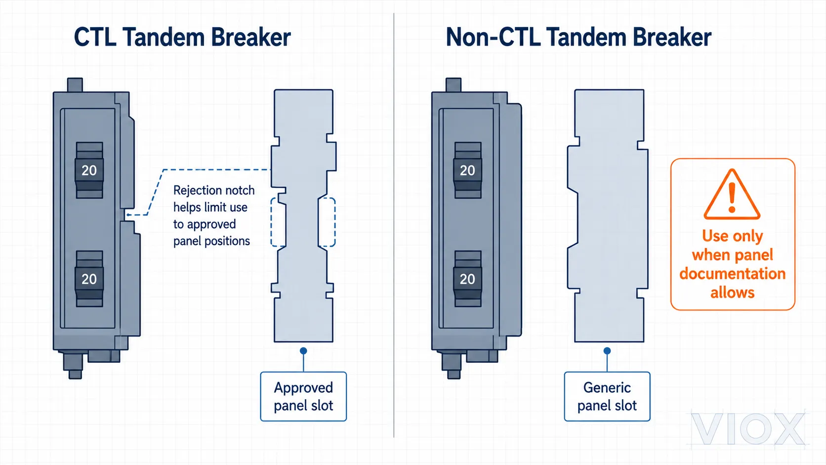
CTL means Circuit Total Limiting. CTL tandem breakers include a rejection feature designed to prevent installation in panel positions that are not intended for tandem breakers.
Item
CTL Tandem Breaker
Non-CTL Tandem Breaker
Meaning
Circuit Total Limiting design
No CTL rejection feature
Typical use
Modern tandem-compatible panels
Replacement use in older compatible panels
Physical feature
Rejection notch or limiting feature
May fit where modern CTL breaker should not
Main purpose
Helps prevent exceeding panel circuit design
Used for legacy panel replacement situations
Main risk
Wrong breaker type or wrong slot
Misused as a “cheater breaker” in modern panels
Selection rule
Check panel label and approved breaker list
Use only when documentation specifically permits
CTL vs non-CTL tandem breaker, showing the rejection feature that prevents installation in non-approved panel positions.
Non-CTL breakers should not be treated as a universal workaround. If a modern panel rejects a CTL tandem breaker, that is usually a sign that the slot or panel is not intended for tandem use.
How to Know If Your Panel Accepts Tandem Breakers
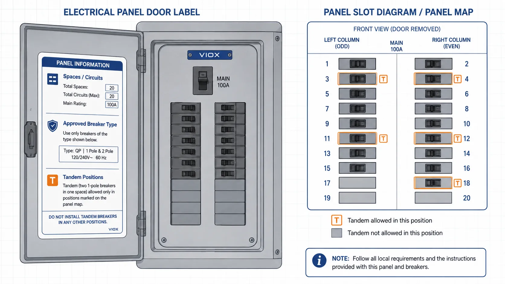
The panel label is the first place to check. It may be inside the panel door or on the enclosure. It usually lists the number of spaces, number of circuits, approved breaker types, and sometimes which positions accept tandem breakers.
Electrical panel label showing spaces/circuits rating and tandem breaker approved positions for safe installation.
Look for:
spaces/circuits rating, such as 20/20, 20/40, 30/40, or 40/80
diagram showing where tandem breakers are allowed
approved breaker type or catalog number
CTL or tandem breaker notes
restrictions for AFCI, GFCI, or two-pole breakers
maximum bus rating and main breaker rating
If the panel label is missing or unreadable, the safe approach is to identify the exact panel model and check manufacturer documentation. Guessing based on physical fit is not enough.
How Many Tandem Breakers Are Allowed in a 100 Amp Panel?
The number of tandem breakers allowed in a 100 amp panel is not determined only by the 100A service rating. It depends on the panel’s spaces/circuits rating, bus design, label diagram, and approved breaker list.
Examples:
Panel Marking
What It Usually Means
20 spaces / 20 circuits
Tandem breakers are usually not allowed
20 spaces / 30 circuits
Some tandem positions may be allowed
20 spaces / 40 circuits
Tandems may be allowed in designated positions
30 spaces / 40 circuits
Limited tandem use may be allowed
The service size also matters. Even if a panel physically accepts tandem breakers, the total load must still be calculated. Tandem breakers add circuit positions; they do not increase the panel’s service capacity.
Why Tandem Breakers Should Not Be Used on Shared-Neutral MWBC Circuits
A multi-wire branch circuit (MWBC) uses two hot conductors sharing one neutral. These circuits require correct handle tie or common disconnect rules so that the shared neutral is not left energized unexpectedly.
Tandem breaker shared-neutral MWBC warning, showing why common disconnect matters for safety on multi-wire branch circuits.
A standard tandem breaker can create problems because the two 120V circuits may end up on the same phase or without the required common disconnect. This can overload the neutral or create a maintenance hazard.
For shared-neutral circuits, the correct solution usually involves a listed two-pole breaker or a breaker assembly specifically designed for that application. Do not assume a tandem breaker is acceptable because it has two handles.
Do Tandem AFCI or GFCI Breakers Exist?
AFCI and GFCI protection with tandem breakers is more complicated than standard tandem protection. Availability depends on the panel brand, breaker series, jurisdiction, and whether the circuit requires AFCI, GFCI, or dual-function protection.
If a circuit requires AFCI or GFCI protection:
verify the exact breaker model listed for the panel
confirm whether a tandem AFCI, tandem GFCI, or tandem dual-function breaker is available for that panel series
check whether the local electrical code and inspector accept that configuration
use a full-size breaker, subpanel, or panel upgrade if no listed option exists
The important point is not whether a tandem AFCI/GFCI breaker exists somewhere in the market. The important point is whether the exact required breaker exists for your exact panel and application.
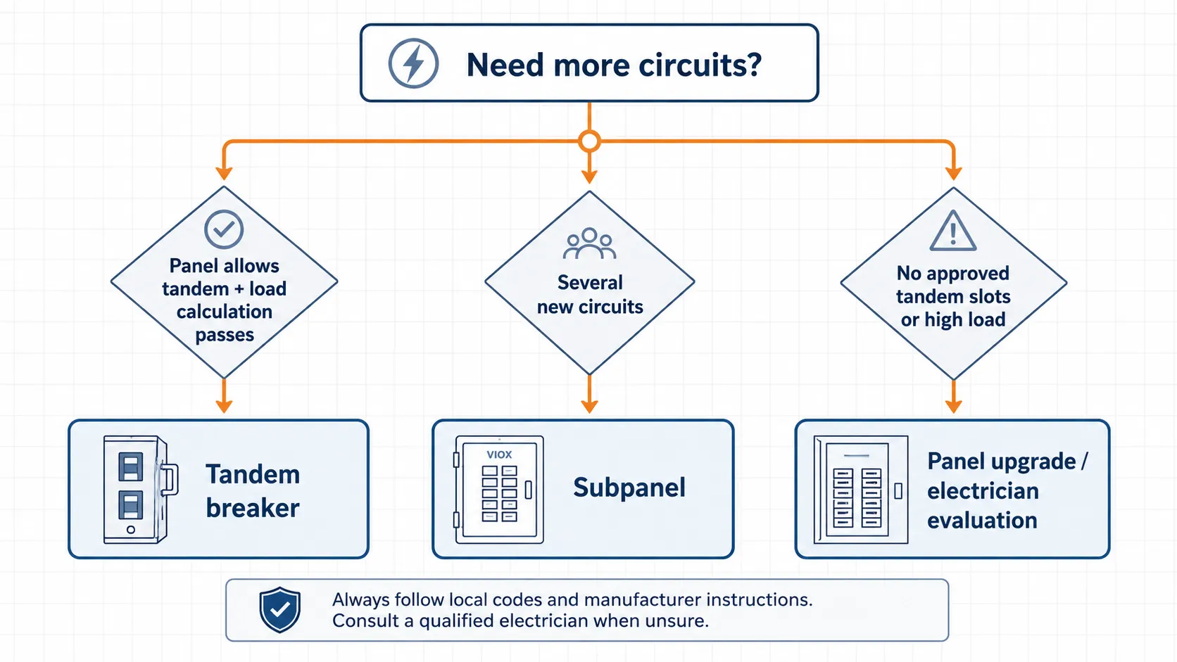
When to Use a Tandem Breaker vs Subpanel vs Panel Upgrade
Situation
Better Option
Reason
Panel allows tandems and load calculation passes
Tandem breaker
Efficient use of approved panel spaces
Panel has no tandem-approved slots
Subpanel or panel upgrade
Avoids using non-approved breaker positions
Several new circuits are needed
Subpanel
Cleaner expansion and better future capacity
High-load circuit is being added
Load calculation and possibly panel upgrade
Tandem breaker does not increase service capacity
AFCI/GFCI requirement cannot be met with tandem
Full-size protected breaker or subpanel
Protection requirement comes first
Panel is old, damaged, or poorly labeled
Evaluation by qualified electrician
Compatibility cannot be confirmed safely
Decision guide for choosing a tandem breaker, subpanel, or panel upgrade based on space, load, and protection requirements.
Tandem breakers solve a space problem, not a capacity problem. If the real issue is load, heat, aging equipment, or missing protection, a tandem breaker is not the right fix.
Common Tandem Breaker Mistakes
Mistake 1: Using a Tandem Breaker Because It Physically Fits
Physical fit is not approval. Breakers should match the panel listing and be used only in approved positions.
Mistake 2: Using Non-CTL Breakers as Cheater Breakers
Non-CTL breakers may fit in places where they should not be used. This can exceed the panel’s designed circuit count.
Mistake 3: Confusing Tandem Breakers with Double-Pole Breakers
A tandem breaker gives two 120V circuits in one space. A double-pole breaker uses two spaces and is designed for 240V or common-trip applications.
Mistake 4: Ignoring AFCI or GFCI Requirements
If a circuit requires AFCI or GFCI protection, adding a basic tandem breaker may not meet the requirement.
Mistake 5: Adding Circuits Without a Load Calculation
Tandem breakers do not increase the service rating of the panel. Too many circuits can still create overload and overheating risks if the load is not evaluated.
A tandem breaker is a breaker that provides two separate 120V circuits in one full-size breaker space. It is also called a twin, duplex, split, or piggyback breaker.
Are tandem breakers safe?
They are safe when used in a panel that is listed for tandem breakers and installed in an approved position with the correct breaker type. They are unsafe when used to exceed panel limits or bypass required protection.
What is the difference between CTL and non-CTL breakers?
CTL breakers include a rejection feature to prevent installation in non-approved tandem positions. Non-CTL breakers lack that feature and are generally intended for replacement use in older compatible panels.
How many tandem breakers are allowed in a 100 amp panel?
It depends on the panel label, not just the 100A rating. Check the spaces/circuits marking and the manufacturer’s breaker diagram. A 20/20 panel usually does not allow tandems, while a 20/40 panel may allow tandems in designated slots.
Is a tandem breaker the same as a double-pole breaker?
No. A tandem breaker provides two separate 120V circuits in one space. A double-pole breaker uses two spaces and is designed for 240V loads or circuits requiring common trip.
Can I use a tandem breaker for a 240V appliance?
Usually no. Most 240V appliances require a listed double-pole breaker. Do not use a tandem breaker unless the breaker and panel are specifically listed for that configuration.
Do tandem GFCI or AFCI breakers exist?
Availability depends on the panel brand, breaker series, and required protection type. If the circuit requires AFCI or GFCI protection, verify the exact listed breaker model for that panel.
Can I add tandem breakers instead of upgrading my panel?
Sometimes, if the panel is designed for tandem breakers and the load calculation allows it. If the panel is full because the electrical load has grown, a subpanel or panel upgrade may be the safer long-term solution.
Conclusion
Tandem breakers are useful when a compatible panel needs more branch circuits without adding more physical breaker spaces. They are not inherently unsafe, but they are often misused.
The correct question is not “can I make it fit?” The correct question is whether the panel label, breaker listing, slot position, circuit type, AFCI/GFCI requirements, and load calculation all allow it. If any of those checks fail, a subpanel or panel upgrade is usually a better answer than forcing in another piggyback breaker.
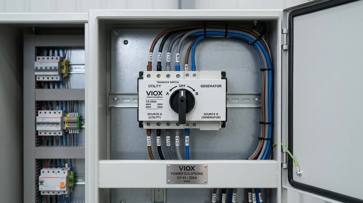
A professionally installed changeover switch within a low-voltage distribution panel, clearly routing dual power sources.
A changeover switch is an electrical switching device that transfers a load from one power source to another while keeping both sources safely isolated from each other. In generator backup systems, dual-feed distribution boards, and essential-load panels, it is the component that governs how and when source transfer occurs — and, critically, prevents the two sources from ever meeting on the load side.
This guide covers everything you need to know: how a changeover switch works, the differences between manual and automatic types, how to choose the right one for your project, and the installation and maintenance practices that keep the system safe over time.
The sections below cover working principle, type selection between manual and automatic variants, pole configuration, standards compliance (IEC 60947-6-1, UL 1008), and the practical selection and installation decisions that determine whether a changeover switch performs reliably over a 20-year service life.
Changeover Switch at a Glance
Item
Details
Core function
Transfer an electrical load from one source to another
A changeover switch — also called a transfer switch in North American practice — connects a load to one of two available power sources at any given time. Its internal mechanism ensures that when one source is connected, the other is physically disconnected. That mutual exclusion is what separates a changeover switch from an ordinary switch or contactor arrangement: the device is purpose-built to prevent two live sources from meeting on the load side.
Consider a 400 V three-phase commercial building supplied by the utility grid and backed up by a 250 kVA standby diesel generator. The changeover switch sits between both sources and the distribution board. During normal operation, current flows from the grid through the switch to the load. When the grid drops below the undervoltage threshold — typically set around 85 % of nominal — the switch transfers the load to the generator. When the grid recovers and holds steady above pickup voltage for the programmed delay period, the load transfers back. At no point during this sequence are both sources connected simultaneously.
That isolation matters more than many specifiers realize. Paralleling two unsynchronized sources — even for a few cycles — can produce fault currents well above the prospective short-circuit level at the installation point, trip upstream protective devices, and push generator power back onto the utility network. A properly rated changeover switch eliminates that risk by design, which is exactly why IEC 60947-6-1 and UL 1008 treat the interlock mechanism as a primary safety function rather than an optional feature.
How Does a Changeover Switch Work?
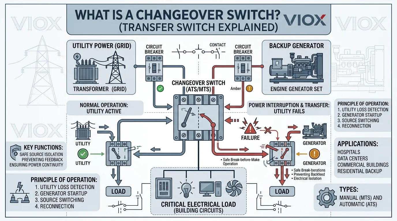
Infographic detailing the operational workflow and power transfer mechanism between the utility grid and a backup generator.
The working principle of a changeover switch is built around a mutually exclusive contact arrangement. Three sets of terminals — source A (main supply), source B (backup), and load — connect through internal contacts that move between two stable positions. The mechanical or electrical design enforces a rule that only one source feeds the load at any instant.
Normal Operation
Under normal conditions the changeover switch rests in its preferred position. The load draws power from the primary source — usually the utility grid. The backup source terminals sit open, and the generator may be off entirely or running on standby at idle.
Detection of a Transfer Condition
A transfer condition arises when the preferred source falls outside acceptable parameters. In a manual changeover switch, the operator notices lights out (or gets a call) and walks to the panel. In an automatic changeover switch, the controller monitors source voltage and frequency continuously. Most controllers trip on sustained undervoltage — a setting between 80% and 90% of nominal is common — or complete loss of phase. IEC 60947-6-1 defines specific test sequences for verifying that the sensing function responds correctly under both gradual voltage decay and instantaneous loss conditions.
The Transfer Sequence
During transfer, the switch breaks the connection to the failed source before making the connection to the backup. This break-before-make action is the fundamental operating requirement. In most designs there is an intentional dead time between disconnecting one source and connecting the other — typically 50–100 ms for automatic units using motorized mechanisms, and effectively instantaneous (within one mechanical stroke) for rotary manual switches, though the total outage for manual transfer includes generator startup time.
IEC 60947-6-1 classifies automatic transfer switching equipment (ATSE) by transfer time: Class A for equipment that does not limit the interruption duration, Class B for medium-interruption (≤ 150 ms), and Class C for short-interruption (≤ 20 ms with stored-energy mechanisms). UL 1008, which governs the North American market, specifies comparable transfer and withstand tests but uses a different classification framework centered on total system transfer time including engine-generator start.
Once the backup source is connected and stable, the load resumes operation on the alternative supply.
Return Transfer (Retransfer)
When the original source recovers, the switch performs the same sequence in reverse. Automatic changeover switches typically include a programmable retransfer delay — 5 to 30 minutes is standard practice — to confirm the returning source is stable and avoid transferring back into a utility reclose cycle or unstable recovery. Manual units rely on the operator to confirm source health and initiate the return.
Interlock Mechanisms
In manual changeover switches, a mechanical interlock physically prevents the switch handle from engaging both positions — usually a sliding bar or cam arrangement that locks one contact set open when the other is closed. In automatic units, electrical interlocking through the controller logic is the primary barrier, often supplemented by a mechanical interlock on the contactor or switch mechanism. Some designs include a third center-off position where neither source connects, which IEC 60947-6-1 recognizes as an additional isolation state useful for maintenance procedures.
Types of Changeover Switches
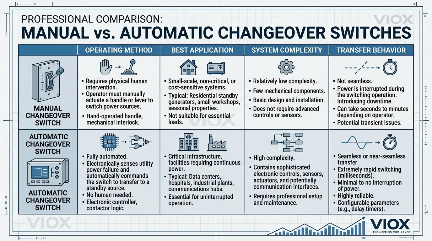
The most consequential distinction in the changeover switch market is between manual and automatic operation. Getting this decision wrong means either spending on automation the project does not need, or leaving a critical load unprotected when nobody is around to flip a handle.
Manual Changeover Switch
A manual changeover switch requires an operator to physically move the switching mechanism from one position to the other. There is no controller, no voltage-sensing circuit, and no automatic start signal to the generator. The operator detects the outage, starts the backup source, confirms stable output, and turns the handle.
Typical products range from 63 A rotary switches for single-phase residential panels to 3200 A enclosed manual transfer switches for industrial distribution boards. Construction standards vary by market — IEC 60947-3 covers manual switches in international markets, while UL 1008 covers them in North America when the device is specifically listed as transfer switch equipment.
Where manual changeover switches earn their place:
Residential generator backup where someone is normally home.
Small commercial installations — a 30 kVA genset backing up a retail shop — where staff can respond within a few minutes.
Basic standby systems where the load tolerates an interruption measured in minutes rather than seconds.
Projects where the owner wants direct, visible control over the source-transfer decision.
Advantages. Fewer parts. Lower purchase price — a quality 100 A 4-pole manual changeover switch typically costs 30–50% less than an equivalent automatic unit. No control-circuit power dependency. Extremely long mechanical life, often exceeding 10,000 operations.
Limitations. Dead in the water without a person present. An outage at 2 AM on a public holiday means the load stays dark until someone arrives. For refrigeration, life-safety, server rooms, or process loads with narrow interruption tolerance, that gap is unacceptable.
Automatic Changeover Switch
An automatic changeover switch monitors both power sources continuously and executes the transfer without human intervention. When the controller detects that the preferred source has dropped below threshold, it sends a start signal to the generator, waits for the engine to reach stable voltage and frequency (typically 10–15 seconds for a properly maintained diesel set), and then transfers the load. When the preferred source returns and holds within tolerance for the retransfer delay, the switch moves the load back and shuts down the generator.
In project specifications, product catalogs, and most international standards documentation, the automatic changeover switch is designated as automatic transfer switching equipment (ATSE) under IEC 60947-6-1, or as an automatic transfer switch (ATS) under UL 1008. The terms overlap almost completely in practice.
Where automatic changeover switches are the baseline requirement:
Hospitals and healthcare facilities — most building codes mandate automatic transfer for life-safety and critical branch loads.
Data centers operating at Tier II or above.
Commercial buildings where outage cost exceeds several hundred dollars per minute.
Industrial operations running continuous processes — a kiln, an extrusion line, a batch reactor.
Telecom sites and infrastructure installations that may sit unattended for weeks.
Any site where the insurance policy, the SLA, or the building code says transfer must happen without a phone call.
Advantages. Fast, unattended transfer — total outage typically under 15 seconds from utility loss to generator on load, depending on engine start time and ATSE class. Removes operator error from the transfer sequence. Integrates with generator auto-start systems, BMS, and SCADA platforms. Provides event logging for compliance and maintenance records.
Limitations. Higher unit cost, more complex control wiring, and a commissioning process that requires coordinated testing with the generator and upstream protection. The controller, voltage-sensing circuits, and motorized mechanism all require periodic functional testing — quarterly at minimum for critical installations, per most facility maintenance standards.
Critical loads, unattended sites, facilities requiring fast recovery
Mechanical life
Very long (simple mechanism, fewer wear parts)
Long, but controller and motor components add maintenance scope
Integration with BMS/SCADA
Not applicable
Standard feature on most modern units
Governing standards
IEC 60947-3, UL 1008 (manual class)
IEC 60947-6-1 (ATSE), UL 1008 (automatic class)
Decision Framework
Choose a manual changeover switch when the load can ride through an interruption lasting several minutes, a trained person will always be available on site, the project budget favors simplicity, or the installation is a residential or small commercial backup with a sub-100 kVA generator.
Choose an automatic changeover switch when the load is essential or life-safety classified, the facility may be unoccupied during an outage, the specification or code requires transfer within a defined time window (often ≤ 10 seconds), or the system must feed status data to centralized monitoring.
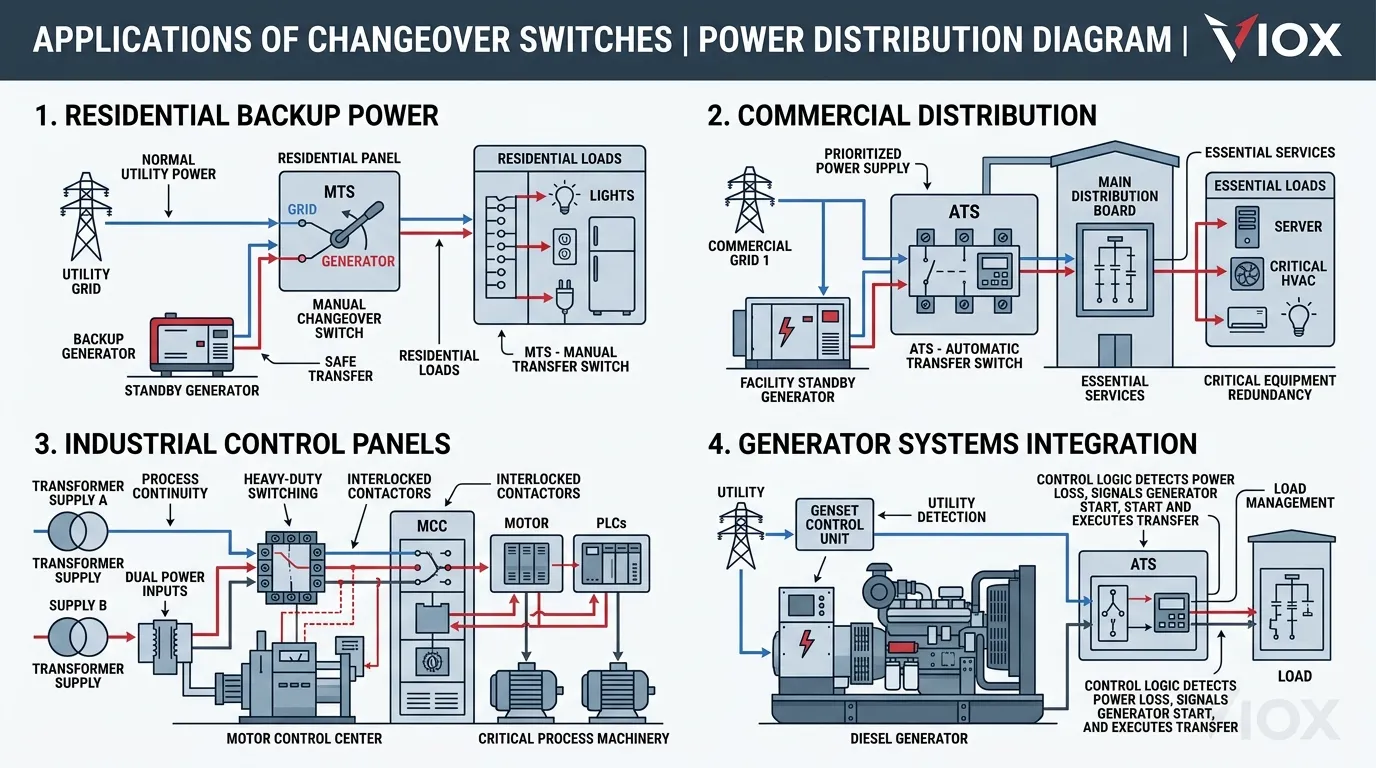
Changeover Switch Applications
Schematic overview of standard changeover switch applications across residential, commercial, and industrial electrical distribution systems.
Residential Backup Power
The generator changeover switch is one of the most common residential electrical upgrades in outage-prone areas. A typical installation connects the utility supply and a portable or permanently installed generator to a changeover switch mounted adjacent to the main distribution board. Selected circuits — or the entire house, depending on generator capacity — feed through the switch so the homeowner can transfer to generator power when the grid drops.
Manual changeover switches dominate this segment. A 63 A or 100 A 4-pole manual unit handles most single-phase residential loads at a fraction of the cost of an automatic system. Homes with medical equipment, home offices running revenue-generating operations, or whole-house standby generators increasingly spec automatic units — particularly where the homeowner travels frequently and the house may be unoccupied during a storm.
Commercial Buildings
Offices, retail spaces, hotels, and mixed-use buildings use changeover switches to maintain power to essential systems: emergency lighting, fire alarm panels, elevators, IT closets, point-of-sale infrastructure, and HVAC controls. In most jurisdictions — IEC, NEC, and regional building codes alike — life-safety loads on the emergency branch require automatic transfer. Non-essential loads may sit behind a separate manual unit on a lower-priority panel.
A mid-rise commercial building might have a 400 A automatic changeover switch on the essential-load board feeding emergency lighting and fire systems, plus a 630 A manual unit on the standby board serving HVAC and general power. That split keeps the automatic equipment where it is legally required and controls cost on the rest.
Industrial Facilities
Manufacturing plants, processing facilities, and warehouses frequently operate with dual-feed utility arrangements or dedicated standby generators rated from 500 kVA to several MVA. Industrial changeover switches in these environments handle higher current ratings — 800 A, 1600 A, 3200 A — and must coordinate with upstream protective devices, downstream motor loads, and sometimes capacitor banks that create re-energization transients.
The choice between PC class and CB class construction becomes critical at these ratings. PC class (power contactor) devices built to IEC 60947-6-1 are purpose-designed for transfer duty and typically offer higher mechanical endurance. CB class devices use circuit breakers as the switching elements, adding built-in overcurrent protection but with different contact wear characteristics.
Telecom and Data Infrastructure
Cell towers, switching centers, and data halls demand the highest power continuity levels. Automatic changeover switches in these installations often feature redundant controllers, bypass isolation for maintenance without load interruption, and Modbus/SNMP communication interfaces for NOC-level remote monitoring. Transfer time requirements at Tier III and Tier IV data centers may be specified in cycles (≤ 4 cycles at 50 Hz = 80 ms), pushing the design toward stored-energy or static transfer mechanisms rather than conventional motorized ATSE.
Hybrid and Multi-Source Systems
Solar-plus-storage installations, microgrids, and facilities with both generator and inverter backup may need changeover switches managing more than two sources — or managing two sources with tighter transition constraints than a standard open-transition device can provide. In these arrangements the changeover function becomes part of a broader power-management architecture that may include open and closed transition transfer modes, where closed transition briefly parallels the two sources under synchronized conditions before breaking the original connection.
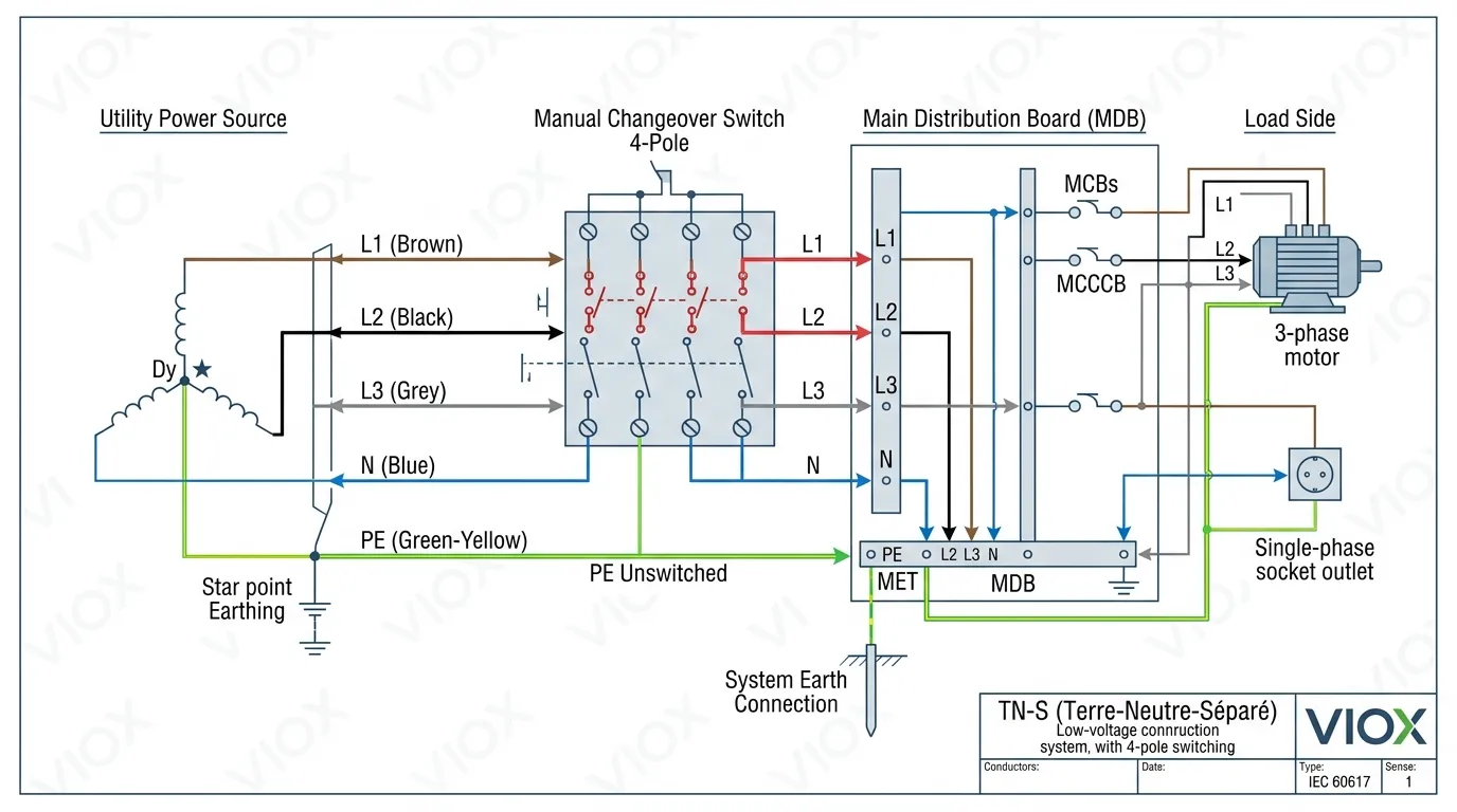
Pole Configuration: Matching the Changeover Switch to the System
Wiring schematic of a TN-S low-voltage distribution system utilizing 4-pole switching to ensure complete isolation of the neutral conductor.
Changeover switches are manufactured in 2-pole, 3-pole, and 4-pole configurations. The correct pole count depends on the electrical system and the earthing arrangement — not simply the number of phases.
Configuration
Typical Application
2-pole
Single-phase systems where neutral is not switched
3-pole
Three-phase systems where neutral is common and not switched
4-pole
Three-phase systems where neutral must be switched (standard in TN-S, IT, and certain TT earthing arrangements)
Choosing the wrong pole configuration is one of the most persistent specification errors in source-transfer design. A three-phase system does not automatically call for a 3-pole changeover switch. If the earthing arrangement, the generator neutral bonding scheme, or local code requires switched neutral — and in most TN-S systems with separately derived generator sources, it does — a 4-pole unit is mandatory. Failing to switch the neutral in these systems creates a parallel neutral path between sources, which can cause circulating currents, nuisance RCD tripping, and unreliable ground-fault detection.
Selecting the right changeover switch for a project means working through a series of technical and operational decisions in the correct sequence. Skip a step, and the product either will not fit the installation or will not perform as expected under real fault conditions.
Step 1: Define the Source Arrangement
Identify exactly which two sources the switch must manage. Utility plus generator is the dominant pair, but the sources could be two independent utility feeders (common in dual-bus industrial substations), a utility feed and an inverter, or a generator and a UPS bypass output. The source characteristics — nominal voltage, frequency, phase count, available fault current — set the electrical boundaries for the switch.
Step 2: Decide Between Manual and Automatic Operation
Almost always the first major commercial decision. Review the load’s maximum tolerable interruption time, the availability of trained operators, the building code requirements for the load classification, and the project budget. On many projects, this single decision cuts the product shortlist in half.
Step 3: Match Electrical Ratings
Confirm that the changeover switch is rated for the system voltage (e.g., 230/400 V, 277/480 V), the maximum continuous current at the point of installation, the prospective short-circuit current (Isc) with appropriate withstand rating (Icw for ATSE per IEC 60947-6-1, or short-circuit current rating per UL 1008), and the correct number of poles. Undersizing creates a safety hazard. Oversizing wastes budget and panel space — a 1600 A switch where 630 A would suffice is not conservative engineering, it is poor specification.
Step 4: Evaluate Load Characteristics
Motor-heavy loads, capacitor banks, and non-linear loads (VFDs, large UPS, LED driver arrays) impose transient inrush and harmonic demands that the changeover switch must withstand. Verify the product’s making capacity (peak closing current) and breaking capacity against the actual load profile, not just the steady-state thermal rating. IEC 60947-6-1 specifies dedicated test sequences for motor loads, and the switch datasheet should confirm rated values under these conditions.
Step 5: Consider Transition Type
Most changeover switches use open transition — break-before-make — which is the simplest and most common approach. Some applications benefit from closed transition (make-before-break), where the two sources are briefly paralleled under synchronized conditions (typically for 100 ms or less) before the original source disconnects. Closed transition requires frequency-matched sources, synchronism-check relaying, and additional protective logic. It is standard practice on large data center and healthcare campus projects where even sub-second interruptions disrupt sensitive load processes. Refer to our open vs. closed transition guide for detailed selection criteria.
Step 6: Verify Standards and Certification
For international markets, confirm the changeover switch carries IEC 60947-6-1 type-test certification from an accredited laboratory (e.g., KEMA, CESI, TÜV). For North American installations, require UL 1008 listing or CSA C22.2 No. 178 certification. The product should also comply with the relevant assembly standard — IEC 61439-1/-2 if installed in a type-tested switchboard, or UL 891 for North American switchboard applications. Do not accept manufacturer self-declarations without supporting type-test reports ; the standards exist precisely to validate performance claims under fault and endurance conditions.
Step 7: Review Installation and Environmental Conditions
Check available panel space, the enclosure IP rating required for the environment (indoor clean, outdoor, dusty, humid, washdown), cable entry positions, and service access clearances mandated by local code (IEC 61439 or NEC 110.26). A switch that satisfies every electrical parameter but cannot physically be installed, accessed, or maintained is not the right switch.
Step 8: Align With the Project’s Transfer Philosophy
Some facility owners prioritize simplicity and visible operator control — a straightforward handle they can see in the down position. Others prioritize speed, automation, and remote visibility with full BMS integration. The changeover switch should match the operating philosophy of the building and the maintenance team that will own the system for the next two decades.
Installation Essentials for Changeover Switches
Professional Installation Is Non-Negotiable
A changeover switch sits at the boundary between two live power sources. Incorrect wiring, a missing interlock, or improper grounding can create backfeed onto the utility network, arc flash hazards for maintenance personnel, and equipment damage from unsynchronized paralleling. Installation must be performed by a licensed electrician experienced with source-transfer equipment and familiar with the applicable local code — whether that is the IEC/BS wiring regulations, the NEC, the Australian AS/NZS 3000, or another national standard.
Key Installation Steps
The general sequence: de-energize both sources and apply lockout/tagout, mount the switch in the designated enclosure or panel position per manufacturer clearance requirements, terminate the utility (source A) supply cables, terminate the generator or backup (source B) supply cables, terminate the load output cables, install control wiring for automatic units (generator start/stop, voltage sensing, communication bus), establish earthing and bonding per the system earthing arrangement (TN-S, TN-C-S, TT, IT), and commission with a full transfer test in both directions — including verifying interlock operation by deliberately attempting to close both sources simultaneously.
Critical Safety Points
Backfeed prevention. The changeover switch must make it mechanically and electrically impossible for generator power to feed back onto the utility network. This is a code requirement in every major jurisdiction and a primary concern for utility companies and lineworkers. UL 1008 and IEC 60947-6-1 both include interlock verification as a mandatory type-test element.
Neutral handling. In 4-pole configurations, verify that the neutral contacts operate in the correct overlap sequence relative to the phase contacts. IEC 60947-6-1 Annex H provides guidance on neutral switching sequences. Incorrect neutral timing can create transient overvoltages or, worse, a floating neutral condition that exposes single-phase loads to line-to-line voltage.
Grounding. The equipment grounding conductor must be continuous and unbroken through the switch assembly. Do not rely on the enclosure chassis or mounting hardware as the sole ground path — use a dedicated bonding jumper or terminal.
Labeling. Mark the switch with source identification (SOURCE A: UTILITY, SOURCE B: GENERATOR), operating instructions for manual units, emergency contact information, and any interlock or lockout requirements. In an emergency, the person operating the switch may not be the person who normally manages the electrical system.
Maintenance and Troubleshooting
Preventive Maintenance Schedule
Interval
Manual Changeover Switch
Automatic Changeover Switch
Monthly
Visual check for corrosion, loose hardware, signs of overheating
Visual check plus controller status LED/display review
Quarterly
Exercise the switch through a full transfer cycle under reduced load
Full functional test: simulate outage, verify auto-start signal, transfer, retransfer, and generator cooldown/shutdown
Annually
Torque-check all connections per manufacturer spec, lubricate mechanism, inspect contacts for pitting or discoloration
All quarterly tasks plus controller calibration, contact resistance measurement (milliohm meter), thermographic scan of connections, and full-load transfer test
Common Issues and Solutions
Switch handle stiff or difficult to operate (manual units). Corrosion ingress, dried lubricant, or mechanical binding from misalignment after years of thermal cycling. Strip down per the manufacturer’s service manual, clean contact pivot points, re-lubricate with the specified grease (not WD-40), and check for physical obstructions or enclosure distortion.
Automatic switch fails to transfer during a real outage. Check controller power supply — many ATSE controllers draw power from the source they are monitoring, and if that source has failed the controller may be dead. Verify voltage-sensing connections at both source terminals. Confirm the generator start signal reaches the engine controller. Review pickup/dropout voltage settings — if someone tightened the dropout threshold to 90% to solve a nuisance-transfer complaint, the controller may not recognize a brownout at 88% as a transfer condition. The most frequent root cause in field investigations is a broken sensing wire or a blown control fuse that went undetected between test cycles.
Nuisance transfers on automatic units. The switch transfers to generator during brief voltage dips that do not actually warrant a transfer — a compressor starting on a neighboring circuit, a utility reclose event, or a capacitor switching transient. Widen the dropout time delay (2–5 seconds is common for non-critical loads) or narrow the voltage dropout threshold. Confirm that the sensing input has appropriate filtering and is not picking up electrical noise from VFDs or switching power supplies sharing the same panel.
Arcing or discoloration on contacts. Indicates undersized contacts for the actual load (common when motor inrush was not accounted for), excessive make/break operations under load, or contacts at end of electrical life. Measure contact resistance with a DLRO (digital low-resistance ohmmeter) — if resistance exceeds the manufacturer’s published limit (typically 50–200 µΩ depending on rating), replace the contact assembly. On large-frame units, contact replacement is a field-serviceable operation; on smaller units, it may require factory reconditioning.
Changeover Switch vs. Transfer Switch
In everyday usage, changeover switch and transfer switch describe the same device: a switch that moves a load between two power sources with mechanical or electrical interlock preventing simultaneous connection.
The terminology splits along geographic and standards lines. Changeover switch is prevalent in IEC-standard markets — Europe, the Middle East, Africa, Asia-Pacific, and most of Latin America. Transfer switch dominates in North American practice, anchored by UL 1008 terminology and NEC Article 700/701/702 language. The IEC standards themselves use the designation automatic transfer switching equipment (ATSE) rather than either colloquial term.
What matters for specification is not the label on the nameplate but the device’s rated voltage, continuous current rating, short-circuit withstand, pole configuration, transition type (open or closed), transfer time class, and certification to the applicable standard. A UL 1008-listed transfer switch and an IEC 60947-6-1-certified changeover switch performing the same function are, for engineering purposes, equivalent devices validated through different but comparable test regimes.
Common Selection Mistakes to Avoid
Treating all changeover switches as interchangeable. A manual 63 A 2-pole switch for a single-phase home and an automatic 63 A 4-pole ATSE with integrated controller serve entirely different applications. Same current number, different universe.
Selecting on current rating alone. The changeover switch must also match system voltage, phase configuration, pole count, short-circuit withstand (Icw or SCCR), and transition type. Current rating is necessary but nowhere near sufficient.
Ignoring neutral-switching requirements. In TN-S systems with a separately derived generator source, failing to switch the neutral creates a parallel path that causes circulating currents, nuisance RCD/GFCI tripping, and unreliable earth-fault detection. This is the single most common engineering error in source-transfer design, and it surfaces after commissioning when it is expensive to fix.
Specifying manual operation for an unattended site. If nobody will be on site to operate the switch — a cell tower, a pump station, a warehouse on a Sunday — the transfer will not happen. Match the operating method to actual staffing patterns, not to budget aspirations.
Overlooking maintenance access. A changeover switch installed behind a cable tray, above a false ceiling, or in a panel with 150 mm clearance to the adjacent wall will be neglected. IEC 61439 and NEC 110.26 prescribe minimum working clearances for a reason — respect them during layout, not as an afterthought during commissioning.
Accepting products without accredited type-test certification. A changeover switch that has not been type-tested to IEC 60947-6-1 or listed to UL 1008 by an independent laboratory is an unknown quantity under fault conditions. For equipment sitting between two power sources and protecting against backfeed, “unknown” is not an acceptable risk class.
Conclusion
A changeover switch is the device responsible for moving a load safely between two power sources. It sits at the heart of every generator backup system, every dual-feed distribution arrangement, and every essential-load panel where source continuity matters. Getting the selection right means understanding the source pair, choosing between manual and automatic operation, matching electrical ratings and pole configuration to the system, verifying compliance with IEC 60947-6-1 or UL 1008, and aligning the product with how the facility actually operates day-to-day.
Manual changeover switches earn their place where simplicity, low cost, and direct operator control are the priorities. Automatic changeover switches are the clear choice where the load is critical, the site may be unattended, or the code and the client both demand fast, hands-free transfer.
The right starting point for any selection decision is a single practical question: How should this load move between its two sources, and how quickly does that transfer need to happen?
FAQ
What is a changeover switch?
A changeover switch is an electrical device that transfers a load between two power sources — typically a utility supply and a generator — while preventing both sources from being connected to the load at the same time. It provides safe, controlled source transfer during outages, maintenance, or planned switching events. The device is governed by IEC 60947-6-1 (international) and UL 1008 (North America).
How does a changeover switch work?
A changeover switch uses a mutually exclusive contact arrangement to connect the load to one source at a time. When the connected source fails or a transfer is initiated, the switch disconnects the current source and then connects the alternative. A mechanical or electrical interlock — validated as a primary safety function under both IEC 60947-6-1 and UL 1008 — prevents both sources from being connected simultaneously.
What are the main types of changeover switches?
The two main types are manual changeover switches, which require an operator to move the switch handle, and automatic changeover switches (designated as ATSE under IEC 60947-6-1), which use a controller to detect source failure and execute the transfer without human intervention.
What is the difference between a changeover switch and a transfer switch?
Functionally identical. “Changeover switch” is the predominant term in IEC-standard markets worldwide, while “transfer switch” is the standard designation in North American (UL/NEC) practice. The IEC standards use the formal designation “automatic transfer switching equipment (ATSE).”
Where are changeover switches used?
Residential generator backup systems, commercial buildings, industrial facilities, hospitals, data centers, telecom sites, and any installation where a load must be transferred between two power sources safely and reliably.
Can a changeover switch be used in a three-phase system?
Yes. Changeover switches are available in 2-pole, 3-pole, and 4-pole configurations for single-phase and three-phase systems. The correct pole count depends on the phase arrangement and whether the neutral must be switched — which is determined by the system earthing arrangement (TN-S, TN-C-S, TT, IT) and local code requirements.
When should I choose an automatic changeover switch over a manual one?
When the load is critical or life-safety classified, the facility may be unoccupied during an outage, the specification requires transfer within a defined time window (often ≤ 10 seconds per IEC 60947-6-1 Class B), or the system must integrate with BMS/SCADA platforms.
How long does a changeover switch last?
A quality unit with proper maintenance typically operates reliably for 15 to 25 years. Manual units tend to have longer mechanical life due to fewer electronic components. Automatic units may require controller board or motor mechanism replacement during their service life, depending on the number of accumulated operations versus the manufacturer’s rated mechanical and electrical endurance.
What size changeover switch do I need?
The switch must be rated for the system voltage and the maximum continuous load current at the installation point. It must also carry a short-circuit withstand rating (Icw per IEC 60947-6-1 or SCCR per UL 1008) appropriate for the available fault current. Have a licensed electrician perform a load analysis and verify fault levels before sizing.
Can I use a changeover switch with solar panels or battery storage?
Yes. In hybrid and multi-source systems, changeover switches manage transfer between utility power, inverter output, battery storage, or generator backup. These installations may require additional control logic and, in some cases, closed-transition transfer capability to avoid disrupting sensitive loads during source handoff.
Is it safe to install a changeover switch myself?
No. A changeover switch sits between two live power sources and involves work on main distribution circuits. Incorrect installation can create lethal backfeed, arc flash hazards, and code violations. Use a licensed electrician with experience in source-transfer equipment.
How often should I test my changeover switch?
Manual units: exercise through a full transfer cycle at least quarterly, with an annual connection torque check, contact inspection, and lubrication. Automatic units: full functional test monthly — including simulated outage, generator start, transfer, retransfer, and shutdown sequence — with comprehensive annual servicing including contact resistance measurement, thermographic scanning, and controller calibration.
What standards apply to changeover switches?
The primary international standard is IEC 60947-6-1, which covers automatic transfer switching equipment (ATSE) including test requirements for electrical endurance, short-circuit withstand, and transfer time classification. In North America, UL 1008 covers transfer switch equipment. Manual changeover switches used outside of a dedicated transfer-switch listing may also fall under IEC 60947-3 (switch-disconnectors). Assemblies containing changeover switches should comply with IEC 61439 (international) or UL 891 (North America).
Power outages can strike without warning, potentially damaging expensive equipment and disrupting critical operations. No Fuse Circuit Breakers (NFB) represent a crucial advancement in electrical protection technology, offering superior safety and reliability compared to traditional fused systems. Whether you’re an electrical engineer designing industrial systems or a facility manager ensuring operational continuity, understanding NFBs is essential for modern electrical installations.
A No Fuse Circuit Breaker is an electrical protection device that automatically interrupts current flow during overload or short circuit conditions without using replaceable fuse elements. Unlike traditional systems that rely on melting wires or strips, NFBs use sophisticated electromagnetic and thermal-magnetic mechanisms to detect faults and protect electrical circuits. This guide covers everything you need to know about NFB technology, selection, and applications.
Understanding No Fuse Circuit Breakers (NFB)
Basic Definition and Function
A No Fuse Circuit Breaker (NFB) is fundamentally a protective switching device designed to safeguard electrical circuits from damage caused by overcurrent conditions. The term “no fuse” specifically distinguishes these breakers from older designs that incorporated backup fuses for high fault current protection.
The primary function of an NFB involves three critical operations:
Normal operation: Conducting electrical current with minimal resistance
Fault detection: Sensing abnormal current conditions through magnetic or thermal sensors
Circuit interruption: Physically separating contacts to stop current flow and extinguish resulting electrical arcs
NFB vs Traditional Fused Breakers
The evolution from fused to non-fused circuit breakers represents a significant technological advancement. Historically, many molded case circuit breakers included current-limiting fuses to handle extremely high short circuit currents. These “fused breakers” combined the switching capability of circuit breakers with the current-limiting performance of fuses.
Key differences include:
Traditional Fused Breakers:
Required replacement fuses after high-current faults
Limited to single-use protection elements
Combined mechanical switching with fuse protection
Higher maintenance costs due to consumable components
No Fuse Breakers:
Fully resettable protection without replacement parts
Advanced contact design achieves high interrupting capacity
Reduced long-term operational costs
More reliable operation in industrial environments
The development of “fuseless current limiting circuit breakers” in the early 1960s by companies like Klockner-Moeller used innovative horseshoe-shaped current paths where magnetic forces would force contacts open faster during high fault currents.
How Do No Fuse Circuit Breakers Work?
Working Principle
No Fuse Circuit Breakers operate on sophisticated protection principles that eliminate the need for replaceable fuse elements. The fundamental operation involves continuous monitoring of electrical current and automatic interruption when abnormal conditions occur.
During Normal Operation:
Current flows through main contacts with minimal resistance
Monitoring systems continuously measure current levels
Thermal and magnetic sensors remain within normal operating ranges
Overcurrent detection triggers through thermal or magnetic mechanisms
Trip mechanism activation releases stored mechanical energy
Contact separation occurs rapidly to interrupt current flow
Arc extinguishing systems cool and elongate the electrical arc until extinction
Key Components
Contact System: The heart of any NFB lies in its contact system. Modern current limiting breakers employ magnetic forces generated by fault current to ‘blow apart’ contacts faster than normal operation. This rapid contact separation limits the amount of fault current that can flow through the circuit.
Trip Mechanism: NFBs utilize either thermal-magnetic or electronic trip mechanisms:
Thermal protection: Bimetallic strips bend when heated by overcurrent, triggering the mechanism
Magnetic protection: Electromagnetic coils create magnetic fields that activate trip mechanisms during short circuits
Electronic protection: Microprocessor-based systems provide precise control and multiple protection functions
Arc Extinguishing System: When contacts separate under load, an electrical arc forms between them. NFBs employ sophisticated arc chutes with metallic splitter plates that:
Break the arc into multiple smaller arcs
Extract energy through cooling metallic surfaces
Increase arc resistance to facilitate extinction
Prevent re-ignition of the arc
Types of No Fuse Circuit Breakers
MCCBs (Molded Case Circuit Breakers)
Molded Case Circuit Breakers represent the most common type of NFB used in commercial and industrial applications. MCCBs have typical current ratings ranging from 100 to 2500 A and may have rated short-circuit ratings up to 50 kA at 415 V.
Key Characteristics:
Current Range: 10A to 2500A
Voltage Ratings: Up to 1000V AC
Breaking Capacity: 10kA to 200kA
Trip Settings: Fixed or adjustable depending on model
Applications: Motor protection, feeder circuits, main distribution
Construction Features:
Molded plastic housing provides insulation and protection
Thermal-magnetic or electronic trip units
Multiple pole configurations (1, 2, 3, or 4 poles)
Optional auxiliary contacts and accessories
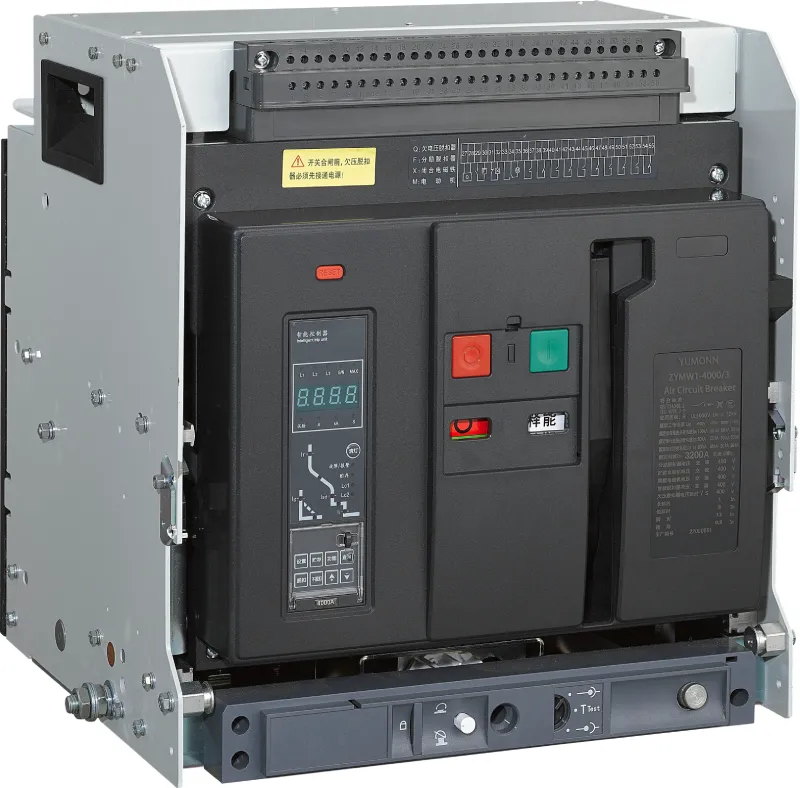
Air Circuit Breakers (ACBs)
Air Circuit Breakers represent the high-end category of NFBs, designed for critical applications requiring maximum performance and flexibility.
Key Specifications:
Current Range: 800A to 6300A
Breaking Capacity: Up to 100kA+
Voltage Ratings: Up to 690V AC
Advanced Features: Electronic trip units, communication capabilities, remote operation
Applications:
Main switchboard protection
Generator circuit protection
Critical industrial processes
Data center power distribution
Current Limiting NFBs
Current limiting circuit breakers are certified by UL to limit the let-through I²t during a fault to not more than the I²t available during a half cycle of the prospective symmetrical short circuit current.
Advanced Protection Features:
Faster fault clearing: Limits fault current magnitude and duration
Reduced equipment stress: Protects downstream equipment from high fault currents
Enhanced safety: Minimizes arc flash hazards
System coordination: Improves selectivity with other protective devices
NFB vs MCB vs MCCB: Key Differences
Comprehensive Comparison Table
Feature
NFB/MCCB
MCB
Fused Breaker
Current Rating
10-2500A
0.5-125A
Varies with fuse
Breaking Capacity
10-200kA
6-18kA
Very High (with fuses)
Adjustability
Available in some models
Fixed
Fixed
Physical Size
Large
Compact
Medium
Cost
Higher initial
Lower
Medium
Maintenance
Low
Minimal
High (fuse replacement)
Reset Time
Immediate
Immediate
Requires fuse replacement
Applications
Industrial/Commercial
Residential/Light Commercial
Specialized high-fault
Coordination
Excellent
Good
Limited
Remote Operation
Available
Limited
Not typically
When to Choose Each Type
Choose NFB/MCCB When:
Current requirements exceed 125A
High fault currents are present (>18kA)
Adjustable trip settings are needed
Motor starting applications require coordination
Remote operation or monitoring is required
Industrial or commercial environments
Choose MCB When:
Residential or light commercial applications
Current requirements under 125A
Cost is a primary consideration
Simple, fixed protection is adequate
Space is limited in distribution panels
Choose Fused Breakers When:
Extremely high fault currents exceed NFB capacity
Current limiting is critical for equipment protection
Specific applications require fuse protection by code
Backup protection for critical circuits
Advantages of No Fuse Circuit Breakers
Operational Benefits
Resettable Protection: The most significant advantage of NFBs over fused systems is their resettable nature. After a fault condition clears, operators can restore power immediately without replacing components. This feature dramatically reduces downtime and maintenance requirements.
Faster Response Times: NFBs typically have response times of 0.02-0.05 seconds compared to 0.002 seconds for fuses. While fuses are faster, NFBs provide adequate protection speed for most applications while offering superior convenience.
Adjustable Trip Settings: Many NFB models offer adjustable trip settings, allowing fine-tuning of protection characteristics to match specific load requirements. This flexibility enables:
Optimal coordination with other protective devices
Customization for specific motor starting characteristics
Adaptation to changing load conditions
Enhanced system selectivity
Visual Trip Indication: NFBs provide clear visual indication of trip status through handle position, making fault diagnosis faster and more reliable than fused systems.
Economic Advantages
Long-term Cost Savings: While NFBs have higher initial costs than fuses, the total cost of ownership is typically lower due to:
No ongoing fuse replacement costs
Reduced labor for maintenance
Minimized downtime during faults
Lower spare parts inventory requirements
Reduced Maintenance: NFBs require significantly less maintenance than fused systems:
No consumable parts to replace
Longer service intervals
Self-contained protection mechanisms
Reduced inspection requirements
Safety Features
Enhanced Protection Capabilities: Modern NFBs offer multiple protection functions in a single device:
Overload protection: Thermal elements protect against sustained overcurrents
Short circuit protection: Magnetic elements provide instantaneous protection
Improved Arc Flash Safety: Current limiting NFBs reduce arc flash energy by limiting fault current magnitude and duration, significantly improving personnel safety during maintenance and operation.
Common Applications of NFB Circuit Breakers
Industrial Applications
Motor Protection: NFBs excel in motor protection applications due to their ability to handle high starting currents while providing precise overload protection. NFBs are commonly used to secure motor load currents and can be set to specific current limits based on motor requirements.
Typical motor protection settings:
Continuous current: 115-125% of motor full load current
Instantaneous trip: 8-15 times FLC for squirrel cage motors
Time delay: Coordination with motor starting characteristics
Heavy Machinery Circuits: Industrial equipment often requires NFBs due to:
High current demands
Frequent starting/stopping cycles
Need for selective coordination
Remote operation requirements
Power Distribution Panels: NFBs serve as main and feeder breakers in industrial distribution systems, providing:
High fault current interruption capability
Coordination with downstream devices
Monitoring and communication features
Maintenance-friendly operation
Commercial Applications
Office Buildings: Modern commercial buildings rely on NFBs for:
HVAC system protection: Large air conditioning and heating equipment
Elevator circuits: High-power motor drives
Emergency systems: Critical life safety equipment
Data center power: Uninterruptible power supplies and server equipment
Voltage Specifications: NFB voltage rating must equal or exceed system voltage:
480V systems: Use 600V rated NFBs
208V systems: Use 240V or 600V rated NFBs
International applications: Consider 400V, 690V ratings
DC applications: Ensure DC voltage compatibility
Breaking Capacity Determination: The interrupt rating of an MCCB ranges from 10k to 200k amperes, while MCBs have interrupt ratings up to 1800 amperes.
Selection Guidelines:
Obtain fault study data from qualified electrical engineer
Use conservative approach when exact data unavailable
Consider system growth that may increase fault levels
Standard ratings: 10kA, 25kA, 35kA, 50kA, 65kA, 100kA
Calculation Examples
Motor Protection Example: For a 75HP, 480V, 3-phase motor:
Intermittent tripping: without obvious load issues
Visible signs of overheating: at connection points
Voltage drops: across connection points
Burning odors: or discoloration
Correction:
Tighten all connections to specified torque values
Replace damaged hardware such as lugs or bolts
Clean connection surfaces to remove oxidation
Apply appropriate compounds to prevent future corrosion
Environmental Factors
Temperature Effects: All breakers are expected to operate at 40 degrees Celsius, with thermal breakers de-rating after this temperature, but hydraulic-magnetic circuit breakers maintaining performance until 85 degrees Celsius.
High Temperature Solutions:
Improve ventilation in electrical enclosures
Use temperature-compensated breakers for extreme environments
De-rate current settings based on ambient temperature
Install cooling systems for critical applications
Humidity and Contamination: Environmental contamination affects NFB performance:
Moisture: Can cause insulation breakdown and corrosion
Dust: Interferes with mechanical operation
Chemical vapors: May corrode components
Salt air: Accelerates corrosion in coastal areas
Environmental Protection:
Specify appropriate enclosure ratings (NEMA, IP)
Use environmental sealing for harsh conditions
Implement regular cleaning schedules
Apply protective coatings where appropriate
Failure to Trip Issues
Testing Procedures: When NFBs fail to trip during fault conditions, immediate action is required:
Safety Precautions:
De-energize circuit before testing
Use proper PPE including arc flash protection
Follow lockout/tagout procedures
Have qualified personnel perform testing
Diagnostic Tests:
Trip mechanism function: Manual operation test
Thermal element: Heat simulation test
Magnetic element: Current injection test
Contact condition: Resistance and gap measurements
When to Replace: Replace NFBs immediately if they exhibit:
Failure to trip during test conditions
Mechanical binding or rough operation
Visible damage to housing or components
Exceeded service life recommendations
Future of No Fuse Circuit Breaker Technology
Smart NFB Features
Digital Monitoring Capabilities: Modern NFBs increasingly incorporate advanced digital technologies:
Real-time Monitoring:
Current measurement: Continuous monitoring of all phases
Voltage tracking: Detection of under/over voltage conditions
Power quality analysis: Harmonic monitoring and power factor measurement
Temperature monitoring: Internal and ambient temperature sensing
Q1: What exactly is a No Fuse Circuit Breaker (NFB)? A: A No Fuse Circuit Breaker (NFB) is an electrical protection device that automatically interrupts electrical current during overload or short circuit conditions without using a fuse element. Unlike traditional fused breakers that rely on a melting wire or strip, NFBs use electromagnetic or thermal-magnetic mechanisms to detect faults and trip the breaker. The term “no fuse” emphasizes that these breakers don’t require replaceable fuse elements for protection.
Q2: Why is it called a “No Fuse” breaker when most circuit breakers don’t use fuses anyway? A: The term originated historically when many circuit breakers actually contained backup fuses for high fault current protection. In the 1960s-80s, some molded case circuit breakers included current-limiting fuses to handle extremely high short circuit currents. The “NFB” designation specifically indicated breakers that achieved high interrupting capacity through advanced contact design and arc extinguishing technology without needing internal fuses.
Q3: Is NFB the same as MCCB? A: Yes, in most cases. NFB (No Fuse Breaker) is primarily a marketing term used to describe MCCBs (Molded Case Circuit Breakers) that don’t contain internal fuses. The vast majority of modern MCCBs are actually NFBs. However, technically, any circuit breaker without fuses could be called an NFB, including MCBs and ACBs.
Technical Differences & Comparisons
Q4: What’s the difference between NFB and MCB? A: The main differences are:
– Current Rating: NFBs/MCCBs handle 10-2500A, while MCBs handle 0.5-125A
– Breaking Capacity: NFBs have higher fault interrupting capacity (up to 200kA) vs MCBs (up to 18kA)
– Adjustability: Some NFBs offer adjustable trip settings; MCBs have fixed settings
– Size: NFBs are larger and designed for industrial/commercial use
– Applications: NFBs protect motors and heavy equipment; MCBs protect residential circuits
Q5: Can I use a circuit breaker instead of a fuse? A: Generally yes, but with important considerations:
– Voltage and current ratings must match or exceed the original fuse specifications
– Breaking capacity must be adequate for the fault current at that location
– Physical compatibility with the existing panel or switchgear
– Code compliance – some applications specifically require fuses for current limiting
– Coordination with other protective devices may need recalculation
Selection & Sizing
Q6: How do I choose the right NFB for my application? A: Follow these key steps:
1. Calculate total load current and select NFB rated 125% of continuous load
2. Determine voltage rating – must equal or exceed system voltage
3. Check breaking capacity – must exceed maximum available fault current
4. Consider environmental factors – temperature, humidity, altitude
5. Verify physical fit in existing panels
6. Check coordination with upstream and downstream protective devices
Q7: What current rating should I choose for motor protection? A: For motor protection with NFB:
– Continuous rating: 115-125% of motor full load current (FLC)
– Instantaneous trip setting: 8-15 times FLC for squirrel cage motors, 3-6 times for wound rotor motors
– Consider starting current – motors can draw 6-8 times normal current during startup
– Check manufacturer recommendations in motor nameplate and documentation
Applications & Usage
Q8: When should I use NFB instead of MCB? A: Use NFB/MCCB when you need:
– Higher current ratings (above 125A)
– Greater fault interrupting capacity (above 18kA)
– Adjustable trip settings for coordination
– Motor starting applications with high inrush currents
– Industrial/commercial environments with higher power demands
– Remote operation capabilities
Q9: Can NFBs be used for residential applications? A: While technically possible, NFBs are rarely used in residential settings because:
– Oversized for typical loads (most homes need 15-60A protection)
– More expensive than necessary for residential applications
– Larger physical size doesn’t fit standard residential panels
– MCBs provide adequate protection for typical household circuits
Installation & Maintenance
Q10: Do I need an electrician to install an NFB? A: Yes, NFB installation should always be performed by qualified electricians because:
– High voltage and current levels present serious safety risks
– Code compliance requirements for proper installation
– Coordination studies may be needed with existing systems
– Proper torque specifications required for connections
– Testing and commissioning needed to verify proper operation
Q11: How often should NFBs be tested or maintained? A: Recommended maintenance schedule:
– Visual inspection: Monthly (check for overheating, physical damage)
– Operational testing: Annually (manual operation of handles)
– Electrical testing: Every 3-5 years (contact resistance, trip timing)
– Professional inspection: Every 5-10 years depending on application criticality
– Immediate attention if frequent tripping, overheating, or physical damage occurs
Troubleshooting & Problems
Q12: Why does my NFB keep tripping? A: Common causes of NFB tripping:
– Overload conditions: Load exceeds breaker rating
– Short circuits: Wiring faults or equipment failures
– Ground faults: Insulation breakdown or moisture
– Loose connections: Creating heat and resistance
– Aging equipment: Worn contacts or calibration drift
– Environmental factors: Extreme temperatures affecting trip points
Q13: What does it mean when an NFB handle is in the middle position? A: The middle position indicates the breaker has tripped due to a fault:
– Not manually turned off (handle would be fully down)
– Protection function activated (overload, short circuit, or ground fault)
– Reset procedure: Move handle to full OFF position, then back to ON
– Investigate cause before resetting to prevent repeated tripping
Conclusion
No Fuse Circuit Breakers represent a critical evolution in electrical protection technology, offering superior performance, reliability, and cost-effectiveness compared to traditional fused systems. Understanding NFB technology, proper selection criteria, and maintenance requirements enables electrical professionals to design and maintain safer, more efficient electrical systems.
Key takeaways include:
NFBs provide resettable protection without consumable fuse elements
Proper selection requires careful analysis of current, voltage, and fault current requirements
Professional installation and maintenance ensure optimal performance and safety
Modern NFBs offer advanced features including digital monitoring and communication capabilities
For critical applications requiring reliable electrical protection, consult with qualified electrical engineers to ensure proper NFB selection, coordination, and installation. The investment in quality NFB protection systems pays dividends through improved safety, reduced downtime, and lower long-term maintenance costs.
Whether protecting industrial motors, commercial HVAC systems, or critical power distribution equipment, No Fuse Circuit Breakers provide the reliable, maintainable protection modern electrical systems demand.
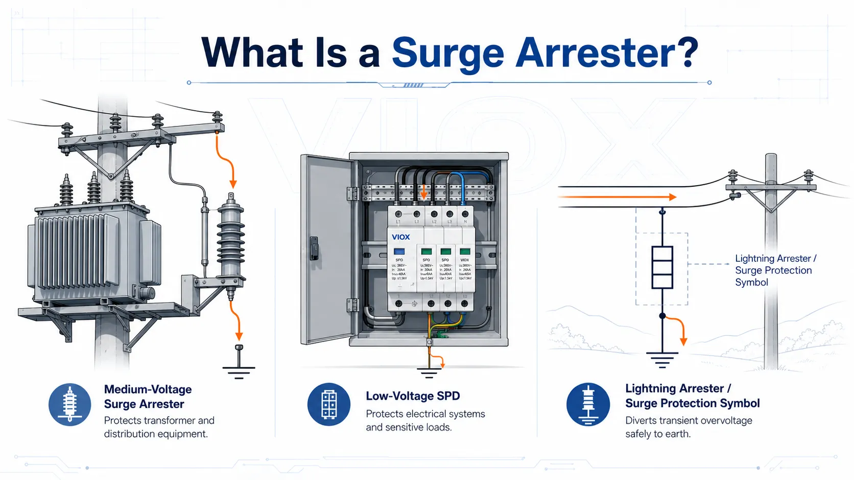
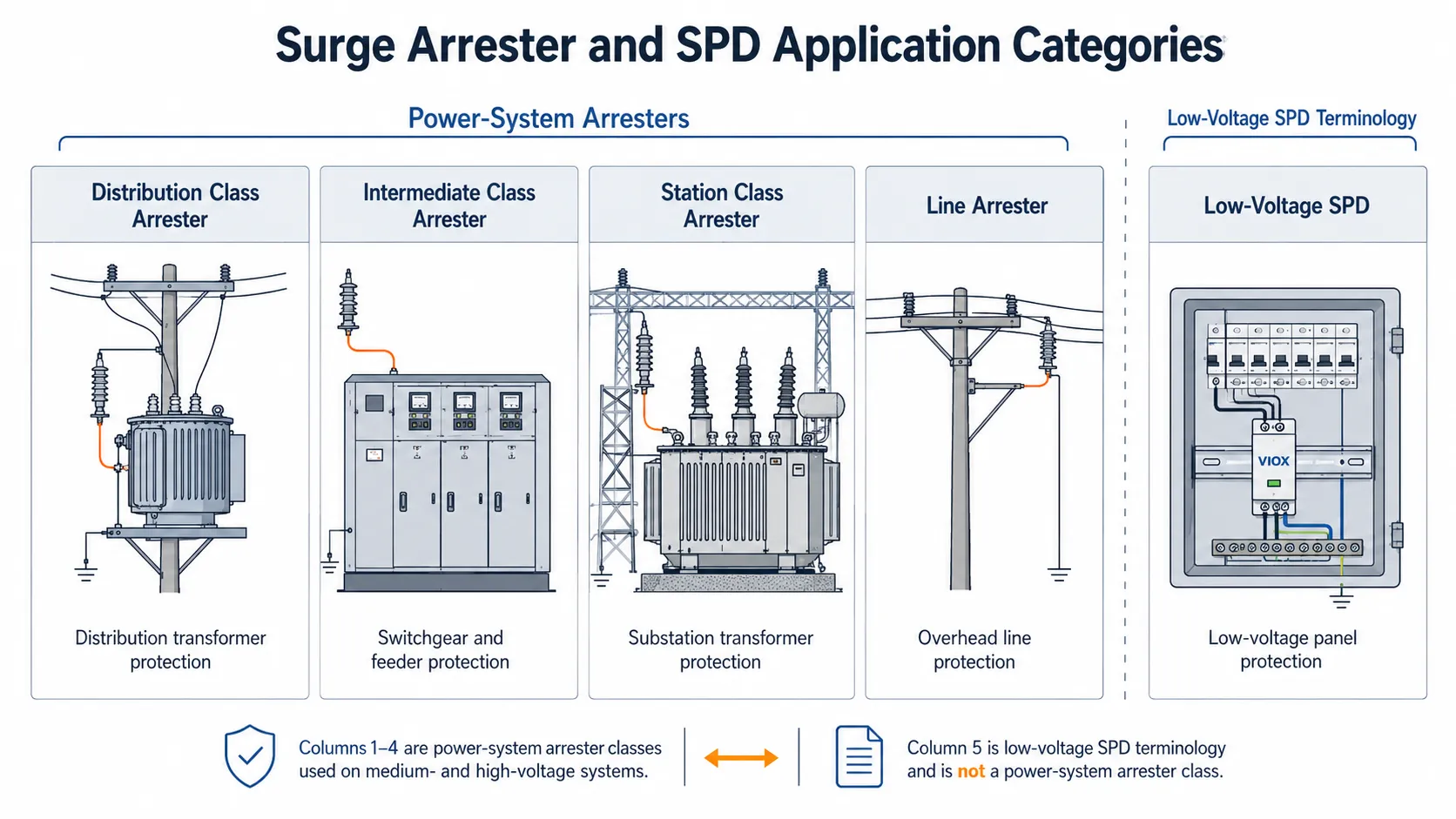
A surge arrester is an overvoltage protection device that limits transient voltage surges and diverts surge current away from protected equipment. In power distribution and utility systems, the term usually refers to medium-voltage or high-voltage arresters installed near transformers, overhead lines, substations, switchgear, and cable terminations.
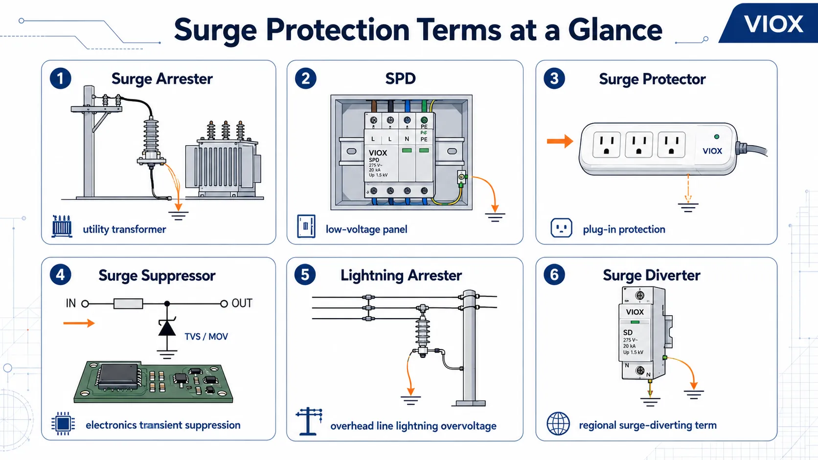
In low-voltage electrical panels, the more precise term is usually surge protective device (SPD). In everyday language, people may also say surge protector, surge suppressor, surge diverter, lightning arrester, or even the alternate spelling surge arrestor. These terms overlap, but they are not always interchangeable.
The simplest distinction is this:
Surge arrester: usually power-system overvoltage protection, often medium/high voltage.
SPD: low-voltage surge protection for panels, equipment, PV systems, data lines, and control circuits.
Surge protector: common user term, often for low-voltage plug-in or panel protection.
Lightning arrester: common or older term for an arrester focused on lightning-related overvoltage, often overlapping with surge arrester.
Quick Comparison: Surge Arrester vs SPD vs Surge Protector vs Lightning Arrester
Protect electronics or circuits from voltage spikes
Surge suppressor
General/older term, often overlaps with surge protector or SPD
Electronics, AC power, signal circuits
Product-dependent
Suppress or clamp transient voltage
Lightning arrester
Common/older term for an arrester associated with lightning overvoltage
Overhead lines, transformers, service entrances, substations
Often overlaps with surge arrester standards
Reduce lightning-induced overvoltage stress
Surge diverter
Regional/common term, often similar to surge arrester or SPD
Utility, industrial, or LV installations depending on region
Region- and product-dependent
Divert surge energy away from protected equipment
Comparison of surge arrester, SPD, surge protector, surge suppressor, lightning arrester, and surge diverter terminology and applications.
Why the Terminology Is Confusing
The confusion comes from two different worlds using similar language.
In utility and power distribution, “surge arrester” often means a device connected between a phase conductor and earth to protect insulation from lightning and switching surges. Modern power-system arresters are commonly metal-oxide, usually zinc oxide (ZnO), devices.
In low-voltage buildings and equipment, “SPD” is the more standard term. These devices are installed in distribution boards, control panels, PV combiner boxes, EV charging systems, industrial cabinets, and signal lines. They are selected by ratings such as Uc/MCOV, Up/VPR, In, Imax, Iimp, type/class, short-circuit current rating, and backup protection.
That is why a buyer searching for “surge arrester” may actually need one of three different products:
A medium-voltage arrester for a transformer, line, or substation.
A low-voltage SPD for a distribution board or control panel.
A residential whole-house surge protector, which is really a low-voltage SPD.
A surge arrester remains highly resistive at normal system voltage. When a transient overvoltage rises above its operating threshold, the arrester becomes conductive and diverts surge current toward earth. After the surge passes, it returns to a high-resistance state.
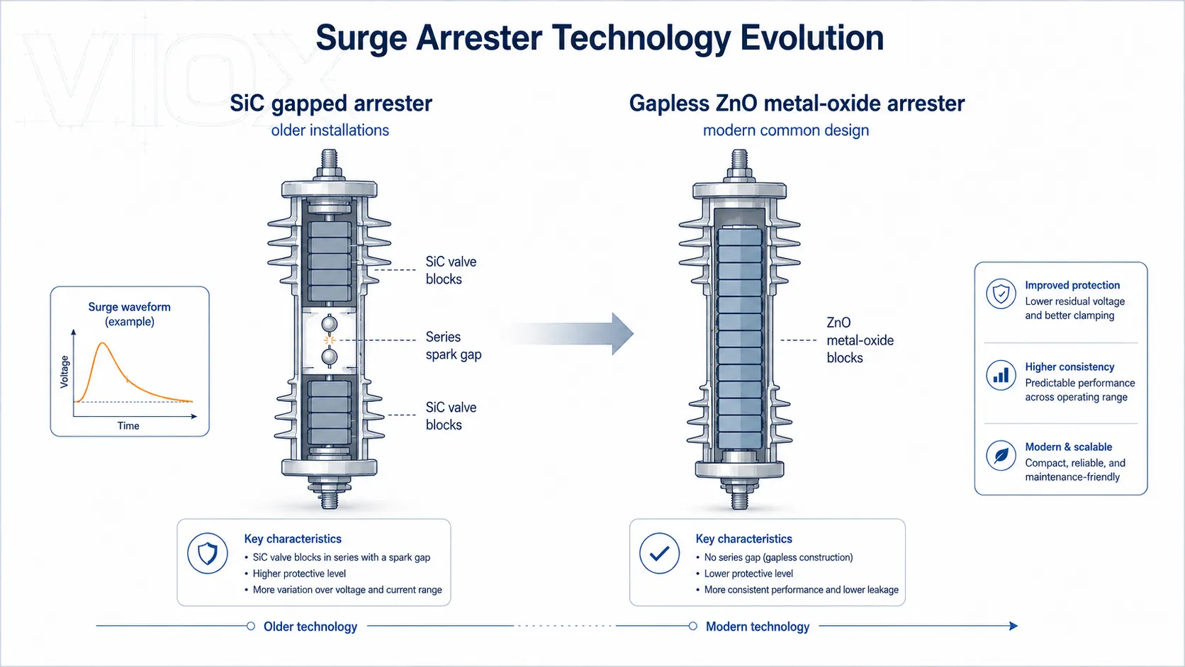
Modern arresters and many SPDs rely on metal-oxide varistor (MOV) technology, especially zinc oxide (ZnO). ZnO MOVs have a strongly nonlinear voltage-current characteristic: they conduct very little current at normal voltage, but conduct heavily during a surge.
Historical evolution from SiC gapped surge arresters to modern gapless ZnO metal-oxide arresters used in power systems and SPDs.
Historically, many power-system arresters used silicon-carbide (SiC) valve blocks with series spark gaps. These gapped SiC arresters helped limit overvoltage, but their spark gaps, aging behavior, and protection characteristics made insulation coordination more complex. Modern medium-voltage and high-voltage arresters are now commonly based on gapless metal-oxide technology, especially ZnO, because ZnO provides stronger nonlinear voltage-current behavior and can remain connected across the system without a series gap in many designs. Older installations may still contain SiC gapped arresters, so replacement projects should verify the arrester type before selecting a modern equivalent.
This matters because surge protection is not about carrying normal load current. It is about limiting a very fast transient that may last only microseconds.
Distribution board, control panel, equipment input, PV combiner box, data/control cabinet
Typical standards
IEC 60099 series, IEEE C62.11 family
IEC 61643 series, UL 1449
Typical technology
Metal-oxide arrester, often ZnO blocks
MOV, GDT, TVS, spark gap, hybrid designs
Main selection data
Rated voltage, continuous operating voltage, residual voltage, energy duty, arrester class
Uc/MCOV, Up/VPR, In, Imax, Iimp, Type/Class, SCCR, backup fuse/breaker
Main goal
Protect power-system insulation and equipment
Protect downstream low-voltage equipment and circuits
In practical terms, do not specify a “surge arrester” for a low-voltage panel unless the manufacturer uses that term for an SPD. For IEC and UL low-voltage projects, the correct engineering term is usually SPD.
Surge Arrester vs Surge Protector
“Surge protector” is a broad user-friendly term. It can mean:
a plug-in power strip with surge protection
a whole-house surge protector installed at the service panel
a panel-mounted SPD
a small electronics protection module
A surge arrester, by contrast, usually implies utility or power-distribution equipment.
Question
Better term
Protect a laptop, TV, or electronics from plug-in surges
Surge protector
Protect a residential service panel
Whole-house surge protector or Type 1/Type 2 SPD
Protect a low-voltage industrial panel
SPD
Protect a transformer or MV overhead line
Surge arrester
Protect a PV combiner box DC input
DC SPD or PV SPD
This is why search queries such as “difference between surge arrester and surge protector” often mix consumer and engineering language. A surge protector is usually low-voltage equipment protection. A surge arrester is usually power-system insulation protection.
Surge Arrester vs Surge Suppressor
“Surge suppressor” is another broad term. In electronics, it may refer to a device or component that suppresses transient voltage. In power distribution, it often overlaps with surge protector or SPD.
Use this rule:
For electrical panels and code/spec documents, use SPD.
For utility distribution and transformers, use surge arrester.
For consumer electronics, surge protector or surge suppressor may be acceptable, but check product ratings carefully.
Surge Arrester vs Lightning Arrester
In many practical conversations, surge arrester and lightning arrester overlap. A lightning arrester is usually a surge arrester intended to handle lightning-related overvoltage. However, “surge arrester” is the broader and more technically useful term because overvoltage can come from lightning, switching, faults, or system transients.
Term
Practical meaning
Lightning arrester
Common term emphasizing lightning-induced overvoltage
Surge arrester
Broader term covering lightning and other transient overvoltages
SPD
Low-voltage protection term used in modern panel and equipment applications
Do not confuse a lightning arrester with a lightning rod or air terminal. A lightning protection system intercepts and routes a direct lightning strike. A surge arrester or SPD limits transient overvoltage on electrical conductors. A complete lightning and surge protection strategy may need both.
Surge Arrester or Surge Arrestor: Which Spelling Is Correct?
The preferred technical spelling is surge arrester. The spelling surge arrestor is common in searches and informal writing, but most electrical standards, datasheets, and manufacturer documentation use arrester.
For SEO and user clarity, it is reasonable to mention both spellings:
If you are writing a technical specification, use surge arrester.
Types of Surge Arresters
Surge arrester “types” can be classified in different ways: by voltage level, duty class, installation position, or technology. For search users, the most practical classification is application-based.
Type
Typical application
What it protects
Notes
Distribution class arrester
Distribution lines and transformers
Distribution transformers, feeders, overhead networks
Common utility distribution protection
Intermediate class arrester
Applications between distribution and station duty
Transformers, substations, switchgear
Used where duty is higher than basic distribution protection
Station class arrester
Substations and major equipment
Power transformers, substation bus, switchgear
Higher-duty arrester category
Line arrester
Overhead transmission or distribution lines
Line insulation and equipment
Often used in lightning-prone routes
Riser pole / cable protection arrester
Overhead-to-underground cable transition
Cable terminations and connected equipment
Helps reduce surge stress at cable entry points
Low-voltage SPD
LV panels and equipment
Control panels, distribution boards, equipment inputs
Not usually called a traditional MV/HV arrester in IEC/UL low-voltage specs
Signal SPD
Data, telecom, control, sensor lines
Communication and control electronics
Selected by signal type, bandwidth, voltage, and grounding method
Types of surge arresters: distribution class, intermediate class, station class, line arrester, riser pole, LV SPD, and signal SPD.
This section is where many generic articles become misleading. A low-voltage SPD and a medium-voltage station arrester both limit surges, but they are not selected from the same datasheet family.
Surge Capacitor vs Surge Arrester
A surge capacitor and a surge arrester solve related but different problems.
Device
Main function
Typical use
Key limitation
Surge arrester
Clamps overvoltage and diverts surge current
Transformers, lines, substations, LV panels when using SPD terminology
Does not normally absorb long-duration overvoltage or continuous overcurrent
Surge capacitor
Reduces steep-front voltage stress by slowing voltage rise
Rotating machines, transformers, certain switching-surge applications
Does not replace an arrester for clamping high surge voltage
Surge capacitor vs surge arrester: the capacitor smooths the voltage wavefront while the arrester clamps peak overvoltage.
In some systems, surge capacitors and arresters are used together. The arrester limits peak overvoltage, while the capacitor helps reduce the steepness of the voltage wavefront. This is especially relevant where insulation stress and fast-front transients matter.
Surge Diverter vs Surge Arrester
“Surge diverter” is often used in some regions as another name for a device that diverts surge current away from protected equipment. In many low-voltage contexts, it may mean SPD. In utility contexts, it may overlap with surge arrester.
The safe interpretation is:
check the voltage level
check the product standard
check whether it is for LV panels, signal lines, transformers, or overhead power systems
compare ratings rather than relying on the name alone
Residential Surge Arrester: What Do People Usually Mean?
When a homeowner searches for “residential surge arrester,” they usually mean a whole-house surge protector or Type 1 / Type 2 SPD installed at the service equipment or distribution panel. It is not usually the same product as a utility distribution arrester mounted on an overhead line or transformer.
For residential and commercial low-voltage installations, focus on:
SPD Type 1, Type 2, or Type 3
system voltage
nominal discharge current
maximum discharge current
voltage protection level or voltage protection rating
Coordinated Protection: Surge Arrester + Type 1/2/3 SPD
High-quality surge protection is layered.
A utility arrester may protect the transformer or incoming supply equipment. A Type 1 SPD may handle high-energy surge currents at the service entrance or lightning protection boundary. A Type 2 SPD may protect distribution panels. A Type 3 SPD may protect sensitive terminal equipment close to the load. Signal SPDs may protect communication and control lines.
The purpose of coordination is to prevent one device from being overloaded and to reduce the voltage stress seen by downstream equipment.
Mistake 1: Using “surge arrester” and “SPD” as exact synonyms
They overlap in function, but not always in standard context or voltage class. In low-voltage panel specifications, SPD is usually the better term.
Mistake 2: Choosing only by kA rating
kA ratings matter, but they are not enough. For SPDs, also check Uc/MCOV, Up/VPR, In, Imax, Iimp, SCCR, backup protection, failure indication, and earthing system.
Mistake 3: Assuming a surge arrester protects against direct lightning strike damage by itself
An arrester or SPD limits transient overvoltage on conductors. Direct strike protection, bonding, earthing, external lightning protection, and coordinated SPD placement are separate parts of a full protection strategy.
Mistake 4: Ignoring the protected system voltage
A device must match the real system voltage and grounding arrangement. A low-voltage SPD cannot be substituted for a medium-voltage arrester, and a utility arrester cannot be installed like a panel SPD.
Mistake 5: Forgetting signal and communication lines
Power SPDs do not protect Ethernet, RS485, sensor, telecom, or control lines unless those lines also have suitable surge protection. Many surge failures enter through communication or control wiring.
Final Answer
A surge arrester is usually a power-system device used to protect transformers, overhead lines, substations, switchgear, and cable terminations from transient overvoltage. An SPD is the correct modern term for low-voltage surge protection in distribution boards, control panels, equipment, PV systems, EV charging, BESS, and signal lines.
A lightning arrester is often a common or older name for a surge arrester focused on lightning-related overvoltage. A surge protector or surge suppressor usually refers to low-voltage equipment protection. The best term depends on voltage level, installation point, product standard, and application.
FAQ
Is it surge arrester or surge arrestor?
The preferred technical spelling is surge arrester. Surge arrestor is a common alternate spelling in search queries, but most standards and technical datasheets use “arrester.”
Is a surge arrester the same as an SPD?
Not always. Both limit transient overvoltage, but “surge arrester” usually refers to power-system arresters, while “SPD” usually refers to low-voltage surge protective devices under IEC 61643 or UL 1449 contexts.
What is the difference between a surge arrester and a surge protector?
A surge protector is usually a low-voltage device for electronics, plug strips, whole-house protection, or panel protection. A surge arrester usually refers to utility or power-distribution overvoltage protection.
What is the difference between a surge arrester and a lightning arrester?
Lightning arrester is commonly used for arresters that protect against lightning-related overvoltage. Surge arrester is broader and can include lightning surges, switching surges, and other transient overvoltages.
What are the main types of surge arresters?
Common power-system categories include distribution class, intermediate class, station class, line arresters, and cable protection arresters. Low-voltage systems normally use SPD terminology instead.
What is the difference between a surge diverter and a surge arrester?
In many regions, surge diverter is a common term for a device that diverts surge current. It may refer to an SPD or surge arrester depending on system voltage and product context.
What is the difference between a surge capacitor and a surge arrester?
A surge arrester clamps peak overvoltage and diverts surge current. A surge capacitor helps reduce steep-front voltage stress. In some systems, both are used together.
Can an SPD replace a surge arrester?
Only if the application is low-voltage SPD protection. An LV SPD cannot replace a medium-voltage or high-voltage arrester for transformers, overhead lines, or substations.
Does a surge arrester protect against direct lightning?
It can reduce voltage stress from lightning-induced surges on conductors, but it is not a complete direct lightning protection system by itself. External lightning protection, bonding, grounding, and coordinated SPDs may also be needed.
An AC fuse and a DC fuse perform the same basic job—opening a circuit after excessive current heats and melts the fuse element—but they are not interchangeable merely because their ampere ratings match. Use a fuse only when its marking or manufacturer documentation gives the required alternating-current (AC) or direct-current (DC) voltage rating and breaking capacity for the actual circuit.
The main engineering difference appears after the element melts. AC current passes through a natural current zero every half-cycle, which assists arc extinction. Pure DC has no periodic natural current zero, so the fuse must interrupt a potentially persistent arc while accounting for circuit voltage, available fault current, and—in many applications—the DC circuit time constant. A fuse can be AC-only, DC-only, or dual-rated. The label and datasheet, not the product’s appearance, decide which case applies.
AC Fuse vs DC Fuse: The Decision Table
Decision point
AC application
DC application
What must be verified
Current waveform
Alternating current reverses and passes through zero periodically
Pure DC maintains one polarity and has no periodic natural current zero
The current type at the fuse location—not merely the equipment’s input or output label
Arc interruption
Natural current zeros assist extinction after the element melts
The fuse construction must force the arc to cool, lengthen, divide, and extinguish without natural zero crossings
AC or DC voltage marking and manufacturer application data
Voltage rating
Use the stated AC voltage rating at or above the circuit’s applicable voltage
Use the stated DC voltage rating at or above the maximum applicable DC voltage
Separate VAC and VDC values when both are listed
Breaking capacity
Must equal or exceed the prospective fault current under the stated AC conditions
Must equal or exceed the prospective fault current under the stated DC conditions
AC and DC breaking-capacity entries may differ
Circuit dynamics
Frequency, power factor, source impedance, and fault duty may matter
Source energy and inductance-to-resistance ratio can change current rise and interruption duty
Manufacturer limits and test basis for the intended circuit
Time-current behavior
Use the curve supplied for the exact fuse family and AC duty
Use the applicable DC curve or manufacturer confirmation where AC and DC behavior differ
Curve type, test conditions, preloading, ambient, and tolerance
Physical construction
May use ceramic bodies, fillers, multiple elements, arc plates, or other features
May use similar features, sometimes arranged differently for the DC duty
Do not classify the fuse by size, body material, or filler alone
Substitution
Accept only when the candidate has suitable AC data
Accept only when the candidate has suitable DC data
Exact catalog number, not a visually similar fuse
The practical rule is short: match the fuse to the current type, voltage, fault current, operating requirement, and published application conditions. A current rating by itself answers none of the interruption questions.
Why DC Arc Interruption Is More Demanding
A fuse does not finish operating at the instant its element melts. Melting creates a gap, but current may continue through an electrical arc inside that gap until the fuse extinguishes the arc and withstands the recovery voltage.
In an AC circuit, instantaneous current naturally reaches zero every half-cycle. This does not make AC interruption automatic or make every AC fuse simple: system voltage, fault current, power factor, fuse construction, and test standard still matter. It does, however, provide repeated opportunities for the arc to extinguish.
In a pure DC circuit, current does not periodically pass through zero. The fuse must create the conditions that drive the arc current to zero. Depending on the fuse design, those conditions may involve a longer arc path, multiple element restrictions, arc division, cooling surfaces, or granular filler. These are design possibilities, not a visual checklist. Industrial AC fuses can also be filled and current-limiting, while some low-voltage DC fuses are compact. “Sand-filled,” “ceramic,” or “longer” does not by itself prove a DC rating.
The DC time constant changes the duty
DC fault current does not always rise instantly. Circuit inductance resists the change in current. For a simple resistive-inductive circuit, the time constant is:
τ = L / R
where L is inductance and R is resistance. A larger L/R value means a slower current rise and more stored magnetic energy for the fuse to manage during interruption. Eaton’s Bussmann high-speed fuse guidance explains that DC voltage capability and fuse behavior can depend on this time constant; it also shows why an AC-to-DC rating cannot be derived from one universal percentage.
Use the fault-condition time constant when the manufacturer requires it. The normal operating time constant may not represent the circuit after a short circuit, and battery, traction, converter, and large DC-drive systems can present materially different source behavior.
The Four-Proof Test for AC/DC Interchangeability
Treat interchangeability as an evidence check. A candidate fuse passes only when all four proofs are available for the exact catalog number.
Proof 1: Correct current type and voltage rating
Read the voltage marking and datasheet literally:
250 VAC establishes an AC rating only unless separate DC data is published.
125 VDC establishes a DC rating only unless separate AC data is published.
250 VAC / 125 VDC is a dual rating with two distinct limits; it does not mean 250 V is permitted for both.
A plain voltage value without a clear AC/DC basis requires the manufacturer’s documentation and the governing product-marking rules to be checked.
The fuse’s voltage rating must be at least the maximum applicable circuit voltage for the stated current type. Do not convert RMS AC voltage to DC voltage using a homemade equivalence rule. Voltage waveform is only one part of interruption performance.
Proof 2: Adequate breaking capacity at that rating
Breaking capacity—also called interrupting rating—is the prospective current that the manufacturer states the fuse can safely interrupt under defined conditions. It is different from the fuse’s normal current rating.
A 20 A fuse, for example, may be installed in a circuit capable of delivering fault current many times greater than 20 A. The selected fuse therefore needs both:
a current rating and time-current characteristic suitable for the load and protected conductors or equipment; and
a breaking capacity that is not less than the prospective fault current at its installation point, under the applicable AC or DC test basis.
Do not assume the AC breaking capacity also applies to DC. If the datasheet publishes separate values, use the value for the actual circuit. If it publishes no DC value, obtain written manufacturer application guidance or select a fuse with documented DC capability.
Proof 3: Suitable operating characteristic
Matching voltage and breaking capacity does not complete the selection. The fuse must carry normal load and intended transient current while operating within the time required to protect the circuit.
Verify the exact fuse family’s:
time-current curve and whether it shows minimum melting, average melting, or total clearing;
pre-arcing and total-clearing I²t where equipment energy withstand matters;
peak let-through data in the current-limiting region;
utilization category or fuse class;
ambient-temperature, preloading, cyclic-duty, and fuseholder conditions.
AC and DC time-current behavior may converge in some longer-duration regions, but that observation does not establish DC interruption capability. Use the curve and application notes supplied for the intended duty.
Proof 4: Application and installation conditions
Confirm the conditions that can invalidate an otherwise promising rating:
DC L/R time constant and source configuration;
battery or capacitor energy;
converter or regenerative-drive topology;
minimum and maximum prospective fault current;
fuseholder voltage, current, temperature, and breaking-duty compatibility;
required standard, approval, and market documentation;
enclosure temperature, ventilation, altitude, and cyclic loading where the manufacturer treats them as selection variables.
The fuseholder is part of the installed protection system. A correctly rated fuse-link in an unsuitable holder is not a valid assembly. The fuse-link versus fuse terminology guide explains the distinction between the replaceable link and the complete fuse device.
Can an AC Fuse Be Used in a DC Circuit?
Not on the basis of its AC marking or equal ampere rating. An AC-rated fuse may be used in a DC application only when the manufacturer provides a DC rating or application data covering the intended system conditions.
Consider a cartridge fuse marked 250 VAC with no visible DC value. Even if the target circuit is only 48 VDC and the ampere rating appears correct, the marking alone does not prove that the fuse can interrupt the available DC fault current. The next step is not to apply a fixed derating percentage; it is to find the exact catalog datasheet or obtain manufacturer confirmation.
Some manufacturer engineering guides describe limited ways to evaluate particular AC fuse families in defined DC circuits. Those procedures can depend on DC voltage, minimum short-circuit current, time constant, and circuit topology. They are product-family engineering methods, not general permission to convert any AC fuse to DC service.
Can a DC Fuse Be Used in an AC Circuit?
Do not assume that a DC marking automatically supplies an AC rating. The fuse may be physically capable of interrupting a particular AC duty, but procurement and design approval require published evidence for that use.
If the fuse carries both AC and DC ratings, evaluate the AC circuit against the AC values. If it carries only a DC rating, check the manufacturer documentation rather than treating DC service as a universal “more demanding” certification that automatically covers AC. Test methods, voltage definitions, breaking capacities, utilization categories, and approvals are not interchangeable labels.
How to Read AC-Only, DC-Only, and Dual Ratings
Documentation found
Decision
Required next action
AC voltage and AC breaking capacity only
AC-only for the evidence available
Use within the AC ratings or request separate DC application data
DC voltage and DC breaking capacity only
DC-only for the evidence available
Use within the DC ratings or request separate AC application data
Separate AC and DC voltage and breaking-capacity values
Dual-rated candidate
Check each circuit against its own values and operating conditions
One voltage marking but unclear current type
Unverified
Resolve the marking through the exact datasheet or manufacturer
Correct voltage but no adequate breaking-capacity evidence
Reject or keep provisional
Determine prospective fault current and obtain matching interruption data
Correct ratings but wrong physical system or utilization category
Not interchangeable
Select the correct fuse-link and holder system
A dual-rated fuse is not a universal fuse. Its AC and DC limits can differ, and the same catalog number may have different breaking capacities or application notes for each current type. Record the data separately in the bill of materials or substitution review.
Why Fixed AC-to-DC Conversion Rules Fail
Rules such as “halve the AC voltage rating for DC” may resemble a value published for one product family, but they are unsafe as general selection rules. Eaton notes that, for many high-speed fuses, the DC rating can be lower than the AC rating and can decrease as time constant increases; the same guide also describes special conditions where DC capability may behave differently. That is precisely why the manufacturer’s defined method must replace a universal ratio.
The following shortcuts are not acceptable evidence:
Shortcut
Why it fails
Correct evidence
Same ampere rating
Ampere rating does not establish arc-interruption capability
AC/DC voltage and breaking-capacity data
DC voltage is lower than the AC marking
A lower number alone does not prove DC interruption
Published DC rating or application method
The DC fuse is longer
Dimensions do not reveal tested duty
Catalog number and datasheet
Both fuses contain quartz filler
Construction features are not ratings
Marking, test basis, and manufacturer data
The holder accepts the fuse
Mechanical fit does not prove electrical compatibility
Complete fuse-link/holder system verification
A similar series has a DC rating
Ratings do not transfer between families or variants
Exact part-number documentation
Three Application Checks
1. Replacing an AC-only fuse in a control circuit
If the original and replacement both show the required AC voltage, current rating, breaking capacity, operating characteristic, and physical-system compatibility, the comparison can proceed on the AC data. A higher DC rating on one candidate does not compensate for a missing AC class, curve, or approval required by the equipment design.
2. Using a dual-rated fuse in an AC and a DC product variant
Treat the two variants as separate applications. For the AC product, record the VAC and AC breaking-capacity entries. For the DC product, record the VDC and DC breaking-capacity entries plus any permitted time constant or circuit restrictions. Do not copy one completed evaluation across both variants.
3. Protecting PV or battery circuits
The AC/DC comparison is only the first gate. Photovoltaic (PV) strings can require gPV fuse-links and application evidence within the scope of IEC 60269-6; battery systems can present high available fault current and significant stored energy. Use the DC fuse breaking-capacity guide for PV systems for the fault-duty question and the 12 V fuse-sizing guide for low-voltage conductor and load inputs. Do not import a universal multiplier from one market or application into another.
For broader utilization categories and IEC fuse-system selection, use the IEC 60269 fuse guide. The comparison page determines AC/DC suitability; it does not replace the complete sizing and coordination process.
AC/DC Fuse Replacement Record
Use this table for design review, maintenance substitution, or an RFQ.
The VIOX electrical fuse guide provides the broader selection map. When the application requirements are defined, review the available VIOX low-voltage fuse and holder families or send the circuit voltage, AC/DC duty, normal current, transient profile, prospective fault current, fuse class, required operating time, holder format, and DC time constant where applicable to [email protected].
A fuse holder is not selected by current rating or physical fit alone. Choose the fuse-link and fuse system first, then verify that the holder accepts the exact fuse dimensions and contact format, is rated for the system voltage and AC/DC duty, carries the circuit current under the actual thermal conditions, matches the mounting and conductor arrangement, and provides the required touch and environmental protection.
A basic fuse holder is also not automatically a load-break switch or an isolator. If personnel must operate the device under load or use it as a defined isolation point, specify equipment with that function and the corresponding rating.
Fuse Holder Types at a Glance
The most useful way to classify fuse holders is by how they are mounted and serviced.
Fuse holder type
Best suited to
Main advantage
Critical checks
DIN-rail modular holder
Control panels, distribution boards, PV and industrial cabinets
Equipment with a replaceable fuse accessible from an enclosure wall
Fuse replacement without opening the equipment
Panel cutout, rear terminal protection, cap/carrier retention, IP rating
In-line holder
Cable harnesses, localized protection, mobile and retrofit circuits
No PCB or panel space required
Wire size, termination method, strain relief, sealing, fuse format
PCB holder or fuse clips
Power supplies, controllers and electronic assemblies
Compact, direct board integration
Footprint, solder process, creepage/clearance, heat around the fuse
Fuse base or fuse block
Industrial power distribution and higher-current fuse systems
Robust mounting and conductor termination
Exact fuse system, contact arrangement, conductor size, barriers and safe service method
This table identifies the mechanical family only. It does not prove that a holder is suitable for a particular circuit.
What a Fuse Holder Does
A fuse holder provides the mechanical support, electrical contacts, terminals and, where applicable, a carrier or cover for a replaceable fuse-link. During normal operation, the complete current path includes the conductors, terminals, holder contacts and fuse-link. Every connection contributes resistance and heat.
When the fuse-link operates, it interrupts the overcurrent. The holder must remain suitable for the electrical, thermal and mechanical stresses assigned to it, but the holder does not replace the fuse-link’s time-current characteristic, utilization category, breaking-capacity evidence or energy-limiting data.
Removing a carrier or pulling a fuse can expose personnel and equipment to an arc or energized parts if the circuit is still carrying current. A holder may be finger-safe or withdrawable yet still lack a load-break rating.
If the application requires routine switching, visible isolation, interlocking or lockout/tagout, verify a defined disconnecting function rather than inferring it from appearance. The decision is covered in Fuse Holder vs Fuse Switch Disconnector.
Five Main Types of Fuse Holders
1. DIN-Rail Modular Fuse Holders
DIN-rail holders are common in industrial control panels, distribution assemblies, automation cabinets and photovoltaic (PV) combiner boxes. Their modular form supports consistent panel layout, and many designs provide front access, multi-pole configurations or status indication.
They are not interchangeable simply because they occupy the same DIN-rail width. Check:
exact fuse-link dimensions and contact system;
rated operational voltage and explicit AC or DC suitability;
number of poles and whether all required conductors are protected or disconnected;
terminal conductor range, preparation and tightening instructions;
permissible power dissipation or temperature-rise conditions;
touch protection with the carrier inserted and, where specified, removed;
indication circuit behavior and leakage, if an indicator is fitted.
For PV applications, confirm that the fuse-link, holder and assembly are intended for the DC system voltage and prospective fault conditions. A generic AC modular holder is not made suitable for PV merely by installing a PV fuse-link.
2. Panel-Mount Fuse Holders
Panel-mount holders pass through an enclosure wall and typically allow a cartridge fuse to be replaced from the front. They are useful in instruments, power supplies, machinery and equipment that should remain closed during normal fuse replacement.
Selection depends on more than the cartridge size. Verify the permitted panel thickness and cutout, cap or carrier design, rear terminal guards, accessibility of live parts, mounting orientation and the environmental rating of the complete installed assembly. An IP rating stated for a holder may depend on the correct gasket, cap and panel installation.
3. In-Line Fuse Holders
An in-line holder is installed directly in a conductor or wiring harness. It is useful when protection must be located close to a source or load and no rail, panel opening or PCB is available.
The cable interface is often the limiting issue. Match the conductor cross-section, insulation diameter, crimp or splice method, strain relief, flexing duty and sealing requirement. A waterproof-looking cap does not establish an ingress-protection rating; use the manufacturer’s tested rating and installation instructions.
Locate the holder where it can be inspected and replaced without pulling on the cable. In battery and DC systems, place overcurrent protection according to the applicable installation rules and the source’s fault-current capability.
4. PCB Holders and Open Fuse Clips
PCB fuse holders include enclosed carriers, open clips, through-hole parts and surface-mount designs. They minimize wiring but transfer thermal, spacing and assembly decisions to the board design.
The board designer must consider:
fuse footprint and retention;
copper area and trace current capacity;
creepage and clearance at the system voltage;
heat from the fuse-link, contacts and nearby components;
soldering process compatibility;
accessibility and protection against accidental contact;
vibration and mechanical loading during fuse replacement.
Open clips make inspection easy but expose the fuse and contacts. They are normally suitable only where access is controlled by the equipment enclosure.
5. Fuse Bases and Blocks for Industrial Power Distribution
Industrial fuse systems may use a fixed base, separate carrier, knife-blade contacts or cylindrical fuse clips. They are selected as a coordinated mechanical and electrical system, not as a generic holder for any fuse with a similar current marking.
NH knife-blade and cylindrical fuse systems differ in contact geometry, size, servicing method and application range. Use NH Fuse vs Cylindrical Fuse when deciding between those formats.
For higher-current systems, verify conductor connection, barriers, phase spacing, installation orientation, available accessories, safe replacement method and the documentation for the complete fuse system. Do not assume that a large open fuse base may be operated under load.
How to Select a Fuse Holder: Eight Engineering Checks
Step 1: Select the Fuse-Link and Fuse System First
Start with the protection study. Determine the required fuse utilization category or class, time-current behavior, rated voltage, rated current, breaking capacity and any required current-limiting or I²t performance. Then identify the exact fuse size and contact format.
The holder cannot correct an incorrectly selected fuse-link. Conversely, a correct fuse-link can still overheat or become unsafe in an incompatible holder.
Record at least:
fuse standard and category or class;
manufacturer series or standardized fuse system;
body dimensions and terminal/contact format;
fuse-link rated current and voltage;
power dissipation data where provided;
required accessories, striker or indication interface.
Step 2: Verify Physical Compatibility
The fuse must seat fully, contact the intended surfaces and be retained with the designed contact pressure. Similar body dimensions do not guarantee compatibility.
Check the datasheet for:
accepted fuse-link designation and size;
cylindrical diameter and length, or blade/tag geometry;
rejection features that prevent the wrong fuse class or rating;
carrier, cap and adapter part numbers;
approved combinations rather than visual similarity.
Adapters and reducers should be used only when they are part of a documented system. Improvised metal spacers or modified contacts can increase resistance, weaken retention and defeat rejection features.
Step 3: Match Voltage and AC/DC Duty
The holder’s rated voltage must be at least the circuit voltage and must apply to the actual current type. Also check the manufacturer’s conditions of acceptability, insulation coordination and installation spacing.
Do not apply a vague safety margin or assume that a high AC marking automatically covers the same DC voltage. DC current does not have a natural current zero every half-cycle, and the complete fuse system must be documented for the intended DC duty.
The holder voltage marking alone also does not prove that the final panel has adequate creepage, clearance or enclosure spacing.
Step 4: Coordinate Circuit Current, Fuse Current and Holder Heating
Three different currents must not be confused:
the normal circuit current;
the fuse-link rated current chosen from the load and time-current study;
the fuse-holder maximum current rating under stated conditions.
The fuse-link may be intentionally rated above normal circuit current to tolerate inrush. That does not permit the circuit current or thermal loading to exceed the holder’s limits.
Holder heating depends on contact resistance, terminal resistance, fuse-link power dissipation, conductor size, enclosure temperature, airflow, grouping and installation orientation. A rating established with a standardized test link may not reproduce the heat generated by the selected production fuse-link.
Use the manufacturer’s temperature-rise, power-dissipation and derating information for the exact combination. There is no responsible universal percentage that applies to every holder.
Step 5: Check Fault-Current and Complete-System Documentation
The prospective short-circuit current at the installation point must be within the capability of the specified protection system. The fuse-link’s breaking capacity is not a free-standing rating for every holder that it can physically enter.
Depending on the market and product category, documentation may state a short-circuit current rating, conditions of acceptability, tested fuse combinations or restrictions on enclosure and conductor arrangement. Evaluate the exact fuse-link/holder combination and the final equipment standard.
Do not describe the holder as “current limiting” unless the documentation assigns that behavior to the complete combination. Current limitation is primarily established by the fuse-link’s performance under the relevant test conditions.
Step 6: Match Mounting, Poles and Terminals
Choose the physical type from the equipment architecture:
DIN rail for modular panel construction;
panel mount for external service access;
in-line for harness or localized protection;
PCB for board-level protection;
industrial base/block for larger fuse systems.
Then verify pole count, rail or panel dimensions, conductor entry direction, conductor material, terminal range, stripping length, ferrule or lug requirements and manufacturer tightening instructions.
The terminal must accept the actual conductor without trimming strands, doubling conductors without approval or placing insulation inside the contact zone.
Step 7: Define Access, Indication and Switching Requirements
Ask who will replace the fuse, whether energized parts can be reached, and whether the device will ever be operated while current is flowing.
Relevant features include:
finger-safe or dead-front construction;
carrier retention and tool requirements;
fuse-status indication;
auxiliary contacts or remote signaling;
lockable operating mechanism;
load-break or isolation rating, when genuinely required.
An indicator may use a small sensing current across an open fuse. Confirm its voltage range and whether leakage is acceptable for the connected load or control input.
Step 8: Verify the Environment
Define the real environment rather than selecting an indoor holder by catalog appearance. Consider:
ambient temperature inside the operating enclosure;
airflow and grouping with adjacent heat sources;
dust, condensation, washdown or immersion;
UV exposure and outdoor aging;
salt, chemicals and corrosive gases;
vibration, shock and cable movement;
altitude where it affects insulation or cooling.
Use a documented ingress-protection rating only for the complete installed condition to which that rating applies. If the holder relies on the panel or outer enclosure for protection, include that boundary in the specification.
How to Read Fuse Holder Ratings
Datasheet field
What it tells you
What it does not prove
Accepted fuse type/size
Physical and system compatibility
Correct fuse selection for the load
Rated voltage
Maximum application voltage under stated conditions
Suitability for both AC and DC unless both are stated
Rated current
Holder current limit under defined test conditions
Acceptable temperature rise in every enclosure
Power acceptance/dissipation
Thermal compatibility with the fuse-link
Complete panel cooling performance
Short-circuit rating or conditions
Fault-duty boundary for documented combinations
Universal use with any fuse that fits
Terminal range
Permitted conductor sizes and forms
Permission to use multiple conductors or unlisted lugs
IP rating
Tested ingress protection in a defined configuration
Protection if seals, caps or mounting conditions change
Pole count
Number of current paths in the assembly
Which conductors must be fused or switched in a given system
Indicator rating
Operating range of a status indicator
Zero leakage or compatibility with every PLC input
Standard/certification reference
Evaluation framework for that product
Compliance of the complete panel or machine
Treat catalog data as a set of conditions, not a list of independent numbers. If the datasheet does not identify the fuse combination, test basis or installation conditions needed for your application, request the manufacturer’s technical file before specification.
Application Decisions
Industrial Control Panel
A DIN-rail modular holder is usually the practical starting point for branch control circuits because it integrates with terminal blocks and modular equipment. Selection still requires the exact cartridge size, circuit voltage, fault-current documentation, terminal range, panel temperature and touch-safety requirement.
If operators need to isolate a branch by opening the fuse device, specify a fuse switch-disconnector with the required operational rating rather than treating a pull-out holder as a switch.
PV Combiner Box
PV strings require a fuse-link and holder explicitly suitable for the maximum DC system voltage and environmental conditions. Confirm polarity-independent or polarity-specific behavior where applicable, conductor temperature, enclosure heating, outdoor protection and service procedure.
PCB clips or panel-mount miniature holders are common. The main risks are insufficient spacing, board heating, incorrect cartridge size and unsafe user access. IEC 60127-6:2023 specifically covers holders for miniature fuse-links within its stated scope; it should not be used as a generic standard for industrial fuse systems covered elsewhere.
Wiring Harness or Mobile Equipment
An in-line holder can place protection close to the source without a panel. Match the blade or cartridge format, conductor cross-section, crimp tooling, sealing, strain relief, temperature and vibration duty. A holder hanging from unsupported wires is a mechanical failure waiting to develop.
Industrial Feeder or High-Current Distribution
Use the standardized fuse system and its documented base or block. Evaluate busbar or cable terminations, barriers, phase spacing, authorized-person access and the method for safe fuse replacement. The holder should be treated as part of the power-distribution assembly, not as an isolated accessory.
Common Fuse Holder Selection Mistakes
Selecting by Ampere Marking Alone
The same current marking can appear on products with different fuse formats, voltage duties, terminals, thermal conditions and standards. Current is only one input.
Assuming That a Fuse Which Fits Is Compatible
Physical insertion does not prove contact pressure, rejection-system compliance, power-dissipation compatibility or fault-duty suitability.
Using the Fuse Holder as a Routine Switch
A removable carrier is not evidence of load-break capability. De-energize according to the equipment instructions unless the product is explicitly rated for the intended switching duty.
Ignoring Enclosure Temperature
The air inside a compact panel can be much hotter than the room. Adjacent power devices, grouped holders and limited airflow can raise terminal and contact temperatures even when the circuit current appears acceptable.
Treating AC and DC Ratings as Interchangeable
Use the exact AC or DC marking and the approved fuse combination. Do not transfer an AC rating to a DC system by assumption.
Reusing Heat-Damaged Components
Discoloration, softened plastic, weak fuse retention, pitted contacts or burnt insulation indicate that the current path has been compromised. Replacing only the fuse-link does not repair the holder or terminal.
Inspection and Replacement Triggers
Inspection must be performed under an electrically safe work condition and according to the equipment manufacturer’s procedure. Look for:
discoloration, odor, deformation or melted material;
loose, corroded or contaminated contacts;
weak carrier retention or mechanical damage;
damaged seals, caps or touch guards;
conductor insulation pulled into the terminal or exposed strands;
abnormal temperature difference compared with equivalent loaded poles;
repeated fuse operation without a confirmed circuit fault.
Do not clean, bend or retension contacts unless the manufacturer permits that service action. Replace the holder when heat or mechanical damage has altered the contact system or insulation. After replacement, investigate the load, fuse selection, conductor preparation, terminal torque and enclosure temperature so the failure is not repeated.
Fuse Holder RFQ Checklist
Send the following information when requesting a fuse holder quotation or technical review:
Applicable IEC, UL or equipment standard.
Exact fuse-link manufacturer, series, size, class/category and rated current.
System voltage, AC/DC, frequency where relevant and grounding arrangement.
Normal circuit current, load type and inrush profile.
Prospective short-circuit current at the installation point.
Mounting type, pole count and available panel or PCB space.
Conductor material, cross-section, quantity and termination type.
Maximum enclosure ambient temperature, grouping and airflow.
Required IP, UV, corrosion, vibration or altitude conditions.
Touch-safety, indication, auxiliary-contact, switching or isolation requirements.
Required certification documents, test reports and approved fuse combinations.
VIOX supplies low-voltage fuses and fuse-holder solutions for industrial and electrical-distribution applications. Review the VIOX fuse product range or send the completed checklist to [email protected] for a model-level review. Final selection must be verified against the relevant datasheet and equipment standard.
Frequently Asked Questions
What are the main types of fuse holders?
The main mounting types are DIN-rail modular, panel-mount, in-line, PCB/open-clip and industrial fuse base or block designs. Within each group, the accepted fuse system, voltage, AC/DC duty, current, terminals and environmental protection still have to be verified.
Should the fuse or the fuse holder be selected first?
Select the fuse-link from the protection requirements first, then select a holder approved for that exact fuse system and suitable for the circuit and installation. In some designs the available holder can constrain the fuse choice, so both must be checked before the design is frozen.
Can a fuse holder have a lower current rating than the fuse?
The normal circuit current must not exceed the holder’s permitted current under the stated conditions. A fuse-link can sometimes have a higher ampere rating than the normal load to tolerate inrush, but the combination requires a thermal check using the exact fuse power dissipation and holder guidance. Physical compatibility alone is insufficient.
Can an AC fuse holder be used for DC?
Only when the manufacturer explicitly rates the holder and the selected fuse combination for the required DC voltage and application. Do not infer a DC rating from an AC marking.
Is a fuse holder a disconnect switch?
Not automatically. Use it as a switching or isolation device only when the product has the required load-break or disconnecting rating and the installation follows its instructions. Otherwise, de-energize the circuit before removing the carrier or fuse-link.
What causes a fuse holder to overheat?
Common causes include loose or contaminated contacts, incorrect conductor preparation, insufficient terminal torque, a damaged carrier, excessive circuit current, high fuse-link power dissipation, grouping and high enclosure temperature. The fault must be corrected before the holder is returned to service.
An MCB is a circuit breaker. More precisely, MCB means miniature circuit breaker, so it identifies one product class within the wider circuit-breaker family. The two terms are not parallel alternatives: every MCB is a circuit breaker, but not every circuit breaker is an MCB.
Use circuit breaker when discussing the whole category. Use MCB when the compact, usually modular device class and its applicable product standard, ratings, and trip characteristics have actually been established. A matching ampere label alone does not make an MCB interchangeable with another breaker.
Circuit Breaker vs MCB at a Glance
Question
Circuit breaker
MCB
What does the term mean?
An umbrella term for automatic switching devices designed to interrupt a circuit under specified abnormal conditions
Miniature circuit breaker: one defined product class within that umbrella
Does the name identify one construction?
No. It can refer to multiple breaker families, sizes, operating mechanisms, trip systems, and voltage classes
More specific, but the name still does not establish every rating or approval
Common low-voltage context
May refer to an MCB, MCCB, ACB, or another breaker type
Commonly used in final distribution and similar compact modular applications
Are trip settings adjustable?
Cannot be answered from the generic term
Common MCB designs use manufacturer-defined trip characteristics; verify the exact product
Can the name prove suitability?
No
No. Check the standard, voltage, current, breaking capacity, trip behavior, poles, terminals, and installation system
The most important difference is therefore classification, not a universal ratings contest. “Circuit breaker” is a category; “MCB” is a more specific member of that category.
The Circuit-Breaker Family in One Map
In low-voltage distribution, several familiar labels sit under the circuit-breaker umbrella:
MCB — miniature circuit breaker: compact overcurrent protection commonly used for final circuits and modular distribution assemblies.
MCCB — molded-case circuit breaker: a molded-case family used across many distribution and equipment applications, often with a wider choice of frames, trip units, accessories, and coordination options.
ACB — air circuit breaker: a low-voltage breaker family commonly applied at main or large distribution levels where its documented ratings and functions suit the system.
Other breaker families: application- and market-specific products may use other construction, protection, or installation classifications.
These labels describe product families; they are not a complete specification. The applicable standard and exact manufacturer declaration remain essential.
For example, IEC 60898-1:2015 with Amendment 1:2019 covers specified AC air-break circuit breakers for household and similar installations, within the voltage, current, and short-circuit-capacity limits stated in its scope. IEC 60947-2:2024 covers low-voltage circuit breakers intended for installation and operation by instructed or skilled persons within its stated voltage scope. These standards overlap in everyday conversation but are not interchangeable labels.
Why “Circuit Breaker vs MCB” Sounds Like a Product Comparison
In everyday use, people often say “circuit breaker” when they mean a physically larger breaker, especially an MCCB. That creates a false comparison:
circuit breaker versus MCB
The technically clearer comparison is usually one of these:
MCB vs MCCB when comparing two low-voltage breaker families;
MCB vs ACB when comparing final-distribution and main-distribution product families;
one exact MCB vs another exact breaker when replacing a device in a real assembly.
This distinction matters in purchasing and engineering. A request for “a 32 A circuit breaker” leaves unanswered whether the project needs an MCB, MCCB, equipment-specific breaker, AC or DC product, particular trip behavior, a required interrupting rating, or compatibility with a specific panel system.
For a direct product-family comparison, see MCB vs MCCB. This page intentionally does not repeat that guide.
What Actually Makes an MCB More Specific?
Calling a device an MCB narrows the field, but only partly. In an IEC-style application, the product marking and documentation may identify:
the declared product standard;
rated current and rated voltage;
AC or DC suitability;
time-current characteristic or instantaneous pickup designation;
rated short-circuit capacity;
number and function of poles;
terminal conductor range, tightening requirements, and compatible busbar system;
isolation, accessories, environmental limits, and approvals where declared.
None of these fields should be inferred from the word miniature. MCBs from different standards, series, or markets can use different markings and qualification rules.
Likewise, the generic phrase circuit breaker says nothing reliable about physical size, available adjustments, service conditions, breaking capacity, or installation method. Those properties belong to the selected product—not to the umbrella noun.
Can Another Circuit Breaker Be Replaced with an MCB?
Not from the category name or current rating alone. A replacement is defensible only when the exact device, assembly, and installation requirements have been checked.
Use these six gates:
Governing standard and market — Confirm the required product standard, certification or listing, destination market, and any assembly-level conditions.
System voltage and current type — Verify rated operational voltage, frequency, AC or DC suitability, and any polarity requirements.
Current and conductor coordination — Select the protective rating and trip behavior for the conductors, load, ambient conditions, grouping, and applicable design rules.
Short-circuit duty — Confirm that the declared breaking capacity is suitable for the prospective short-circuit current at the installation point. Do not choose 6 kA or 10 kA from the load current.
Trip behavior and coordination — Check starting or inrush current, time-current behavior, upstream/downstream selectivity, and any manufacturer-tested backup combination.
Physical and functional compatibility — Verify poles, neutral treatment, mounting, terminals, busbar fit, enclosure or panel approval, accessories, isolation function, and exact dimensions.
If any gate is unknown, a same-ampere MCB should not be treated as an approved substitute. Obtain the prospective fault-current information, assembly documentation, and manufacturer data before selecting the device. Installation and replacement should be performed by a qualified person under the applicable local rules.
Use the Right Owner for the Next Decision
This page owns one question: how an MCB relates to the circuit-breaker category. Use the more specific VIOX guide for the next engineering task:
When the application requirements are known, review the VIOX MCB product range and request the exact series data needed for the destination market and assembly.
Frequently Asked Questions
Is an MCB the same as a circuit breaker?
An MCB is a type of circuit breaker. In casual conversation, the terms may refer to the same installed device, but they are not equal as category labels: circuit breaker is broader than MCB.
Is every residential circuit breaker an MCB?
No. Product construction, terminology, standards, and panel systems vary by market. Identify the exact device and its declared standard rather than classifying it from the building type alone.
Can an MCB replace an MCCB if the ampere rating is the same?
Not on that basis alone. The standard, voltage, fault-current duty, trip characteristics, coordination, poles, mounting, terminals, accessories, and assembly approval may differ. Use the six-gate check and exact manufacturer documentation.
A 20 amp circuit can handle 2,400 watts at 120 volts or 4,800 watts at 240 volts. For continuous loads, use the 80% rule: 1,920 watts at 120V or 3,840 watts at 240V. Always match the breaker to the wire size, outlet rating, load type, and local electrical code.
The basic formula is:
Watts = Volts × Amps
Watts = Volts × Amps: the basic formula for calculating load on any circuit.
So for a 20 amp circuit:
120V × 20A = 2,400W
240V × 20A = 4,800W
But those are maximum calculated values. In real installations, a circuit breaker protects the wiring, not just the appliance. Continuous loads, conductor size, receptacle rating, voltage, and local code all affect what is safe.
20 Amp Circuit Watts Quick Table
Circuit voltage
Maximum calculated load
80% continuous load target
Common use
120V, 20A
2,400W
1,920W
General receptacles, kitchen small-appliance circuits, laundry receptacles
208V, 20A single-phase
4,160W
3,328W
Some commercial equipment circuits
240V, 20A
4,800W
3,840W
Dedicated equipment circuits, some heaters or tools
240V, 20A, 3-phase
about 8,314W
about 6,651W
Commercial and light industrial loads
20 amp circuit wattage comparison across common voltages with 80% continuous-load planning values.
For most U.S. homeowners asking about a 20 amp circuit, the answer is usually the 120V line: 2,400 watts maximum, or 1,920 watts for continuous load planning.
120V vs 240V: Why the Wattage Changes
A 20 amp breaker does not have one fixed wattage. Wattage depends on voltage.
Formula
Result
120V × 20A
2,400W
240V × 20A
4,800W
208V × 20A
4,160W
This is why “how many watts can a 20 amp breaker handle?” is incomplete unless you also know the voltage.
A single-pole 20A breaker in a typical North American residential panel usually supplies a 120V circuit. A double-pole 20A breaker usually supplies a 240V circuit. The breaker amp rating may look the same, but the available wattage is different because the voltage is different.
What Is the 80% Rule for a 20 Amp Circuit?
For continuous loads, do not plan to use the full 20 amps. A common rule is to size continuous loads at no more than 80% of the circuit rating.
For a 20 amp circuit:
20A × 80% = 16A
At 120V:
120V × 16A = 1,920W
At 240V:
240V × 16A = 3,840W
Maximum calculated load versus 80% continuous-load target for a 20 amp circuit at 120V.
This matters for loads that run for a long time, such as fixed lighting, heaters, some commercial equipment, and continuous-duty appliances. A short-use kitchen appliance is not the same as a heater running for hours.
Maximum Load vs Safe Continuous Load
Question
120V 20A circuit
240V 20A circuit
Absolute calculated maximum
2,400W
4,800W
Better planning target for continuous load
1,920W
3,840W
Current at the 80% target
16A
16A
Should you load it to the maximum all day?
No
No
A breaker may not trip immediately at exactly 20 amps. Thermal-magnetic breakers have time-current behavior. That does not mean the circuit should be used continuously at its full rating. Heat builds in conductors, terminals, receptacles, plugs, and breaker contacts.
Can a 20 Amp Breaker Run a 3000W Load?
It depends on the voltage.
Load
Current at 120V
Current at 240V
Suitable for a 20A circuit?
3,000W
25A
12.5A
Not on 120V 20A; possibly on 240V 20A if the circuit and equipment are correctly rated
2,000W
16.7A
8.3A
Usually too high for continuous 120V planning, but under 20A for short-duty use
1,500W
12.5A
6.25A
Common on 120V 20A circuits
7,200W
60A
30A
Not suitable for a 20A circuit
A 3,000 watt appliance on 120V draws about 25 amps, so it is too large for a 20 amp 120V circuit. On 240V, the same 3,000 watt load draws only 12.5 amps, so it may fit a 20 amp 240V circuit if the equipment, breaker, wire, receptacle, and installation rules all match.
How Many Volts Can a 20 Amp Breaker Handle?
A 20 amp breaker is rated by both current and voltage. The “20A” marking tells you the current rating, not the voltage rating.
To know the voltage, check the breaker label and panel application. Common examples include:
single-pole residential breakers used on 120V circuits
double-pole residential breakers used on 240V circuits
industrial or commercial breakers marked for specific AC voltage ratings
DC breakers marked separately for direct-current voltage
Do not assume a breaker can be used at any voltage just because it is rated 20A. Voltage rating affects arc interruption and safety. This is especially important when comparing AC breakers and DC breakers.
A breaker protects the circuit wiring. You should never increase a breaker size just to stop nuisance tripping.
In common North American residential wiring:
15A circuits are commonly associated with 14 AWG copper conductors.
20A circuits are commonly associated with 12 AWG copper conductors.
A 20A breaker should not be placed on wiring that is only suitable for 15A protection.
20 amp breaker safety requires matching the breaker, wire size, outlet rating, and load as one system.
The breaker, conductor, receptacle, and load must be treated as one system. If one part is undersized, the circuit can overheat even if the appliance seems to run normally.
Common Appliance Examples on a 20 Amp 120V Circuit
Appliance or load
Typical wattage range
Notes for a 20A 120V circuit
Phone charger / small electronics
under 100W
Usually low load
Laptop
45W–150W
Usually low load
Desktop computer and monitor
200W–600W
Multiple devices can add up
Microwave
900W–1,500W output, often higher input
May need a dedicated circuit depending on installation
Toaster
800W–1,500W
High load for short periods
Space heater
about 1,500W
Large share of a 20A circuit
Hair dryer
1,200W–1,875W
High load; often used near GFCI-protected areas
Portable air conditioner
varies widely
Check nameplate current, not only marketing wattage
The safest method is to read the nameplate on each appliance. Add the watts of devices that may run at the same time, then compare the total with the circuit capacity.
How to Calculate Load on a 20 Amp Circuit
Use this simple process:
Find the voltage of the circuit: usually 120V or 240V.
Find the appliance wattage or current from the nameplate.
Convert current to watts if needed: Watts = Volts × Amps.
Add the loads that can operate at the same time.
Compare the total with the circuit limit.
For continuous loads, compare with the 80% planning value.
Example:
Device
Watts
Space heater
1,500W
Desktop computer setup
400W
Lighting
150W
Total
2,050W
On a 120V 20A circuit, 2,050W is below the calculated maximum of 2,400W, but above the 1,920W continuous-load planning value. If the space heater runs for long periods, this is not a good load plan.
Why a 20 Amp Breaker Trips Before You Expect
A 20 amp breaker can trip even when your quick math looks acceptable. Common reasons include:
several high-wattage appliances running at the same time
motor, compressor, pump, or transformer inrush current
loose receptacle or terminal connections
damaged plugs or cords
old or weak breaker mechanism
shared loads on the same branch circuit
heat buildup inside the panel or outlet box
a ground fault or arc fault on protected circuits
Motor startup inrush current can trip a 20 amp breaker even when running watts appear within limits.
The most overlooked cause is startup current. Motor loads such as air-conditioner compressors, pumps, refrigerators, and shop tools can draw several times their normal running current for a short time during startup. As a practical field estimate, many small motor loads may momentarily draw about 3 to 5 times their running current, and some equipment can be higher depending on design.
That means a device that appears to be a 1,500W running load may briefly demand 4,500W or more during startup. A thermal-magnetic breaker may tolerate short overloads for a limited time, but a large inrush spike, weak connection, hot enclosure, or already-loaded circuit can still cause an immediate trip.
This is why nameplate running watts alone do not always explain breaker behavior. For motors and compressors, check the equipment nameplate current, locked-rotor amperes (LRA) if provided, starting method, and manufacturer circuit requirements.
If a breaker trips repeatedly, do not keep resetting it without finding the cause. A breaker that trips is usually telling you something about the circuit load or a fault condition.
This table also explains why international searches such as “3000 watt berapa ampere” or “combien de watt sur une prise 20A” cannot be answered safely without voltage. The same wattage draws very different current at 120V and 240V.
Can I Use a Larger Breaker for More Watts?
No, not unless the entire circuit is designed for the larger breaker.
A larger breaker allows more current before it trips. If the existing wire, receptacle, or equipment is not rated for that current, the wiring can overheat before the breaker opens. Upgrading from 20A to 30A is not a simple breaker swap; it may require different conductor size, receptacle type, equipment rating, and code review.
The practical rule is:
Breaker size follows the wire and load design. It does not create extra safe capacity by itself.
Final Answer
A 20 amp circuit can supply 2,400 watts at 120V or 4,800 watts at 240V. For continuous loads, use the 80% planning value: 1,920 watts at 120V or 3,840 watts at 240V.
If the load is 3,000 watts, it is too large for a 120V 20A circuit because it draws about 25A. The same 3,000 watt load may fit a 240V 20A circuit because it draws about 12.5A, but only if the breaker, wire, receptacle, and equipment are properly rated.
FAQ
How many watts can a 20 amp circuit handle at 120V?
A 20 amp 120V circuit can handle 2,400 watts by calculation. For continuous loads, use 1,920 watts as the 80% planning value.
How many watts can a 20 amp breaker handle at 240V?
A 20 amp 240V circuit can handle 4,800 watts by calculation. For continuous loads, use 3,840 watts.
What is the 80% rule for a 20 amp breaker?
For a 20A circuit, the common continuous-load planning value is 16A. At 120V, that equals 1,920W; at 240V, it equals 3,840W. Short-duration loads and continuous loads should not be treated the same.
Can I run 2,000 watts on a 20 amp circuit?
At 120V, 2,000W draws about 16.7A. That is below 20A, but it is above the normal continuous-load planning target for a 20A circuit. Whether it works safely depends on duty cycle, other loads on the circuit, receptacle rating, wire size, and local code.
Can a 20 amp circuit run a 3,000 watt heater?
Not at 120V. A 3,000W heater at 120V draws about 25A, which is too much for a 20A circuit. At 240V, 3,000W draws about 12.5A, so a properly designed 240V 20A circuit may be suitable.
Why does my 20 amp breaker trip if the load is under 2,400 watts?
The load may have startup inrush, another appliance may be sharing the circuit, or there may be heat, loose wiring, a weak breaker, or a fault condition. Motors and compressors are especially important because their starting current can be much higher than their normal running current.
How many outlets can be on a 20 amp circuit?
This depends on the circuit purpose, local code, and expected load. The safer question is not only how many outlets are installed, but how many watts of equipment may run at the same time.
Is a 20 amp breaker always 120V?
No. A 20A breaker can be used in different voltage applications depending on the breaker type, pole configuration, panel, and system. Always check the breaker and panel ratings.
Can I replace a 15 amp breaker with a 20 amp breaker?
Only if the wiring and circuit are rated for 20A and the installation complies with local code. Do not install a 20A breaker on wiring that is only suitable for 15A protection.