On this page
Choose a DC SPD for solar from the PV array and installation—not from nominal voltage or the largest kA number. First calculate the maximum cold-weather open-circuit voltage of one string. Then shortlist a photovoltaic DC SPD with suitable Ucpv and system configuration, choose Type 2 or Type 1+2 from the lightning exposure and lightning-protection design, decide where protection is needed, and verify Up, short-circuit compatibility, backup protection, and the exact manufacturer instructions.
| Selection check | Decision to record |
|---|---|
| Maximum string voltage | Calculated cold-weather Voc for the longest permitted string |
| SPD voltage suitability | Ucpv and PV system configuration suitable for that maximum voltage |
| SPD Type | Type 2 or Type 1+2 based on exposure, external LPS, separation, and project rules |
| Placement | Array/combiner, inverter DC input, or both cable endpoints after design review |
| Protection performance | Up, In/Imax or Iimp as applicable, and coordination with equipment withstand |
| Fault-current safety | Iscpv/SCCR direction, permitted backup device, and available fault current |
| Evidence | PV DC datasheet, applicable compliance/test documents, wiring diagram, and installation instructions |
This page owns the selection task. For terminal-level arrangements, use the dedicated SPD wiring guide and the solar combiner-box wiring diagram. A project diagram and the exact SPD manual remain controlling documents.
What Does an SPD Do in a Solar System?
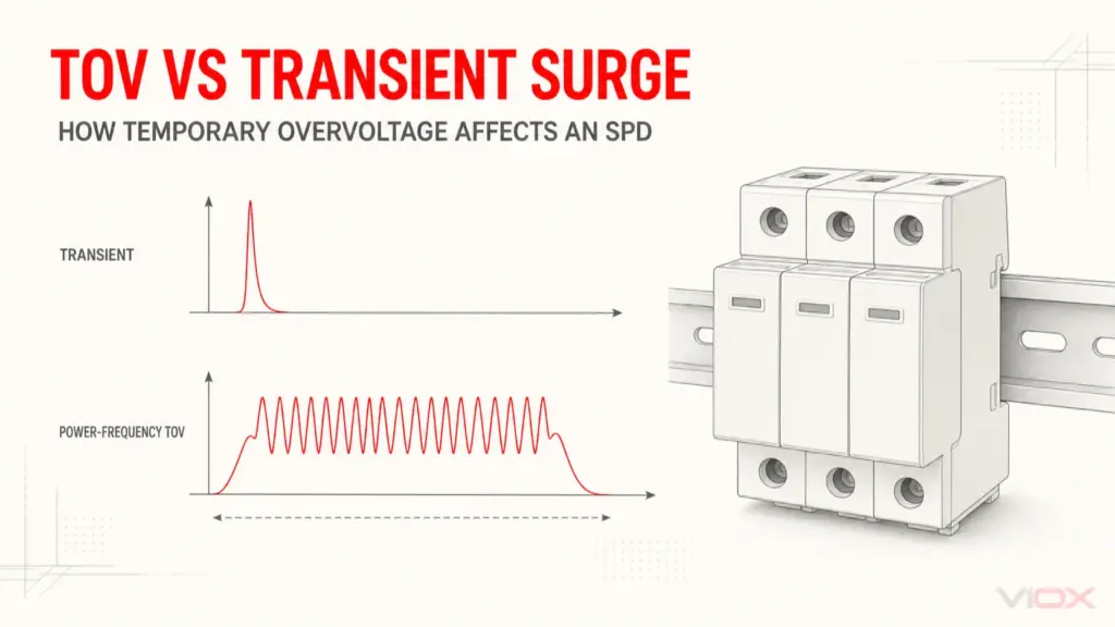
A surge protective device limits a short-duration overvoltage and diverts surge current through its designed protection path. On the PV DC side, it is intended to reduce the transient voltage reaching the inverter, combiner equipment, monitoring hardware, or other connected devices.
An SPD does not replace a DC fuse, breaker, isolator, bonding system, or external lightning-protection system. It also does not regulate a sustained high voltage. These functions must be coordinated as part of the installation.
PV systems commonly require separate reviews at four interfaces:
- the array or combiner-box DC circuits;
- the inverter DC input;
- the inverter AC output or distribution board; and
- data, sensor, or communications lines.
The DC and AC products are not interchangeable. IEC 61643-31:2018 applies to SPDs dedicated to the DC side of photovoltaic generators and inverters up to 1,500 V DC. IEC 61643-32:2017 addresses selection and application for PV installations. AC-side devices follow the applicable AC SPD product and installation framework.
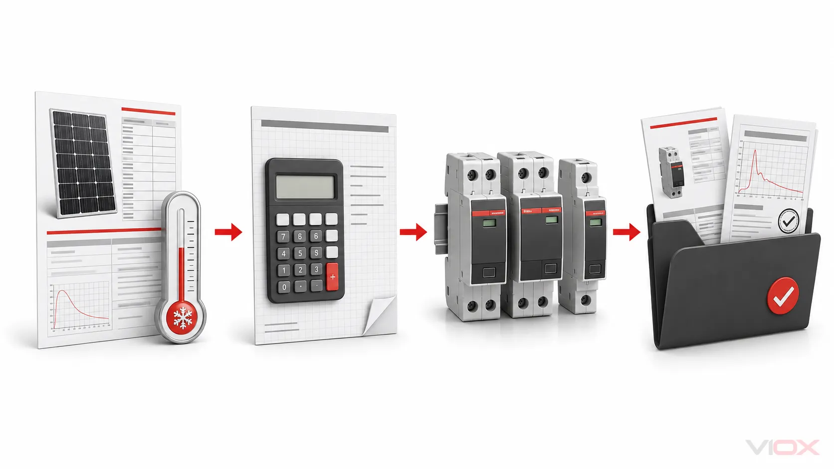
Step 1: Calculate Maximum Cold-Weather String Voc
PV module open-circuit voltage rises as cell temperature falls. That makes the array’s maximum possible string Voc—not the inverter’s nominal DC voltage—the starting point for Ucpv selection.
Use the module manufacturer’s voltage-temperature coefficient and the design minimum temperature required by the project method. A simplified calculation is:
Voc,max = Nseries × Voc,module,STC × [1 + |βVoc| × (25 − Tmin)]Where:
Nseriesis the number of modules in series in one string;Voc,module,STCis module open-circuit voltage at standard test conditions;βVocis the absolute value of the Voc temperature coefficient per degree Celsius, expressed as a decimal; andTminis the design temperature used by the applicable project method.
Worked example
Assume 20 modules in series, each with Voc of 45 V at STC. The module datasheet gives a Voc temperature coefficient of −0.30%/°C, and the design minimum temperature is −10°C.
String Voc at STC = 20 × 45 V = 900 V
Temperature difference = 25 − (−10) = 35°C
Cold correction factor = 1 + 0.003 × 35 = 1.105
Voc,max = 900 V × 1.105 = 994.5 V
The result is too close to treat a 1,000 V Ucpv label as an automatic choice. The engineer must apply the relevant standard method, required margin, module tolerance, inverter maximum input voltage, and the SPD manufacturer’s instructions. Some IEC-oriented manufacturer guidance applies an additional Ucpv relationship to maximum array voltage; use the project-approved method rather than mixing rules from different markets.
Do not increase Ucpv without considering protection level. A higher continuous operating voltage may also be associated with a higher Up. Selection is a coordination problem: the SPD must tolerate normal maximum PV voltage and still limit transients below the withstand objective of the protected equipment, including installation lead effects.
Step 2: Match the SPD to the PV DC System
The label “DC SPD” is not enough. Confirm that the device is intended for photovoltaic DC duty and matches the circuit configuration.
| Check | Why it matters | Evidence to request |
|---|---|---|
| PV DC application | DC arc and disconnection behavior differ from AC | Datasheet naming PV DC use and applicable product standard |
| Ucpv | Must remain suitable at maximum normal PV voltage | Rated value and manufacturer selection rule |
| Protection modes and poles | Must match grounded, functionally earthed, or floating PV architecture | Manufacturer circuit diagram for the exact model |
| Iscpv or stated short-circuit behavior | The SPD must be safe at the available PV fault-current conditions | Test/rating data and permitted protective arrangement |
| Pluggable cartridge coding | Prevents fitting an incompatible replacement | Base and cartridge part-number compatibility |
| Environmental limits | Combiner boxes can experience heat, moisture, condensation, and altitude effects | Temperature, altitude, enclosure, and pollution-degree limits |
IEC 61643-31 explicitly excludes SPDs for PV systems with energy storage such as batteries. That does not mean a PV-plus-storage project cannot use surge protection; it means the battery-side and converter-side protection require their own equipment and evidence. Use the BESS surge-protection guide for that separate application.
Step 3: Choose Type 2 or Type 1+2 from Exposure
Type is not a quality grade. Type 1 and combined Type 1+2 devices are evaluated for lightning-current duty; Type 2 devices address the surge-current test context used for induced and switching surges. The selection follows the installation’s lightning current paths, not the assumption that the larger label is always better.
| Installation condition | Starting point for design review | What must decide the final choice |
|---|---|---|
| Rooftop PV without an external LPS | Type 2 is commonly evaluated for induced surges | Local rules, risk assessment, inverter instructions, cable routing, and site exposure |
| Building with an external LPS and adequate separation maintained | Type 2 may be part of the coordinated design | LPS design, separation calculation, bonding concept, and applicable standard |
| External LPS present and separation cannot be maintained | Type 1 or Type 1+2 duty is commonly evaluated at relevant entry points | Expected lightning-current sharing, LPS class, conductor routing, and project specification |
| Exposed ground-mount or utility PV site | Project-specific Type 1/Type 1+2 and Type 2 coordination may be justified | Lightning risk, meshed earthing, multiple cable entries, downtime cost, and engineering study |
| Replacement in an existing combiner | Match the approved design; do not infer Type from appearance | Original drawings, exact base/cartridge data, and site change history |
Iimp belongs to the Type 1 lightning-current test context, typically associated with a 10/350 μs impulse. In and Imax are associated with the 8/20 μs current-wave context used for Type 2 performance. These values are not interchangeable, so a higher peak kA number under one waveform does not prove superior capability under another. The Type 1, Type 2, and Type 3 guide explains the classification boundary.
Step 4: Decide Where the Solar DC SPD Is Needed
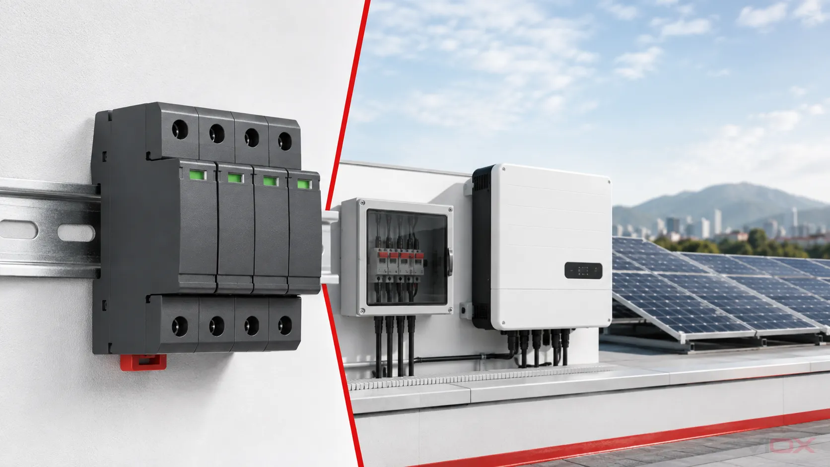
Placement controls the real protection path. The SPD should be evaluated near the cable entry or equipment it protects, with connections kept as short and direct as the approved design permits.
| Location | Purpose | Design questions |
|---|---|---|
| Array junction or string combiner | Limit surges entering or induced on outdoor string circuits | Is the enclosure suitable? Is the bonding point close? Does each input architecture match the SPD? |
| Inverter DC input | Reduce transient voltage at the inverter terminals | Is protection integrated and documented? What is the distance from the array-side SPD? |
| Both ends of a longer DC cable route | Control transient voltage at both cable endpoints | Does IEC 61643-32, the inverter manual, or the project design call for added protection based on distance? |
| Inverter AC output or AC board | Address surges entering through the AC network | Use an AC SPD suitable for the supply system; do not reuse a PV DC device by assumption |
| Monitoring and communications interface | Protect signal paths that can bypass power SPDs | Match signal voltage, interface, bandwidth, and grounding concept |
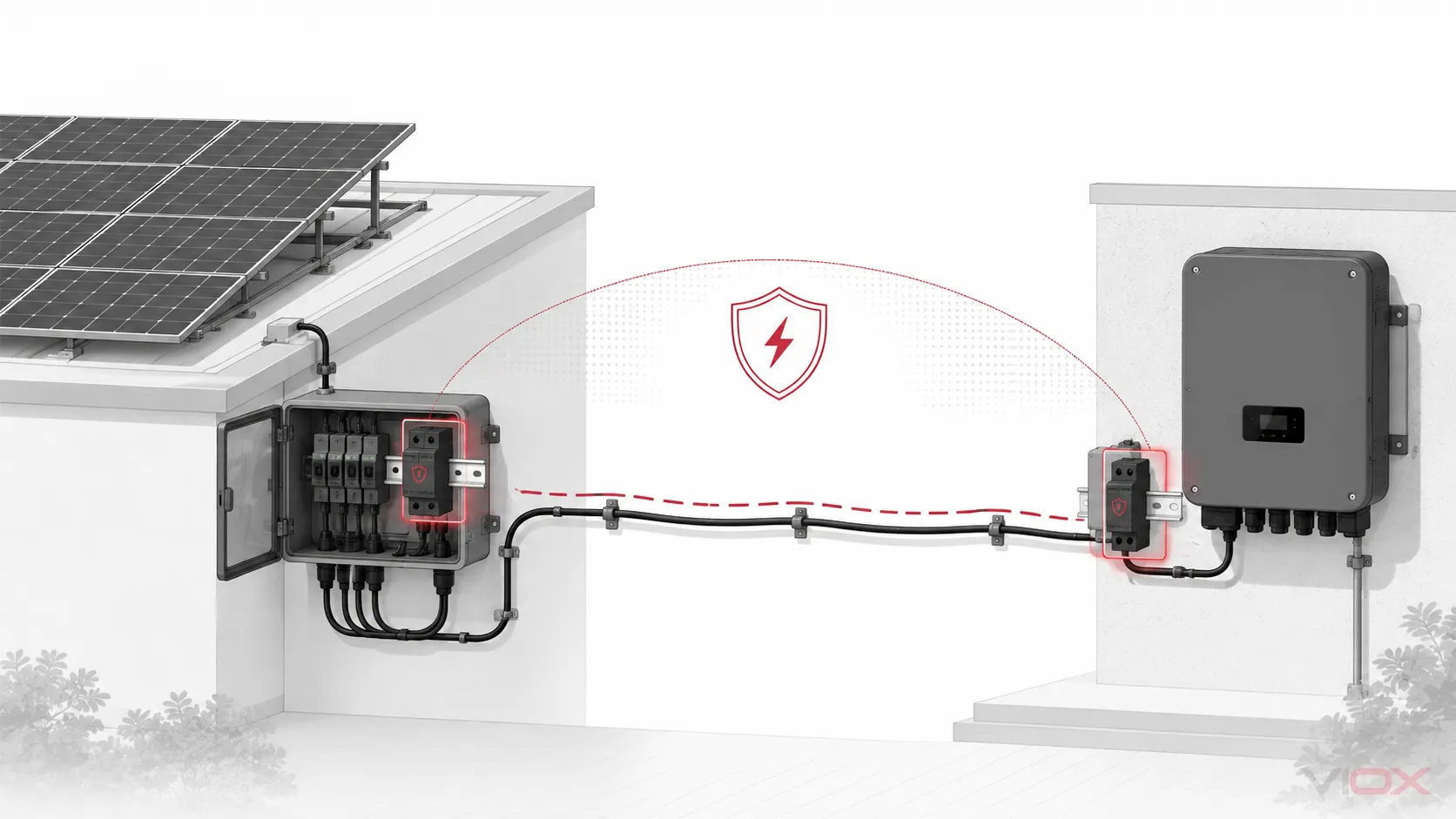
Many guides cite about 10 m between equipment and an SPD as a checkpoint for evaluating additional protection. Treat that as an application-design trigger, not a universal code sentence. The applicable edition, system topology, cable route, LPS design, equipment withstand, and manufacturer guidance determine the final arrangement.
Likewise, short leads matter because the fast change of surge current creates inductive voltage rise in the connection conductors. The installed protective voltage is not just the marked Up; conductor length and routing add to what the equipment can experience. Avoid large loops and remote mounting, but take conductor size and routing from the exact installation instructions.
Step 5: Read the Ratings as a Set
| Marking or parameter | Selection question | Common error |
|---|---|---|
| Ucpv | Is it suitable for maximum cold-weather string voltage and the PV architecture? | Selecting from nominal inverter voltage |
| Up | Does the protective level coordinate with equipment withstand after connection effects? | Assuming the lowest catalog Up wins in every system |
| In | Is the repeated nominal discharge-current capability appropriate to the Type 2 duty? | Calling In the maximum possible lightning current |
| Imax | What maximum Type 2 discharge-current test value is declared? | Comparing it directly with Iimp |
| Iimp | What Type 1 lightning-current capability is declared per pole or protection mode? | Adding unlike values or ignoring the waveform |
| Iscpv/SCCR direction | Can the SPD and protection arrangement withstand the available short-circuit condition? | Choosing a backup breaker from habit |
| Uoc or system configuration limits | Which PV architecture and voltage relationships are permitted? | Assuming every two-pole-looking product fits every floating array |
| Status and remote contact | How will loss of protection be detected? | Treating a closed combiner-box indicator as a maintenance program |
Use the SPD datasheet guide when comparing declarations. Do not rank devices by Imax alone; voltage suitability, protection level, Type, short-circuit safety, and installation geometry all affect the outcome.
Step 6: Verify Short-Circuit and Backup Protection
An SPD is connected in parallel with the circuit it protects. It carries little normal current in a healthy steady state, but a failed or degraded protection component can create a fault condition. The external fuse or breaker, internal protection, and stated short-circuit rating must therefore be coordinated with the available current and installation instructions.
Before approval, record:
- available short-circuit current at the installation point;
- the SPD’s applicable short-circuit or PV fault-current declaration;
- whether external backup protection is required;
- permitted device type and maximum/minimum ratings, where the manufacturer specifies them;
- conductor cross-section and terminal torque;
- isolation method for safe maintenance; and
- whether replacing one cartridge restores all protection modes.
Never substitute a larger fuse or breaker because the previous device operated or because nuisance operation is suspected. The existing-breaker connection guide explains the evidence required before sharing or selecting an upstream device.
Solar DC SPD Selection by Project Type
| Project | Practical shortlist | Extra questions |
|---|---|---|
| Small residential rooftop | PV Type 2 near the inverter or approved array entry point | Is an SPD already integrated? What AC-side protection exists? Is external LPS present? |
| Commercial rooftop with combiners | Type 2 at documented DC entry points; Type 1+2 where LPS/exposure requires | Cable distances, rooftop zones, remote indication, enclosure temperature, and spare cartridges |
| Ground-mounted plant | Engineered multi-location coordination | Meshed earth network, long runs, multiple inverter stations, lightning density, and maintenance monitoring |
| 1,500 V utility array | PV DC SPD specifically documented for the voltage class | Maximum string Voc, altitude/temperature derating, inverter limits, and exact test evidence |
| PV plus battery storage | Separate PV, battery, converter, AC, and signal reviews | IEC 61643-31’s PV scope does not automatically cover the battery-side application |
Documents to Request Before Purchase
A useful RFQ states the system before it asks for a part number.
| RFQ field | Project input |
|---|---|
| Application | Rooftop, ground-mount, combiner, inverter DC input, or replacement |
| Maximum string Voc | Corrected value and calculation method |
| Nominal and maximum system voltage | Include inverter and array limits |
| External LPS | Present/absent, class, and separation status |
| SPD Type | Type 2 or Type 1+2 based on the design |
| Required protection modes | From the PV topology and manufacturer diagram |
| Up, In, Imax, Iimp | Required values in the correct test context |
| Available fault current | At the intended installation point |
| Backup protection | Required type/rating or evidence that none is needed |
| Environment | Enclosure, temperature, altitude, humidity, condensation, and pollution conditions |
| Monitoring | Visual status, remote contact, and maintenance response |
| Evidence | Datasheet, declaration/certificate, test report availability, installation manual, and replacement compatibility |
For a combiner-box bill of materials and protection-function boundary, use the solar combiner-box protection design guide. To check a delivered DC SPD before installation, use the bounded DC SPD pre-installation inspection and test guide.
Common Selection Errors
- Using an AC SPD on the PV DC side. Similar enclosure shape does not establish PV DC suitability.
- Using nominal voltage instead of cold-weather Voc. This can place normal operation too close to or above Ucpv.
- Choosing by kA alone. The waveform, Type, protection mode, and voltage level matter.
- Assuming Type 1+2 is always better. It must still coordinate with the equipment and installation.
- Protecting only one interface. DC, AC, and communications paths need separate review.
- Copying a generic connection diagram. Pole arrangement and protection modes are system- and model-specific.
- Ignoring short-circuit safety. Backup protection and available fault current are not optional documentation fields.
- Leaving status unseen. A failed cartridge inside a closed outdoor box can remain unnoticed without inspection or remote signaling.
Frequently Asked Questions
What size SPD do I need for a solar system?
There is no single kA “size.” Calculate maximum cold-weather string Voc, select suitable Ucpv and system configuration, choose the SPD Type from exposure, then coordinate Up, discharge-current ratings, fault-current safety, and placement.
Is a 1,000 V DC SPD suitable for every 1,000 V solar system?
No. “1,000 V system” is not the calculation result. The longest string’s cold-weather Voc, the SPD’s Ucpv rule, the inverter limit, topology, and project margin all need verification.
Do I need an SPD at both the combiner and inverter?
Possibly. Longer cable routes, separate structures, cable-entry exposure, equipment withstand, and the governing design may justify protection at both endpoints. Do not turn a distance rule of thumb into a universal prescription.
Can one SPD protect both the DC and AC sides of a solar inverter?
No as a general selection assumption. PV DC and AC circuits have different voltage behavior, product requirements, protection modes, and connection arrangements. Evaluate each interface separately.
Does a solar SPD protect against a direct lightning strike?
An SPD is one part of a coordinated lightning and surge protection concept. Direct-lightning exposure can require an external LPS, bonding, separation, Type 1 lightning-current-capable SPDs, and risk-based design. No single SPD guarantees protection from every strike or energy level.
Technical References
- IEC 61643-31:2018 — Requirements and test methods for PV DC SPDs
- IEC 61643-32:2017 — Selection and application principles for PV SPDs
- DEHN 2025 technical catalogue — SPD terms and PV Ucpv guidance
- NEMA Surge Protection Institute — How SPDs work
After the project inputs are documented, compare VIOX surge protective device options against the exact PV DC voltage, Type, protection modes, fault-current requirements, environment, and evidence package.
This guide supports selection and procurement review; it is not a project wiring instruction. Final design, installation, testing, and maintenance must follow the applicable rules, inverter documentation, exact SPD instructions, and qualified electrical review.