On this page
A contactor is an electrically operated switch used to control motors, heaters, lighting systems, capacitor banks, and other power loads. In a typical normally open contactor, a control signal energizes the coil and closes the main contacts; removing the signal allows them to reopen. This lets a low-power control circuit switch a higher-power load remotely and repeatedly.
Most industrial contactors discussed in this guide are electromechanical magnetic contactors. In everyday industrial usage, “magnetic contactor” is therefore often shortened to “contactor.” Unlike a circuit breaker, however, a contactor is a control device—not a short-circuit or overload protective device.
| Question | Short answer |
|---|---|
| What does a contactor do? | Switches a power circuit on or off in response to a control signal |
| What commonly controls it? | Push buttons, thermostats, timers, sensors, relays, or programmable logic controllers (PLCs) |
| What loads does it control? | Motors, HVAC equipment, heaters, lighting, pumps, compressors, and industrial machinery |
| Does it protect against overloads or short circuits? | No; protection must be provided by coordinated breakers, fuses, and/or overload relays |
| What standard commonly covers industrial electromechanical contactors? | IEC 60947-4-1; North American products may also be evaluated to UL 60947-4-1 |
How Does a Contactor Work?
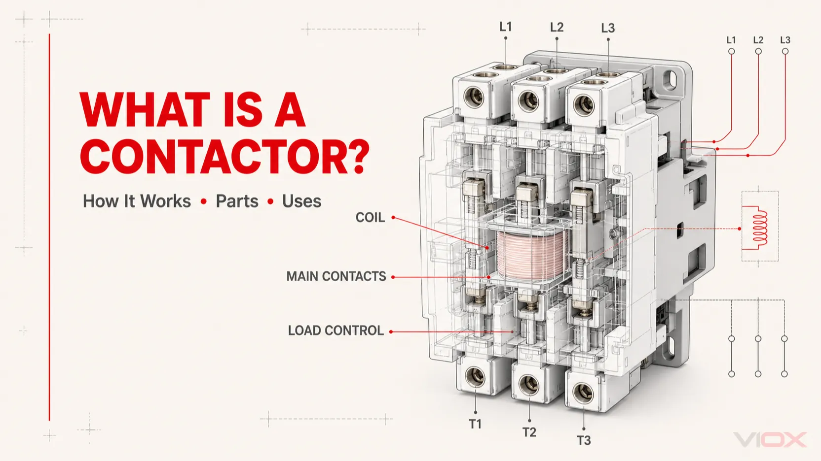
A magnetic contactor converts electrical energy in its coil into mechanical movement. Its operating sequence is simple:
- The control circuit energizes the coil. Voltage is applied across coil terminals A1 and A2.
- The coil creates a magnetic field. The field attracts the movable armature toward the fixed magnetic core.
- The main contacts change state. Normally open main contacts close and supply power to the load. Auxiliary contacts change state at the same time for interlocking, status indication, or control logic.
- The coil is de-energized. When the control signal is removed, the magnetic field collapses.
- The return spring opens the contactor. The armature returns to its normal position and the main contacts disconnect the load.
In a typical three-phase motor circuit, incoming power connects to L1, L2, and L3, while the motor side connects to T1, T2, and T3. The exact terminal markings and arrangement must always be confirmed against the device diagram or datasheet.
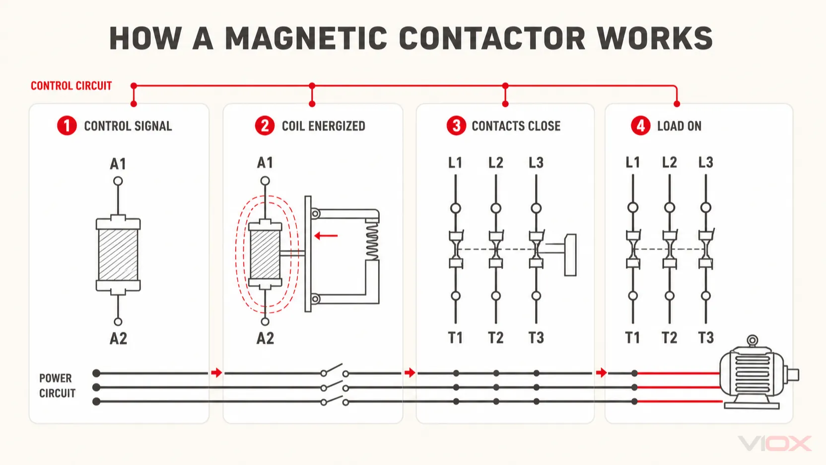
A contactor separates the low-power control command from the power circuit feeding the load.
What Happens When the Contacts Open?
Opening a circuit under load can create an electrical arc. Contactors use contact geometry and arc-control structures to manage the switching arc within their rated duty.
Alternating-current (AC) arcs benefit from natural current zero crossings. Direct-current (DC) arcs do not, so a DC contactor may require a different contact arrangement, magnetic arc control, polarity-sensitive connections, or other manufacturer-specific arc-extinction features. An AC contactor should not be assumed suitable for a DC load—or vice versa—based only on its current rating. See the detailed comparison of AC and DC contactors.
Main Parts of a Contactor
The exact design varies by product family, but most electromechanical contactors contain the following functional parts.
| Part | Function | Common identification |
|---|---|---|
| Electromagnetic coil | Produces the magnetic field that operates the mechanism | A1 and A2 |
| Fixed core and movable armature | Convert magnetic force into mechanical movement | Inside the contactor body |
| Main power contacts | Make and break the load current | L1/L2/L3 and T1/T2/T3 on many three-pole devices |
| Auxiliary contacts | Provide holding, interlocking, signaling, or PLC feedback | 13–14 for a typical NO contact; 21–22 for a typical NC contact |
| Return spring | Returns the mechanism to its normal state when the coil is de-energized | Internal |
| Arc-control system | Helps cool, divide, stretch, or extinguish the switching arc | Near the main contacts |
| Terminals and enclosure | Provide electrical connections, insulation, and mechanical support | Product-specific |
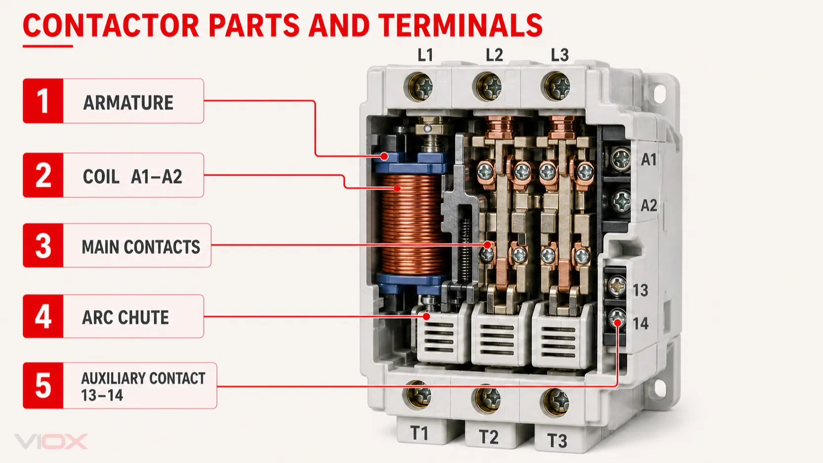
The coil and armature operate the main contacts; auxiliary contacts report or control the contactor’s state.
Terminal numbers are useful clues, but they are not a substitute for the manufacturer’s diagram. Auxiliary-contact arrangements, coil type, built-in suppressors, and terminal locations vary. For a deeper component-level explanation, see inside an AC contactor.
What Is a Contactor Used For?
Contactors are used when a load must be controlled remotely, automatically, or frequently.
Motor Control
In a direct-on-line motor starter, the contactor starts and stops the motor. A circuit breaker or fuse provides short-circuit protection, while an overload relay monitors sustained motor overcurrent and opens the contactor’s control circuit when required.
This separation of functions is fundamental:
- Breaker or fuse: short-circuit protection
- Overload relay: motor overload protection
- Contactor: normal start-and-stop switching
HVAC and Pump Systems
Thermostats, pressure switches, float switches, and building controllers can energize contactor coils to operate compressors, fans, pumps, or electric heating stages. The contactor keeps load current out of the low-power control device.
Lighting and Heating
Contactors can switch groups of luminaires or resistance-heating loads from timers, occupancy controls, or energy-management systems. The load type and inrush behavior still matter: a device suitable for a resistive heater is not automatically suitable for a motor or high-inrush lighting load at the same current.
Industrial Automation
PLCs and control relays use contactors to switch conveyors, machine tools, ventilation equipment, and other loads. Auxiliary contacts provide electrical interlocking and status feedback, although an auxiliary contact indicates the mechanism’s commanded state and is not always proof that every main pole is electrically healthy.
Contactor vs Relay vs Circuit Breaker vs Motor Starter
These devices may appear in the same panel, but they perform different jobs.
| Device | Primary job | Typical role in a motor circuit | Provides overcurrent protection? |
|---|---|---|---|
| Contactor | Frequent remote switching of a load | Connects and disconnects motor power | No |
| Control relay | Switches signals or lower-power control circuits | Logic, isolation, interlocking, or interface duty | No |
| Circuit breaker | Detects and interrupts overcurrent | Protects the feeder or branch circuit against faults | Yes, according to its trip functions and ratings |
| Motor overload relay | Detects sustained motor overload or phase-related abnormalities, depending on type | Commands the contactor to open | Overload protection, but not normally short-circuit interruption |
| Motor starter | Combines switching and motor overload functions; may be part of a coordinated assembly | Starts, stops, and protects the motor according to the assembly design | Depends on the included components |
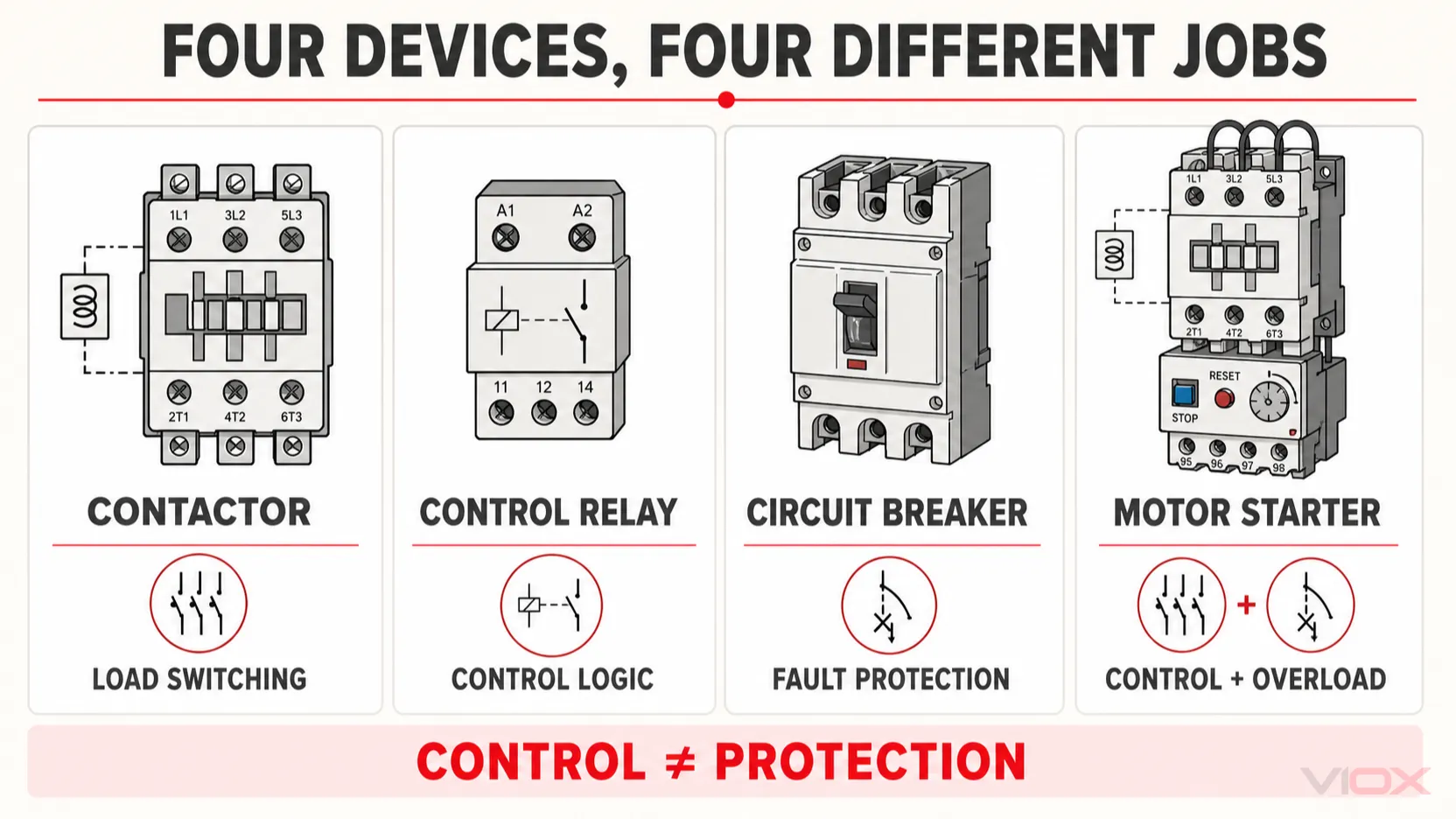
A contactor and a circuit breaker are therefore complementary, not interchangeable. The fuller engineering distinction is covered in contactor vs circuit breaker, while low-power switching differences are explained in contactor vs relay.
Common Types of Contactors
AC and DC Contactors
The load circuit and coil circuit must each be checked independently. A contactor may have an AC-rated power circuit with an AC or DC control coil, depending on its design. DC load interruption usually requires contact structures specifically rated for DC voltage, current, polarity, and time constant.
IEC and NEMA Contactors
IEC and NEMA are different rating and selection frameworks, not simple quality grades.
- IEC contactors are selected closely around application data such as operational current, utilization category, operating voltage, and expected switching duty.
- NEMA contactors use standardized controller sizes and horsepower-based application tables for common North American motor duties. They are often physically larger than IEC products selected for a comparable application.
IEC contactors are not generally assigned a universal A/B/C size sequence. Always use the manufacturer’s rating tables rather than trying to convert enclosure dimensions or frame letters into switching capability.
Modular Contactors
Modular contactors are DIN-rail devices commonly used in building installations for lighting, heating, ventilation, and similar loads. They are not automatically interchangeable with industrial motor contactors. Compare their application standard, utilization category, switching frequency, coil duty, and load characteristics. See modular contactor vs traditional AC contactor.
Application-Specific Contactors
Some applications require contactors designed and rated for a particular switching challenge, including capacitor banks, reversing motor circuits, lighting loads, safety-related control systems, and medium-voltage vacuum switching. A general-purpose current rating alone is not enough to approve a device for these duties.
How to Select a Contactor
Start with the application, not with the largest ampere value printed on the front label.
| Selection input | What to verify |
|---|---|
| Load type | Motor, resistance heating, lighting, capacitor bank, transformer, or another load |
| Utilization category | The category that represents the actual making and breaking duty |
| Operational voltage and current | Manufacturer rating at the required voltage and utilization category |
| Motor data | Rated power/current, starting method, starting frequency, and jogging or reversing duty |
| Coil supply | AC or DC, nominal voltage, frequency where applicable, and allowable operating range |
| Number of poles | Conductors that must be switched; follow system and equipment requirements |
| Auxiliary contacts | Quantity and NO/NC arrangement required for holding, interlocking, or feedback |
| Operating duty | Switching frequency and required electrical endurance for the actual load |
| Coordination | Upstream short-circuit protective device and overload protection specified for the assembly |
| Installation conditions | Ambient temperature, altitude, enclosure, ventilation, pollution, and mounting requirements from the manufacturer |
Manufacturer selection guidance likewise requires the main poles, auxiliary contacts, coil supply, utilization category, operating duty, and installation conditions to be evaluated for the specific application.
Under IEC practice, utilization categories describe the intended switching duty. Common examples include:
| Category | Typical duty |
|---|---|
| AC-1 | Non-inductive or slightly inductive AC loads, such as resistance heating |
| AC-3 | Starting squirrel-cage motors and opening the circuit while the motor is running |
| AC-4 | Starting, plugging, inching, or reversing squirrel-cage motors |
AC-4 is more severe than AC-3 because the contactor may make and break high motor current. The same contactor can therefore have different operational-current ratings under different categories. Read the full guide to AC-1, AC-3, and AC-4 utilization categories before selecting by current alone.
Standards and Protection Boundaries
IEC 60947-4-1 covers electromechanical contactors and motor starters intended for applicable low-voltage distribution, motor, and other load circuits. In North America, relevant industrial control products may be evaluated under standards such as UL 60947-4-1, subject to the product and assembly application.
These standards do not mean that every contactor can safely interrupt a prospective short circuit. A contactor must be applied with the short-circuit protective device, overload device, conductors, and enclosure required by the manufacturer, applicable standard, and local electrical rules. Product certification must be verified for the exact model—not inferred from the product category.
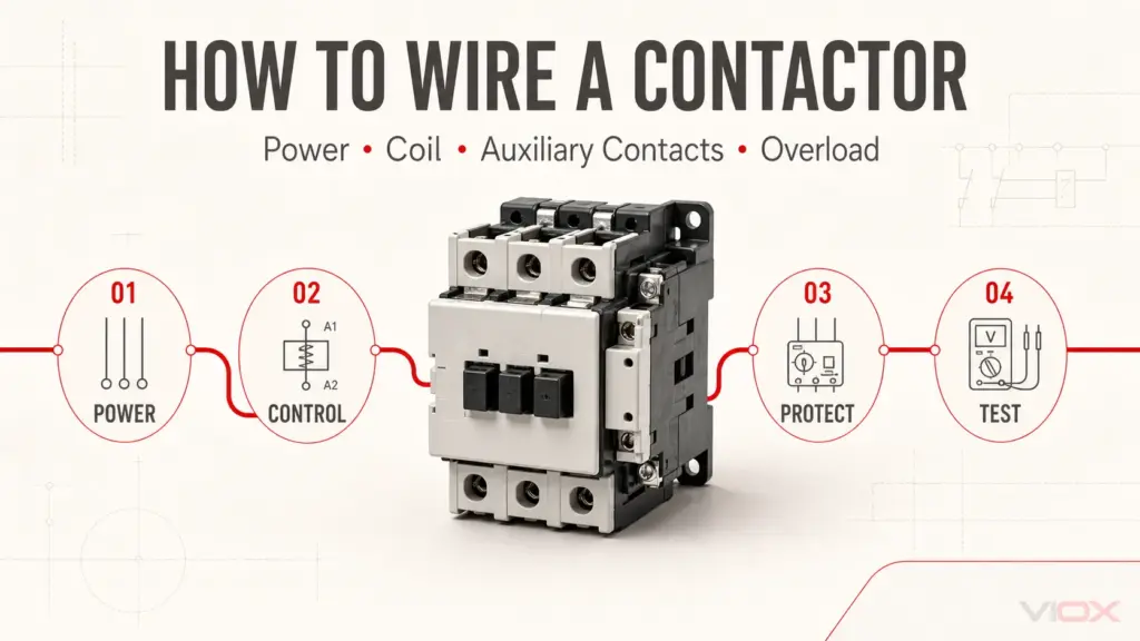
Basic Contactor Wiring Concept
A contactor circuit normally has two distinct paths:
- Power circuit: supply → short-circuit protective device → contactor main contacts → overload relay where required → load
- Control circuit: control supply → stop/safety/overload contacts → start command or controller → contactor coil
Coil terminals A1 and A2 must receive the voltage shown on the coil or datasheet. They do not automatically match the power-circuit voltage. Incorrect coil voltage can prevent pull-in, cause chatter, overheat the coil, or damage the device.
Installation, testing, and maintenance must be performed by qualified personnel under applicable electrical safety procedures.
Frequently Asked Questions
Is a magnetic contactor the same as a contactor?
A magnetic contactor is an electromechanical contactor operated by an electromagnetic coil. Because this is the most common design, “magnetic contactor” and “contactor” are often used interchangeably. Other switching technologies and manually operated devices also exist, so the product description should still be checked.
What is the difference between a contactor and a relay?
Both can use an electromagnetic coil, but a contactor is designed for power-load switching and includes features suited to the resulting contact and arc duty. A control relay is generally used for signaling, isolation, and logic circuits. Selection must be based on the manufacturer’s load ratings, not the device name alone.
Does a contactor protect a motor?
Not by itself. The contactor switches the motor. A coordinated fuse or circuit breaker provides short-circuit protection, and an overload relay or other motor-protection device provides the required overload functions.
Why does a contactor have A1 and A2 terminals?
A1 and A2 identify the two coil connections on many contactors. Applying the specified coil voltage across them operates the contactor. Coil voltage, AC/DC type, polarity requirements, and integrated suppression must be verified from the exact product documentation.
What do 13–14 and 21–22 mean on a contactor?
Under common IEC terminal identification, 13–14 denotes a normally open auxiliary contact and 21–22 denotes a normally closed auxiliary contact. Not every device includes both, and the wiring diagram remains authoritative.
Can I use an AC contactor for DC?
Only when the manufacturer explicitly provides a suitable DC load rating for the required voltage, current, polarity, and circuit conditions. DC arcs are more difficult to interrupt because there is no natural current zero crossing, so an AC load rating cannot be transferred directly to DC service.
How can I tell whether a contactor is faulty?
Symptoms can include failure to pull in, chatter, abnormal noise, overheating, damaged terminals, or contacts that do not open or close correctly. Isolate the circuit and follow an appropriate diagnostic procedure. See the contactor testing guide and contactor troubleshooting guide for separate step-by-step workflows.
Conclusion
A contactor is the power-switching element that allows a relatively low-power control signal to operate a higher-power load. Its coil moves the main and auxiliary contacts; the selected utilization category defines the kind of switching duty it can perform.
The central design rule is equally important: a contactor controls the load, while coordinated breakers, fuses, and overload devices provide protection. Select the contactor from the actual load, utilization category, coil supply, operating duty, and manufacturer coordination data—not from current rating alone.
For product evaluation, compare application-specific ratings and documentation in the VIOX AC contactor range.