On this page
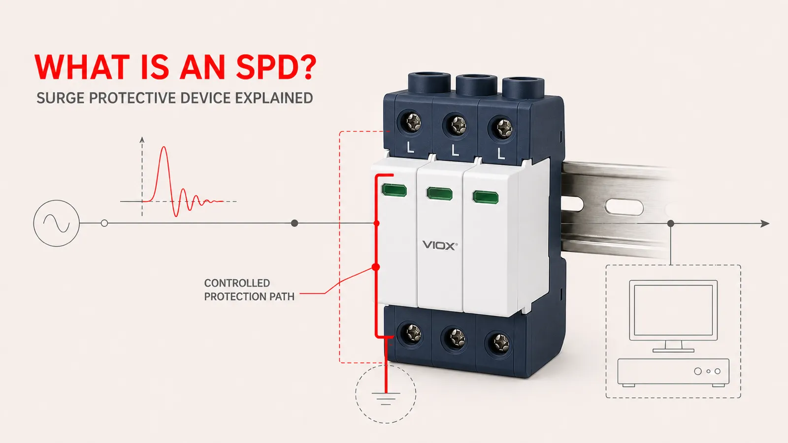
A surge protective device (SPD) limits transient overvoltage by diverting surge current through a controlled protection path. Most low-voltage power SPDs remain in a high-impedance standby state during normal operation and become conductive during a surge, reducing the voltage stress reaching downstream equipment.
An SPD does not make a surge disappear, and it does not replace a circuit breaker, correct earthing and bonding, or an external lightning-protection system. It is one coordinated layer in an electrical protection system.
If you are evaluating products rather than learning the operating principle, review the VIOX surge protective device range for AC, DC, and photovoltaic applications.
What Does SPD Stand For in Electrical Systems?
SPD stands for Surge Protective Device. This is the term used in electrical standards, technical specifications, panel schedules, and product datasheets. “Surge protector” is a broader everyday expression, while SPD is the more precise engineering term for a device designed to limit transient overvoltage and conduct surge current.
The word transient is important. An SPD responds to short-duration voltage disturbances. It is not designed to regulate a supply that remains continuously too high or too low.
For readers who only need the acronym and terminology, see SPD Full Form in Electrical.
What Does an SPD Do—and What Does It Not Do?
The easiest way to understand an SPD is to separate its function from adjacent protection functions.
| Protection function | What it addresses | What it does not replace |
|---|---|---|
| Surge protective device | Short-duration transient overvoltage and associated surge current | Circuit breaker, earthing, bonding, voltage regulation, or complete lightning protection |
| Circuit breaker or fuse | Sustained overcurrent and short-circuit faults | Transient voltage limitation |
| Earthing and bonding system | Reference potential, fault-current path, and equipotential bonding | A device that limits transient voltage at equipment terminals |
| Voltage regulator or automatic voltage protector | Longer-duration overvoltage, undervoltage, or voltage variation, depending on the device | Fast surge-current diversion |
| External lightning-protection system | Interception and conduction of direct lightning current outside or through the structure | Internal coordination of surges entering power and signal circuits |
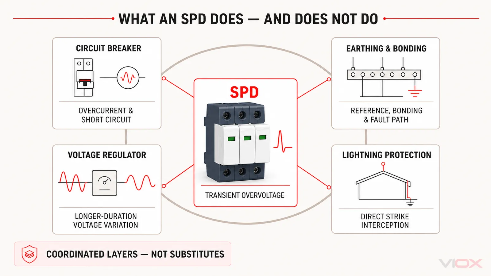
An SPD can support lightning protection by limiting conducted and induced surges, but an SPD by itself is not a complete lightning-protection system. Likewise, a breaker may provide required backup protection for an SPD, but the two devices perform different jobs.
How Does an SPD Work?
Most low-voltage power SPDs are connected in parallel with the circuit they protect. Under normal voltage, the surge-limiting elements remain non-conductive or present a very high impedance. When the voltage rises rapidly above the device’s operating threshold, those elements change state and provide a lower-impedance path for surge current.
The operating sequence can be simplified into five stages:
- Normal operation: System voltage remains within the SPD’s continuous operating range, so the protection path stays in standby.
- Transient begins: Lightning influence, switching, fault clearing, or another disturbance produces a rapid voltage rise.
- SPD changes impedance: A voltage-limiting or voltage-switching component becomes conductive.
- Surge current follows the protection path: Current is diverted between the conductors defined by the SPD configuration, reducing the voltage stress across downstream equipment.
- SPD recovers or disconnects: After the event, a serviceable SPD returns to standby. If a protective element has reached an unsafe condition, an internal disconnector may isolate it and change the status indication.
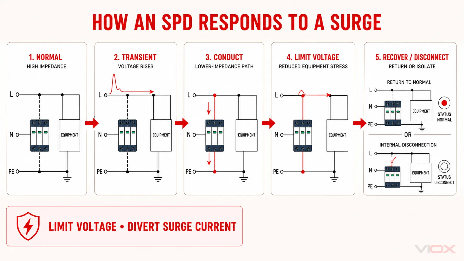
This response is often described as clamping, but not every SPD uses the same internal technology or response mode.
Common Surge-Limiting Technologies
| Technology | Typical behavior | Common use | Important boundary |
|---|---|---|---|
| Metal oxide varistor (MOV) | Becomes increasingly conductive as voltage rises | AC and DC power SPDs | Accumulated surge stress can degrade the element, so thermal disconnection and status indication matter |
| Gas discharge tube (GDT) | Switches into a conductive discharge state after sparkover | Power, telecom, and signal protection | Follow-current behavior and coordination depend on the design |
| Transient voltage suppressor (TVS) diode | Provides fast avalanche clamping | Sensitive electronics and low-voltage signal circuits | Generally addresses lower-energy circuits than main power SPDs |
The correct component combination depends on the system, protection mode, energy duty, residual-voltage requirement, and applicable product standard. Component technology alone is not a complete selection method.
Where Does the Surge Current Go?
It is common to say that an SPD “sends the surge to ground,” but that description is incomplete. An SPD limits voltage between the conductors connected to its protection modes. Depending on the electrical system and SPD topology, those modes may include:
- line to neutral (L–N)
- line to protective earth (L–PE)
- neutral to protective earth (N–PE)
- line to line (L–L)
- DC positive to DC negative (DC+–DC−)
- a DC conductor to protective earth
The surge current follows the available protection and bonding path. That is why the earthing arrangement, protection mode, conductor routing, and SPD topology all affect real performance. A technically strong SPD can still provide poor protection if its connection path adds excessive impedance during a fast surge.
What Causes Transient Overvoltage?
A transient overvoltage is a rapid, short-duration voltage rise above the normal operating level. It may enter through a power circuit, a photovoltaic string, a communication cable, a sensor line, or another conductive path.
| Source | Typical mechanism | Systems commonly exposed |
|---|---|---|
| Lightning influence | Direct coupling, induced voltage, or conducted surge current | Utility supplies, outdoor feeders, PV arrays, telecom and signal lines |
| Utility and distribution switching | Transformer switching, capacitor-bank switching, fault clearing, or network reconfiguration | Main distribution and downstream panels |
| Inductive load switching | Rapid interruption of current in motors, contactor coils, solenoids, or other inductive loads | Industrial control panels and automation systems |
| Power-electronic switching | Fast switching edges and interactions among converters, drives, inverters, UPS systems, and chargers | Industrial systems, renewable energy, EV charging, and data infrastructure |
These sources do not create identical waveforms or energy levels. SPD selection therefore depends on where the device is installed and which surge environment it is expected to address.
Type 1, Type 2, and Type 3 SPD: A Short Orientation
SPD types describe tested protection roles under an applicable standard. They should not be treated as simple quality grades.
| SPD type | General protection role | Common installation context | Ratings commonly reviewed |
|---|---|---|---|
| Type 1 | Handles lightning-current duty where partial lightning current may be expected | Service entrance or lightning-protection boundary | Iimp and the associated test waveform, plus voltage and short-circuit coordination |
| Type 2 | Provides distribution-level protection against residual lightning effects and switching surges | Main or sub-distribution boards and control panels | In, Imax, Up, Uc/MCOV, and coordination requirements |
| Type 3 | Provides downstream or equipment-level fine protection | Close to sensitive equipment, coordinated with upstream SPDs | Combination-wave performance, protection level, and installation conditions |
| Type 1+2 | Combines tested Type 1 and Type 2 duties in one product | Main distribution points requiring both functions | Iimp together with the relevant Type 2 ratings |
IEC and UL type designations must be read within their own standards and product markings; they are not a universal one-to-one conversion table. For a detailed location, waveform, and coordination comparison, see Type 1 vs Type 2 vs Type 3 SPD.
Which SPD Ratings Matter?
The front label may show several voltage and current values. Each answers a different engineering question.
| Rating or item | Question it answers |
|---|---|
| Uc / MCOV | Can the SPD remain connected continuously at the actual system voltage and earthing arrangement? |
| Up / VPR | What residual or let-through voltage is associated with the defined test conditions? Terminology depends on the applicable standard. |
| In | What nominal discharge-current duty has the SPD been tested for? |
| Imax | What maximum Type 2-style discharge-current value is declared under the applicable test method? |
| Iimp | Is the SPD designed and tested for Type 1 lightning-current duty? |
| Short-circuit coordination | Is the SPD installation suitable for the available fault current and required backup protection? |
| Protection mode and topology | Which conductor pairs are protected, and does the arrangement match the earthing system? |
| Status indication | How can maintenance personnel identify a disconnected or end-of-life module? |
A higher kA value is not automatically a better choice. An SPD with an impressive current rating can still be unsuitable if its continuous operating voltage, protection level, topology, short-circuit coordination, or installation path is wrong.
Use How to Read an SPD Datasheet for the complete specification workflow. The dedicated guides on Uc and Up and In versus Imax explain those rating pairs in more detail.
AC, DC, PV, and Signal SPDs Are Not Interchangeable
“SPD” describes a protection function, not one universal product. The voltage behavior, insulation system, fault conditions, protection modes, and test framework change across applications.
| Application | Main question before selection | Next VIOX resource |
|---|---|---|
| AC low-voltage distribution | What is the system voltage, earthing arrangement, installation point, and required SPD type? | VIOX SPD product family |
| PV DC circuits | What is the maximum PV voltage, DC topology, lightning exposure, and inverter/combiner location? | How to Choose an SPD for a Solar Power System |
| EV, battery, and industrial DC systems | What DC voltage class, fault environment, insulation arrangement, and equipment boundary apply? | DC Surge Protection Devices Guide |
| Telecom, data, and control lines | What signal voltage, interface, bandwidth, shield, and grounding arrangement must be preserved? | Signal Surge Protector Selection Guide |
Using an AC SPD on a PV DC circuit simply because both products show a similar kA value is not a valid substitution. Application-specific voltage and test requirements must be verified from the datasheet and applicable standard.
Where Is an SPD Installed?
SPDs may be installed at the service entrance, main distribution board, sub-distribution board, control panel, equipment boundary, photovoltaic combiner or inverter interface, or signal entry point. The correct location depends on exposure, system architecture, cable routing, equipment sensitivity, and coordination with upstream and downstream protection.
Installation is part of SPD performance. Connection conductors should follow the manufacturer’s diagram and be routed to minimize unnecessary length, loops, and shared impedance. Backup fuses or circuit breakers, where required, must follow the product instructions and the available fault-current conditions.
For placement strategy, use Where to Install SPDs in an Electrical Panel. For the separate question of breaker connection and backup protection, see Can an SPD Be Connected to an Existing Breaker?.
How to Move From “What Is an SPD?” to the Right Engineering Decision
After the operating principle is clear, use the question that matches your next task:
| Your next question | Use this page |
|---|---|
| Which Type should be installed at each protection stage? | Type 1 vs Type 2 vs Type 3 SPD |
| How should the label and datasheet be interpreted? | How to Read an SPD Datasheet |
| How is an SPD different from a surge arrester? | SPD vs Surge Arrester |
| Where should the SPD be placed in a panel system? | Where to Install SPDs |
| Which mistakes can undermine the installation? | SPD Installation Mistakes and Fixes |
| Which AC, DC, or PV product families are available? | VIOX Surge Protective Devices |
The correct next step is not to choose the largest current number. It is to define the electrical system, installation point, exposure, protected equipment, applicable standard, and required protection modes before comparing product ratings.