On this page
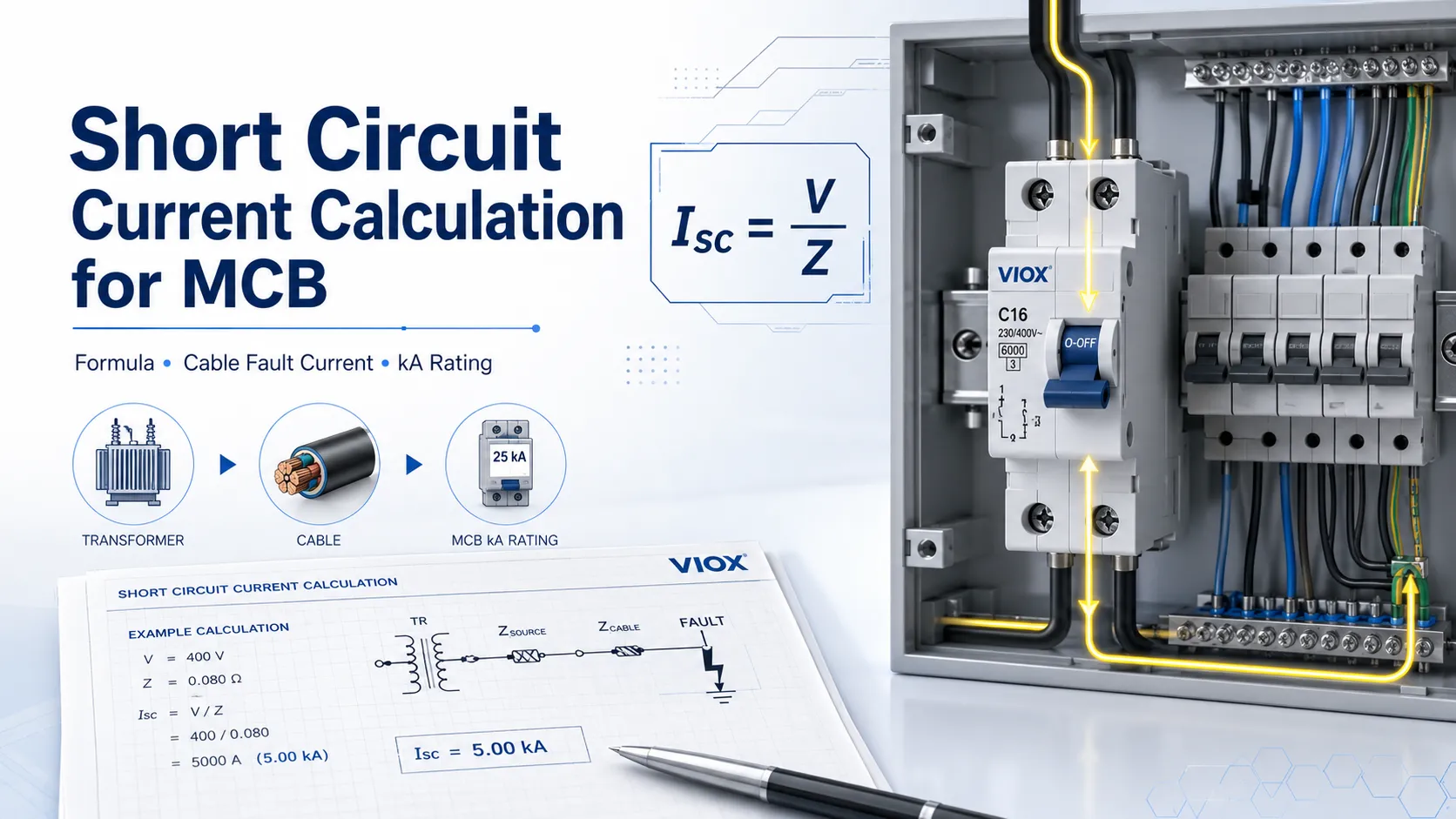
To calculate short-circuit current, divide the system voltage by the total impedance from the source to the fault point:
Short-circuit current (Isc) = Voltage (V) ÷ Total impedance (Ztotal)For MCB selection, the calculated prospective short-circuit current at the installation point must be lower than the MCB breaking capacity, such as 6 kA, 10 kA, or another value marked on the device. The breaker’s amp rating protects against overload. The kA breaking capacity protects against fault interruption failure.
In real installations, the key is not only the formula. You must know the transformer or supply fault level, cable impedance, cable length, earthing system, fault location, and whether you are calculating maximum or minimum fault current.
This guide is written for low-voltage MCB and distribution-board selection. It is suitable for preliminary engineering checks, panel-builder review, and buyer education. For utility networks, hospitals, data centers, generator systems, arc-flash studies, or multi-source industrial plants, use a qualified electrical engineer and recognized calculation software.
Quick Answer: Short Circuit Current Formula
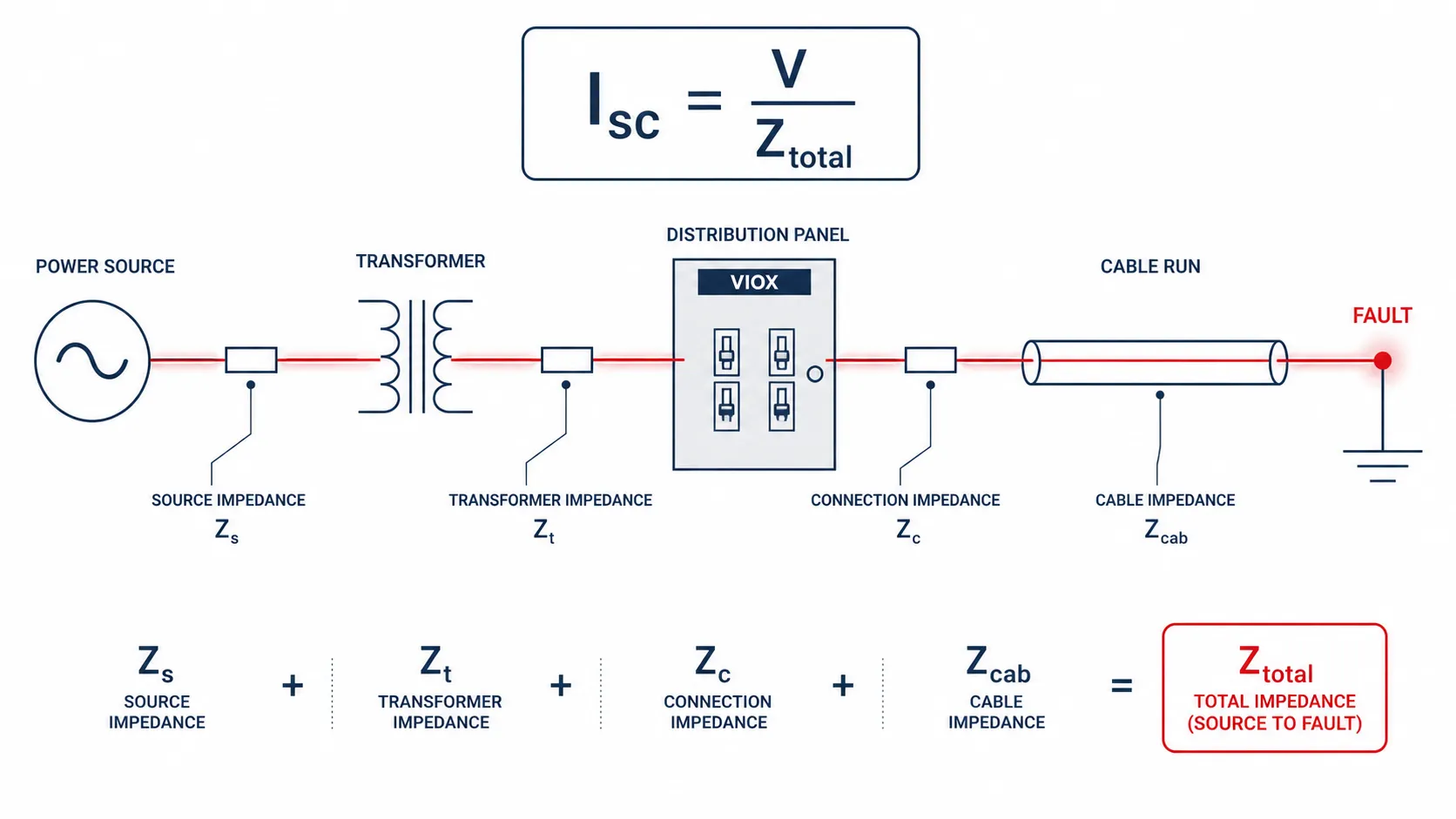
The basic short-circuit current formula is:
Short-circuit current (Isc) = Voltage (V) ÷ Impedance (Z)Where:
- (Isc) = prospective short-circuit current, in amperes
- (V) = system voltage at the fault point
- (Z) = total source and circuit impedance to the fault point, in ohms
For a three-phase fault using line-to-line voltage:
Three-phase fault current: Isc(3φ) = VLL ÷ (√3 × Zphase)For a single-phase line-to-neutral fault:
Single-phase fault current: Isc(1φ) = VLN ÷ ZloopIf you are using RMS voltage and RMS impedance values, the calculated result is already a symmetrical RMS fault current. Do not multiply it by 0.707 again.
Short Circuit Current Calculation at a Glance
| Situation | Formula or method | What it checks |
|---|---|---|
| Basic impedance method | (Isc = V ÷ Z) | Quick estimate when total impedance is known |
| Three-phase fault | (Isc(3φ) = VLL ÷ (√3 × Zphase)) | Maximum three-phase prospective fault current |
| Single-phase fault | (Isc(1φ) = VLN ÷ Zloop) | Line-to-neutral or line-to-earth loop fault current |
| Transformer terminal fault | (Isc = IFL × 100 ÷ Z%) | Available fault current near transformer secondary |
| Cable-end fault | Source fault current plus cable impedance | Minimum fault current and tripping-time check |
| Breaker kA rating | Compare PSCC with Icn, Icu, Ics, or interrupting rating | Whether the device can interrupt safely |
Short Circuit Current vs MCB Breaking Capacity
An MCB has two different ratings that are often confused:
| Rating | Meaning | Example |
|---|---|---|
| Amp rating | Continuous current rating for overload protection | 6 A, 10 A, 16 A, 20 A, 32 A |
| Breaking capacity | Maximum short-circuit current the MCB can safely interrupt under its product standard | 3 kA, 4.5 kA, 6 kA, 10 kA |
If the calculated prospective short-circuit current at the MCB location is 7 kA, a 6 kA MCB is not suitable. You need an MCB or protective device with a breaking capacity that meets the available fault current and the applicable local code or standard.
For common MCB amp ratings, see VIOX’s standard MCB sizes guide. For trip curve behavior, see the VIOX trip curve guide.
Icn, Icu, and Ics: Which kA Rating Are You Comparing?
The marking used for breaking capacity depends on the breaker standard and market.
| Marking | Common context | Meaning |
|---|---|---|
| Icn | IEC 60898-1 MCBs for household and similar installations | Rated short-circuit capacity used for many standard MCBs |
| Icu | IEC 60947-2 industrial circuit breakers | Ultimate short-circuit breaking capacity |
| Ics | IEC 60947-2 industrial circuit breakers | Service short-circuit breaking capacity, often expressed as a percentage of Icu |
| AIC / interrupting rating | North American context | Ampere interrupting capacity under applicable UL/NEC requirements |
When the search question is “calculate kA rating circuit breakers,” the practical answer is: calculate the available prospective short-circuit current at the installation point, then choose a protective device whose applicable interrupting or breaking capacity is not lower than that value under the relevant standard.
Manufacturer’s Insight: Why kA Rating Is Not Just a Label
From a manufacturer and panel-builder perspective, the kA marking on an MCB is the result of the whole interruption system, not a printing choice. Contact material, contact pressure, arc runner geometry, arc chute design, operating mechanism speed, terminal heat rise, and housing material all influence whether the device can interrupt a real short-circuit event without unacceptable damage.
For buyers, the practical lesson is simple: do not compare two MCBs only by amp rating and price. When available fault current is close to 6 kA, 10 kA, or higher, ask for the relevant datasheet, product standard, breaking-capacity marking, and test documentation for the exact model being supplied. This is especially important for OEM panels, export distribution boards, and installations near transformers where prospective short-circuit current can be much higher than expected.
Data You Need Before Calculation
Before calculating fault current, collect the following information.
| Data | Why It Matters |
|---|---|
| Supply voltage | Determines the driving voltage for the fault current |
| Transformer kVA and impedance | Major source impedance in low-voltage systems |
| Utility available fault current | Best starting point when supplied by utility data |
| Cable length | Longer cable increases impedance and lowers fault current |
| Cable size and material | Copper and aluminum have different impedance |
| Fault location | Fault current is highest near the source and lower at the cable end |
| Earthing system | Affects line-to-earth fault current path |
| Protective device rating | Must match calculated fault current |
| Standards/code context | IEC, NEC, or local rules may require specific methods |
If the installation is industrial, medical, data center, large commercial, or multi-source, use power system analysis software or a qualified electrical engineer rather than relying on a simplified hand calculation.
Method 1: Basic Impedance Calculation
The most universal concept is to add all impedance between the source and the fault point.
Ztotal = Zsource + Ztransformer + Zcable + ZconnectionsThen calculate:
Short-circuit current (Isc) = Voltage (V) ÷ Total impedance (Ztotal)Example
Assume a simple three-phase system:
- Line-to-line voltage: 400 V
- Equivalent phase impedance to fault point: 0.02 ohms
Using the three-phase formula:
Isc(3φ) = 400 ÷ (√3 × 0.02)Isc(3φ) ≈ 11,547 A = 11.5 kAThe prospective short-circuit current is about 11.5 kA. A 6 kA MCB would not be suitable at that point. A 10 kA MCB may also be insufficient if the calculated current exceeds 10 kA. The final device must be selected according to the exact system, standard, and coordination design.
Method 2: Transformer Short Circuit Current
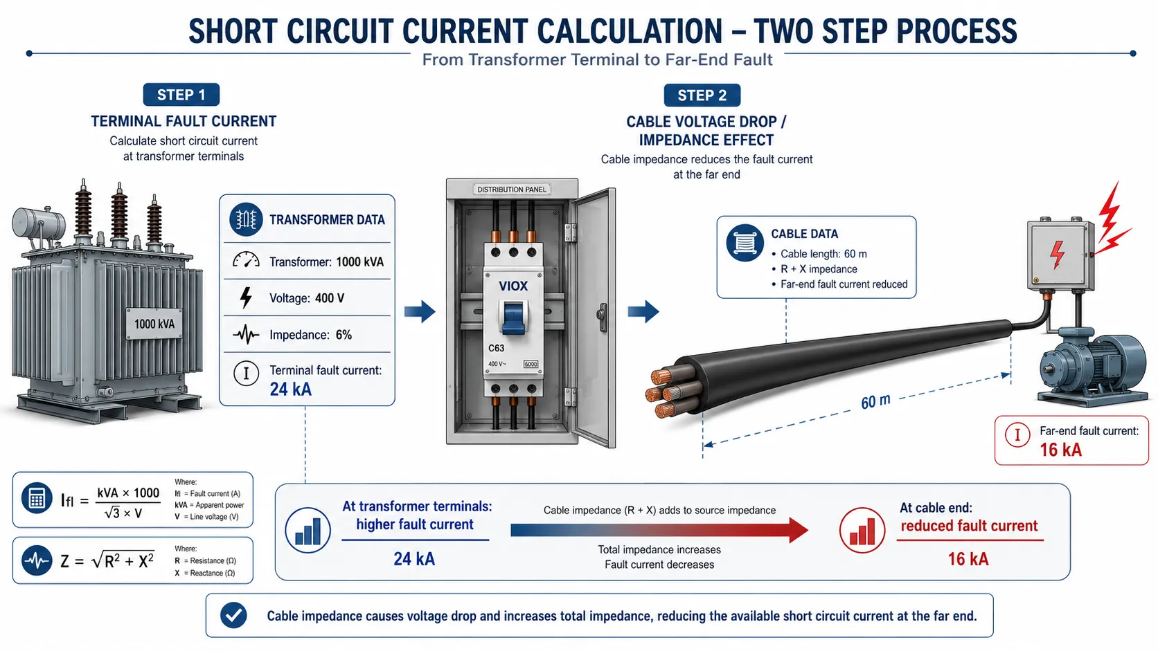
When the transformer is the main source, a quick estimate can be made from transformer kVA and percent impedance.
For a three-phase transformer:
Transformer full-load current: IFL = (kVA × 1000) ÷ (√3 × VLL)Then:
Transformer fault current: Isc = IFL × (100 ÷ Z%)Example
Assume:
- Transformer rating: 500 kVA
- Secondary voltage: 400 V
- Transformer impedance: 5%
Full-load current:
IFL = (500 × 1000) ÷ (√3 × 400) ≈ 722 AEstimated short-circuit current at transformer terminals:
Isc = 722 × (100 ÷ 5) ≈ 14,440 A = 14.4 kAAt the transformer terminals, the fault current is about 14.4 kA before cable impedance is added. At the end of a long cable, the fault current will be lower because cable impedance increases the total loop impedance.
Quick Transformer Fault Current Reference
The table below is a simplified reference only. It assumes a three-phase 400V transformer and does not include upstream utility impedance, cable impedance, motor contribution, or tolerance.
| Transformer | Impedance | Full-load current | Estimated terminal fault current |
|---|---|---|---|
| 100 kVA | 4% | 144 A | 3.6 kA |
| 250 kVA | 4% | 361 A | 9.0 kA |
| 500 kVA | 5% | 722 A | 14.4 kA |
| 1000 kVA | 6% | 1443 A | 24.1 kA |
This is why a 6 kA MCB may be acceptable in some final circuits but unsuitable near a large transformer or main distribution board.
Method 3: Cable Short Circuit Current Calculation
Cable impedance can significantly reduce fault current, especially in long final circuits. This matters for both breaker breaking capacity and magnetic trip operation.
For a simplified DC-style resistance estimate:
Cable resistance: R = ρ × (L ÷ A)Where:
- (R) = conductor resistance
- (ρ) = conductor resistivity
- (L) = conductor length
- (A) = conductor cross-sectional area
For AC short-circuit calculation, cable reactance and temperature-adjusted resistance may also be relevant. Professional calculations use cable impedance tables rather than only simple resistance.
For small final circuits, resistance often dominates and a simplified resistance-based estimate can be useful for early checks. For larger cables, long feeders, parallel runs, or more rigorous engineering studies, cable impedance should be treated as a vector quantity:
Cable impedance: Z = √(R² + X²)Where (R) is resistance and (X) is reactance. In professional calculations, source impedance, transformer impedance, cable impedance, motor contribution, and earthing path impedance are normally handled as complex values rather than simple scalar additions.
Why Cable Calculation Matters
There are two different concerns:
- Maximum short-circuit current near the source: checks MCB breaking capacity.
- Minimum fault current at the far end of the cable: checks whether the breaker trips fast enough.
This is where many simplified online calculations fail. A high fault current can exceed the breaker’s breaking capacity near the supply, while a low fault current at the cable end can fail to trip the magnetic element quickly.
For cable sizing and voltage drop context, see VIOX’s IEC cable sizing guide.
Cable Short Circuit Calculation Example
Assume a simplified single-phase final circuit where resistance dominates:
- Line-to-neutral voltage: 230 V
- Source plus transformer equivalent impedance: 0.035 ohms
- Cable loop impedance to the load end: 0.45 ohms
Approximate loop impedance:
Zloop = 0.035 Ω + 0.45 Ω = 0.485 ΩEstimated fault current at the cable end:
Isc = 230 ÷ 0.485 ≈ 474 AThis value may be far lower than the fault current at the panel. The panel-end fault current may be used for breaking-capacity checks, while the far-end fault current is important for trip-time verification.
This example intentionally uses scalar addition to keep the method readable. For larger conductors or formal project documentation, use impedance tables or software that separates resistance and reactance.
Prospective Short Circuit Current Calculation
Prospective short-circuit current, or PSCC, is the fault current that could flow before the protective device operates. It is “prospective” because it is calculated from system voltage and impedance, not measured by intentionally creating a short circuit.
PSCC is used to check:
- MCB breaking capacity
- Fuse interrupting capacity
- Panel SCCR
- Arc-flash energy studies
- Protective device coordination
- Cable withstand
- Fault clearing time
Never measure PSCC by shorting conductors. Use calculation, utility data, design software, or appropriate test instruments designed for fault-loop or prospective current measurement.
How to Calculate kA Rating for Circuit Breakers
The breaker kA rating must be greater than or equal to the prospective short-circuit current at the point where the breaker is installed, using the applicable standard and local code requirements.
| Calculated PSCC at MCB Location | Minimum Breaking Capacity Concept |
|---|---|
| 3.2 kA | A 4.5 kA or 6 kA device may be considered if otherwise suitable |
| 5.8 kA | A 6 kA device is close; verify standard, tolerance, and design margin |
| 7.5 kA | Use a device rated above 7.5 kA, commonly 10 kA or higher |
| 12 kA | 10 kA is insufficient; select higher-rated protection |
Do not use an arbitrary universal safety margin such as 25% as a substitute for code, standard, and engineering review. The required device rating depends on the installation, applicable rules, manufacturer data, coordination, and future system changes.
Maximum vs Minimum Short Circuit Current
A useful short-circuit study normally considers both maximum and minimum fault current.
| Calculation type | Where it usually occurs | Why it matters |
|---|---|---|
| Maximum short-circuit current | Near transformer, utility service, main distribution board | Checks breaker breaking capacity, panel SCCR, busbar withstand, arc energy |
| Minimum fault current | End of long cable, high-impedance loop, remote final circuit | Checks whether MCB magnetic trip or protective device clearing time is fast enough |
For MCB selection, this distinction is critical. A high fault current near the source may exceed a 6 kA device, while a low fault current at the end of a long cable may fail to operate the instantaneous magnetic trip of a Type C or Type D MCB.
Symmetrical RMS Current, Peak Current, and Making Capacity
Most simplified calculations produce symmetrical RMS short-circuit current. This is the value commonly compared with breaker interrupting or breaking capacity.
In real AC systems, the first fault cycle may include a DC offset, creating a higher asymmetrical peak current. This affects mechanical and electrodynamic stress on contacts, busbars, and breaker mechanisms.
For industrial circuit breakers under IEC 60947-2, you may also see Icm, the rated short-circuit making capacity. For standard MCB selection, buyers usually focus first on the marked kA breaking capacity, but engineers should be aware that peak and making-current withstand become important in larger panels and assemblies.
MCB Tripping Time vs Short Circuit Current
Short-circuit current calculation also affects tripping time.
An MCB has:
- A thermal trip region for overloads
- A magnetic trip region for short circuits
For example, Type B, C, and D curves have different magnetic trip thresholds. A Type C breaker may require a higher fault current to trip instantaneously than a Type B breaker. If the cable is long and the fault current at the far end is too low, the breaker may not trip within the required time.
This is why “MCB tripping time calculation” is not only about the breaker. It also depends on cable impedance, supply impedance, trip curve, grounding system, and fault type.
B, C, and D Curve Check
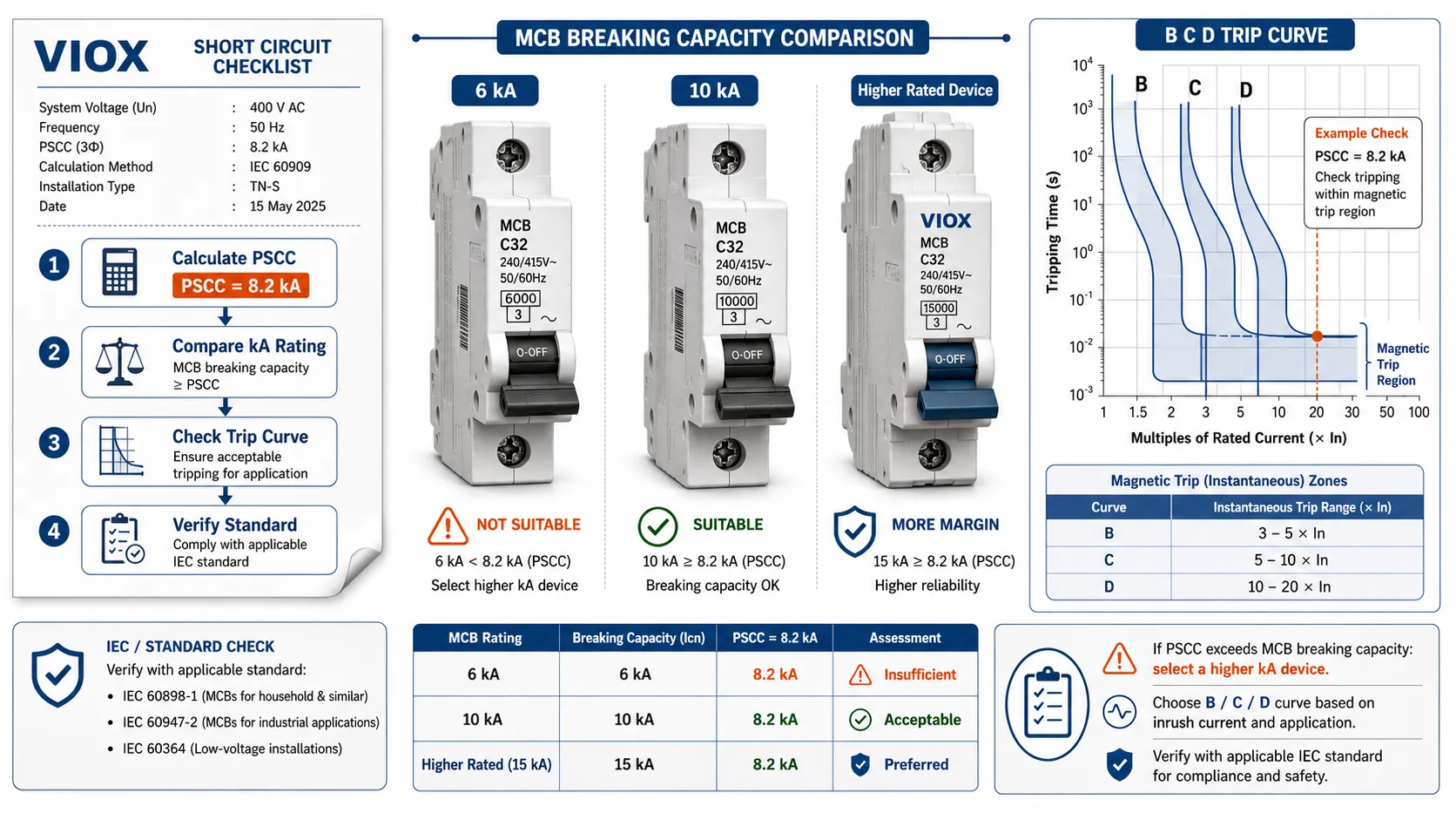
MCB curve selection affects whether a calculated fault current falls into the instantaneous magnetic trip region.
| MCB curve | Typical magnetic trip range | Practical implication |
|---|---|---|
| Type B | 3 to 5 times rated current | Easier to trip at lower fault current; common for resistive/light final circuits |
| Type C | 5 to 10 times rated current | Handles moderate inrush; needs higher fault current for instant trip |
| Type D | 10 to 20 times rated current | Used for high inrush loads; requires much higher fault current for instant trip |
Example: a 16A Type C MCB may need roughly 80A to 160A to enter the instantaneous magnetic region. If the far-end fault current is below the required threshold, disconnection may rely on the thermal region and may be too slow for the intended protection requirement.
Use the manufacturer’s trip curve and the applicable wiring rule for final verification.
Short Circuit Current and SCCR
Short-circuit current calculation also supports SCCR review. SCCR is the short-circuit current rating of equipment or a panel assembly, while breaker breaking capacity is the ability of a protective device to interrupt a fault.
If the available fault current is higher than the SCCR of a control panel, the panel is not suitable for that installation point even if the branch MCB has a high breaking capacity.
For panel-level safety, see VIOX’s SCCR guide.
Short Circuit Current Calculator Inputs
If you create a spreadsheet or online calculator for this topic, it should ask for the following inputs rather than only voltage and one impedance value.
| Calculator input | Why it is needed |
|---|---|
| System type | Single-phase or three-phase formula selection |
| Voltage | Line-to-line or line-to-neutral voltage |
| Transformer kVA | Determines full-load current |
| Transformer impedance percentage | Determines transformer terminal fault current |
| Utility available fault current | Improves accuracy when transformer is not the only source |
| Cable size and material | Determines cable impedance |
| Cable length | Determines voltage drop and fault-current reduction |
| Fault location | Main board, sub-board, or final circuit end |
| MCB curve and amp rating | Needed for tripping-time check |
| MCB breaking capacity | Needed for kA rating comparison |
This structure aligns better with how engineers actually calculate prospective short-circuit current than a one-line calculator that simply divides voltage by a guessed impedance.
Common Short Circuit Calculation Mistakes
Mistake 1: Using the Load Current Formula
Load current and short-circuit current are not the same. Load current depends on power demand. Short-circuit current depends mainly on voltage and impedance.
Mistake 2: Forgetting Cable Impedance
Ignoring cable impedance can overestimate short-circuit current at the far end. This can hide a tripping-time problem.
Mistake 3: Confusing Line-to-Line and Line-to-Neutral Voltage
Use the correct voltage for the fault type. Three-phase and single-phase formulas are not identical.
Mistake 4: Applying 0.707 Incorrectly
If you use RMS voltage and impedance, the short-circuit current result is already an RMS symmetrical value. Do not multiply by 0.707 again.
Mistake 5: Treating MCB kA Rating as Panel SCCR
The breaker’s breaking capacity is not the same as the SCCR of a control panel or assembly.
Mistake 6: Ignoring Minimum Fault Current
Maximum fault current checks breaking capacity. Minimum fault current checks whether the protective device trips fast enough at the farthest point.
Mistake 7: Using Typical Fault Current Tables as Design Values
Typical values can help with early estimates, but they cannot replace transformer data, utility data, cable impedance, and project-specific calculation. A 10 kA MCB is not automatically suitable because a table says a building is “light commercial.”
Quick Calculation Checklist
| Step | Check |
|---|---|
| 1 | Define fault location: source, panel, branch circuit, or cable end |
| 2 | Identify fault type: three-phase, line-to-line, line-to-neutral, or line-to-earth |
| 3 | Gather source or transformer fault data |
| 4 | Add cable impedance to the fault point |
| 5 | Calculate maximum PSCC for breaking capacity |
| 6 | Calculate minimum fault current for trip time where required |
| 7 | Compare breaker kA rating with calculated PSCC |
| 8 | Check trip curve and disconnection time |
| 9 | Document assumptions, cable data, and calculation date |
| 10 | Use professional software or engineering review for complex systems |
FAQ
What is the formula for short circuit current?
The basic formula is (Isc = V ÷ Z), where (V) is system voltage and (Z) is total impedance to the fault point. For three-phase faults, use (Isc(3φ) = VLL ÷ (√3 × Zphase)).
How do you calculate short circuit current for a circuit breaker?
Calculate the prospective short-circuit current at the breaker location using source, transformer, and cable impedance. Then select a breaker with breaking capacity equal to or greater than that fault current according to the applicable code and standard.
What is prospective short circuit current?
Prospective short-circuit current is the current that could flow during a fault before the protective device operates. It is based on available voltage and system impedance.
How does cable length affect short circuit current?
Longer cable increases impedance, which reduces fault current at the load end. This may help breaking capacity but can create a tripping-time problem if the fault current becomes too low.
What is cable short circuit calculation?
Cable short-circuit calculation estimates how cable impedance changes the fault current at a specific point in the circuit. For long cables, it is especially important because the far-end fault current can be much lower than the fault current at the distribution board.
Is MCB breaking capacity the same as amp rating?
No. Amp rating is the continuous load current rating, such as 16 A or 32 A. Breaking capacity is the maximum fault current the MCB can safely interrupt, such as 6 kA or 10 kA.
Can I measure short circuit current with a multimeter?
No. Do not attempt to measure short-circuit current by shorting a circuit. Use calculation, utility fault data, loop impedance testers, or professional power system analysis tools.
What happens if short circuit current exceeds MCB breaking capacity?
The MCB may fail to interrupt the fault safely. This can cause arcing, fire, enclosure damage, or explosive failure.
What is the difference between fault current and short circuit current?
Short-circuit current is a type of fault current caused by an unintended low-impedance connection between conductors or from a conductor to earth. Fault current is the broader term and may include earth faults, line-to-line faults, line-to-neutral faults, and three-phase faults.
Can I calculate MCB tripping time from short circuit current?
You can estimate whether the fault current reaches the magnetic trip region by comparing the calculated current with the MCB trip curve. Exact tripping time must be taken from the manufacturer’s time-current curve and checked against the applicable wiring rules.
Which standard is used for short circuit current calculation?
IEC 60909 is widely used for short-circuit current calculation in IEC-based systems. IEEE methods are commonly used in North American power system studies. MCB product standards such as IEC 60898-1 and IEC 60947-2 define breaker testing and ratings, not the entire system calculation by themselves.
Conclusion
Short-circuit current calculation is the foundation for safe MCB selection. The main formula is simple: fault current equals voltage divided by total impedance. The engineering work is in finding the correct impedance, choosing the right fault location, and comparing the result with the breaker’s kA breaking capacity.
For reliable protection, calculate both maximum prospective short-circuit current and minimum fault current where required. Maximum fault current checks whether the breaker can interrupt safely. Minimum fault current checks whether the breaker trips fast enough at the end of the circuit.
Do not select an MCB only by amp rating. Match amp rating, voltage rating, trip curve, breaking capacity, cable impedance, and the installation standard as one protection system.