On this page
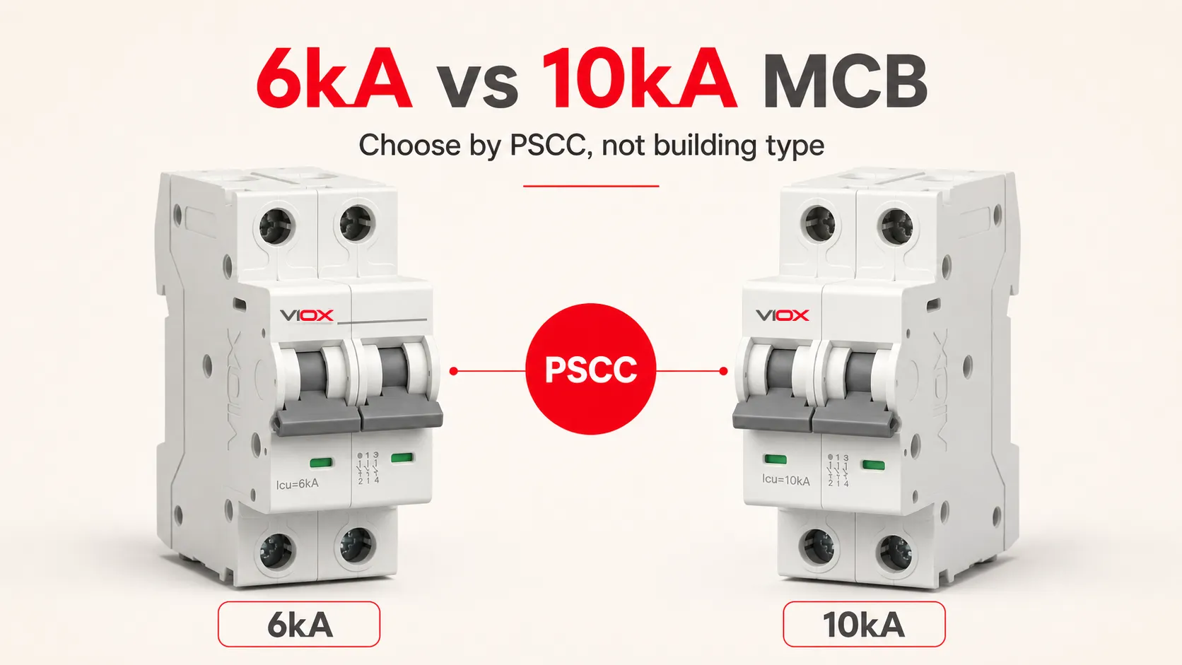
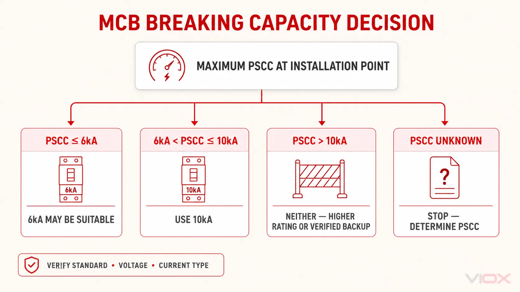
Choose between a 6kA and 10kA miniature circuit breaker (MCB) by comparing its applicable short-circuit rating with the maximum prospective short-circuit current (PSCC) at the exact installation point. Use a 6kA MCB only when its declared 6kA rating—under the applicable standard, voltage, and current type—is at least equal to the PSCC. If PSCC exceeds 6kA but does not exceed an applicable 10kA rating, use the 10kA device. If PSCC exceeds 10kA, neither is independently adequate unless an exact manufacturer-verified backup or cascading combination permits the application.
Residential, commercial, urban, rural, single-phase, three-phase, and distance-from-transformer labels can indicate where higher fault current may be more likely. They do not replace a calculation, measurement, utility value, or documented engineering study.
Safety boundary: Breaking-capacity selection is part of short-circuit protection design. Final selection must be made or verified by a qualified electrical professional using the applicable installation rules, project requirements, assembly documentation, and current manufacturer data.
Key Takeaways
- 6kA and 10kA are short-circuit interruption ratings, not normal load-current ratings. A C20 MCB may be rated 20A for its circuit-current function and 6kA or 10kA for a defined short-circuit test.
- The correct comparison is rating versus PSCC at the installation point. 6kA is not automatically “residential,” 10kA is not automatically “commercial,” and building type or transformer distance cannot replace fault-current evidence.
- Compare values under the same conditions. Check the product standard, rated voltage, AC or DC application, pole arrangement, and exact manufacturer declaration.
- A higher kA rating does not make the MCB trip faster. Trip curve and breaking capacity answer different questions.
- Backup protection must be documented for the exact device combination. An upstream breaker or fuse does not automatically increase a downstream MCB’s permitted short-circuit application.
Quick 6kA vs 10kA Decision Matrix
Use this matrix only after identifying an applicable rating at the actual system voltage.
| Maximum PSCC at the MCB location | 6kA MCB | 10kA MCB | Decision |
|---|---|---|---|
| PSCC is at or below 6kA | May be suitable | May also be suitable | Verify standard, voltage, current type, installation rules, and all other MCB ratings |
| PSCC is above 6kA but at or below 10kA | Not independently adequate | May be suitable | Use an applicable 10kA device or an explicitly verified backup arrangement |
| PSCC is above 10kA | Not independently adequate | Not independently adequate | Select a higher-capacity device or a manufacturer-verified protective combination |
| PSCC is unknown | Cannot be confirmed | Cannot be confirmed | Obtain utility data, calculate, measure with an appropriate instrument, or commission an engineering study |
| A backup/cascading arrangement is proposed | Do not judge the downstream MCB alone | Do not judge the downstream MCB alone | Verify the exact upstream/downstream catalogue numbers, voltage, fault level, and manufacturer table |
This table addresses breaking capacity only. Rated current, trip characteristic, conductor protection, disconnection time, selectivity, energy limitation, enclosure compatibility, and local rules require separate checks. The broader MCB selection guide covers those adjacent decisions.
What Do 6kA and 10kA Mean on an MCB?
One kiloampere is 1,000 amperes. A 6kA marking therefore refers to 6,000A, and a 10kA marking refers to 10,000A. On an MCB, the marked value commonly identifies a short-circuit capacity declared under a specified product standard and at specified electrical conditions.
It does not mean:
- the MCB carries 6,000A or 10,000A continuously, or that 10kA trips faster than 6kA;
- the value applies at every voltage, to both AC and DC, or automatically to the completed distribution board;
- the device remains suitable after any fault up to the number without inspection or following manufacturer instructions;
- 10kA can replace 6kA without checking the remaining ratings and compatibility.
For a cross-standard explanation of kA, AIC, and SCCR terminology, see what the kA rating on a circuit breaker means.
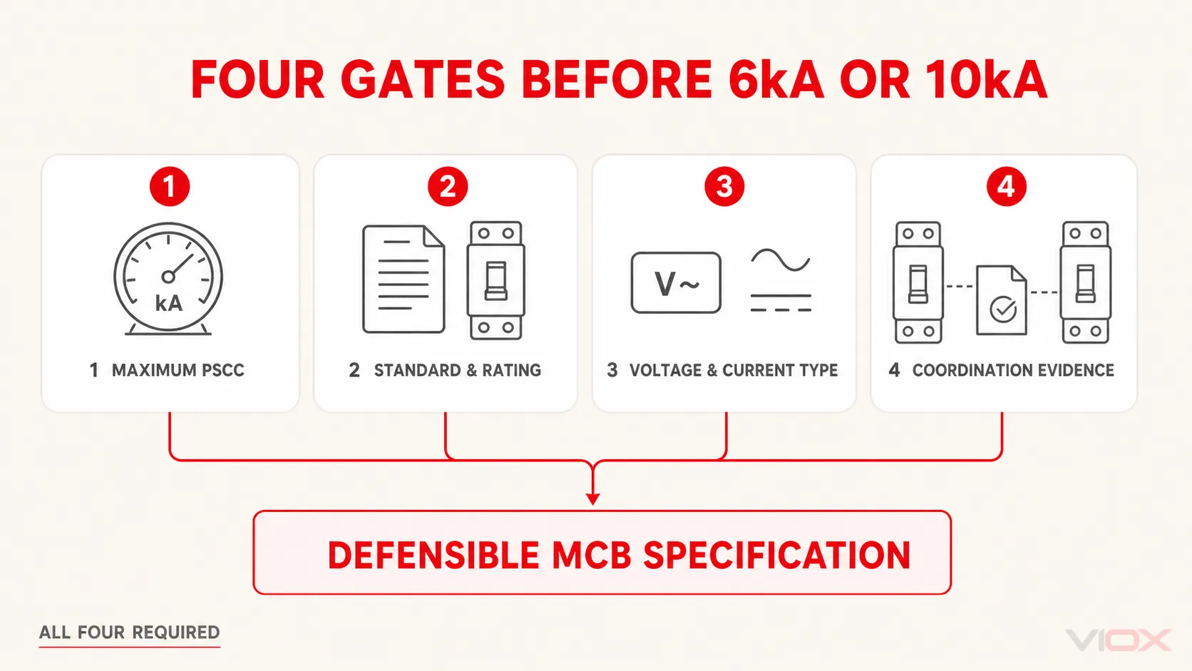
The Four Gates That Decide Between 6kA and 10kA
A defensible MCB breaking-capacity specification must pass all four gates. Physical fit or a larger number on the front does not complete the decision.
| Gate | Required evidence | Why it changes the decision |
|---|---|---|
| 1. Maximum PSCC | Utility fault-current data, a recognized calculation, an appropriate measurement, or an engineering study | Establishes the fault current the MCB may have to interrupt at its location |
| 2. Rating designation and standard | Exact device marking, datasheet, certificate or declaration, and applicable product standard | Icn, Icu, Ics, and North American interrupting ratings are not interchangeable labels |
| 3. Voltage and current type | Rating table for the exact model at the actual AC or DC voltage | Breaking capacity may change with voltage and current type |
| 4. Coordination evidence | Manufacturer backup/cascading or series-rating table for the exact combination | Determines whether an upstream protective device changes the permitted downstream application |
If any gate is unresolved, the selection is incomplete. Do not replace the missing evidence with a building-category assumption.
Icn, Icu, and Ics: Compare the Correct Rating
The physical size of a breaker does not determine which short-circuit term applies. Read the standard and rating marked or declared for the exact device.
| Rating | Standards context | Practical use in this decision |
|---|---|---|
| Icn | Rated short-circuit capacity used for circuit breakers within IEC 60898-1 | Compare the declared Icn at the applicable voltage with PSCC when IEC 60898-1 governs the product application |
| Icu | Rated ultimate short-circuit breaking capacity under IEC 60947-2 | Use only within the IEC 60947-2 declaration and its stated voltage and conditions |
| Ics | Rated service short-circuit breaking capacity under IEC 60947-2 | Review together with Icu where post-short-circuit service capability and project requirements matter |
IEC 60898-1 covers AC air-break circuit breakers within its stated household-and-similar scope, including limits on rated voltage, current, and short-circuit capacity. IEC 60947-2:2024 applies to circuit breakers within its stated low-voltage scope that are intended to be installed and operated by instructed or skilled persons.
Do not simplify this into “IEC 60898-1 is always residential and IEC 60947-2 is always industrial.” The applicable standard depends on the product declaration, installation context, market requirements, and persons expected to install and operate the equipment. Some breakers carry declarations under more than one standard, and the numerical short-circuit ratings may differ. Compare the value that applies to the actual design—not the most favorable number printed in unrelated conditions.
For a deeper standards crosswalk, use the guide to IEC 60898-1 versus IEC 60947-2. For the detailed relationship among Icu, Ics, Icw, and Icm, use the separate circuit-breaker ratings guide.
6kA vs 10kA MCB: Decision-Relevant Differences
| Selection point | 6kA MCB | 10kA MCB |
|---|---|---|
| Declared short-circuit value | 6,000A under the stated standard and conditions | 10,000A under the stated standard and conditions |
| Effect on overload rating | None by itself | None by itself |
| Effect on B, C, or D instantaneous characteristic | None by itself | None by itself |
| Automatic application category | None | None |
| Direct interchangeability | Must still match voltage, poles, trip curve, current rating, terminals, mounting, approvals, and assembly system | The higher kA number alone does not prove interchangeability |
A 10kA MCB has greater declared short-circuit interruption capability than an otherwise comparable 6kA MCB under corresponding conditions. That is the bounded advantage. It does not prove better selectivity, lower let-through energy, faster tripping, broader certification, longer service life, or compatibility with the existing panel.
How to Select MCB Breaking Capacity in Five Steps
Step 1: Define the Exact Installation Point
PSCC is location-specific. Define whether the MCB is at the service entrance, a distribution board, a machine panel, or an end circuit, then record the system voltage, AC or DC application, earthing arrangement, sources, transformer or generator data, conductor path, and relevant motor contribution. Multi-source systems require particular care because a single-source estimate may miss a contribution.
Step 2: Determine the Maximum PSCC at That Point
Use the method required by the applicable installation rules and project. Depending on the system, that may involve:
- an available-fault-current value from the utility;
- a calculation using source, transformer, conductor, connection, and fault-loop impedance;
- measurement with an instrument and procedure suitable for the installation;
- a power-system study for industrial, generator, parallel-source, medical, data-center, or other complex systems.
The simplified relationship is based on voltage divided by the relevant total impedance, but the correct voltage, impedance model, fault type, tolerances, and source contributions depend on the system. Use the dedicated guide to calculate short-circuit current for MCB selection rather than treating one generic formula as universally sufficient.
Step 3: Identify the Exact MCB Declaration
From the nameplate and current datasheet, confirm:
- the exact catalogue number and applicable product standard;
- the Icn, Icu, Ics, or other interrupting-rating designation at the actual voltage and current type;
- the rated current, trip characteristic, pole arrangement, and relevant wiring restrictions;
- whether the stated capacity is independent or conditional on a documented protective combination.
Do not transfer a value from a related model, another voltage column, a similar enclosure, or a reseller description.
Step 4: Compare Like with Like
Apply the decision matrix above using the rating declared under the same product-standard, voltage, and current-type conditions as the installation. Local rules, project specifications, utility requirements, or assembly documentation may impose a higher minimum and take precedence over the basic comparison.
Do not introduce an arbitrary universal percentage margin. Calculation uncertainty, source changes, tolerances, and future network modifications should be handled by the engineering method and requirements applicable to the project.
Step 5: Verify the Rest of the Protective Design
Passing the kA comparison does not complete MCB selection. Verify rated current, trip curve, conductor protection and disconnection time, temperature effects, selectivity, energy limitation, pole function, terminals, and distribution-board approval. The individual MCB rating does not automatically establish the rating of the completed panel.
Why Building Type and Transformer Distance Are Not Selection Rules
Fault current is often higher close to a low-impedance source and often decreases as conductor impedance is added downstream. Larger transformers and strong utility networks can also increase available fault current. These are valid engineering relationships, but they do not produce a universal distance-to-kA table.
Two panels at the same transformer distance can still have different PSCC because of:
- transformer kVA and percentage impedance;
- upstream utility source impedance;
- conductor material, cross-section, length, and parallel paths;
- generator, motor, or other source contribution;
- system voltage and fault type;
- connection and busbar impedance;
- the exact point at which the fault is evaluated.
Likewise, future load growth does not necessarily increase short-circuit current. Adding ordinary loads is different from changing the transformer, generator, conductor network, or utility source. “Future-proofing” therefore requires a documented source and network scenario, not an automatic upgrade from 6kA to 10kA.
Three Bounded Selection Examples
These examples demonstrate the decision logic only. They do not replace a system study or confirm any particular product.
| Verified design input | Breaking-capacity result | Remaining checks |
|---|---|---|
| Maximum PSCC is 4.2kA; an IEC 60898-1 MCB declares Icn 6kA at the actual system voltage | The 6kA device meets the basic rating-versus-PSCC comparison; a 10kA device may also meet it | Local rules, current rating, curve, conductor protection, assembly compatibility, and coordination |
| Maximum PSCC is 7.4kA; candidate MCBs declare applicable Icn values of 6kA and 10kA | The 6kA device is not independently adequate; the 10kA candidate may be suitable | Verify all other ratings and installation conditions |
| Maximum PSCC is 11.5kA; the highest independent candidate rating is 10kA | Neither candidate is independently adequate | Select a higher-rated device or verify an exact manufacturer backup/cascading combination |
Notice that none of these decisions depends on whether the building is called residential or commercial. The electrical values and applicable evidence control the result.
Can Backup Protection Allow a Lower-Rated Downstream MCB?
Possibly—but only when the manufacturer has verified and documented the exact protective-device combination. Backup protection, also called cascading in some IEC contexts, uses an upstream current-limiting protective device to support the downstream device under defined short-circuit conditions.
Verify all of the following:
- exact upstream and downstream manufacturer references;
- system voltage and AC/DC conditions;
- maximum permitted prospective fault current;
- poles and system arrangement;
- any restrictions on installation, conductors, or accessories;
- the current manufacturer coordination table and applicable assembly requirements.
Do not combine ratings arithmetically, infer compatibility from two separate datasheets, or assume that any upstream fuse or breaker protects any downstream MCB.
Backup protection and selectivity are also different questions. Backup protection concerns safe short-circuit capability of the combination. Selectivity concerns which device operates for a given fault. A combination may provide backup protection without providing full selectivity across the same current range.
Nameplate, Datasheet, and RFQ Checklist
Before approving a 6kA or 10kA MCB, record the following in the design or purchasing file:
| Item to record | Required source |
|---|---|
| Maximum PSCC at the installation point | Utility data, calculation, measurement, or study |
| Required breaking-capacity designation | Applicable standard and project requirements |
| MCB manufacturer and catalogue number | Product marking and current datasheet |
| Declared Icn, Icu, Ics, or interrupting rating | Exact rating table |
| Voltage and AC/DC conditions for the rating | Nameplate and datasheet |
| Rated current, trip curve, and poles | Circuit design and device data |
| Independent or conditional rating | Product and coordination documentation |
| Upstream/downstream combination, if used | Current manufacturer backup/cascading table |
| Panel or distribution-system compatibility | Assembly manufacturer documentation |
| Required approvals and market documentation | Procurement specification and supplier evidence |
For sourcing, compare exact declarations rather than asking only for “a 10kA MCB.” VIOX can review an MCB requirement when the request includes the system voltage, applicable standard, pole arrangement, current rating, trip curve, required breaking capacity, and target-market documentation. See the VIOX MCB product range after the engineering requirements have been defined.
Frequently Asked Questions
Is a 10kA MCB better than a 6kA MCB?
It has a higher declared short-circuit capacity under corresponding stated conditions. It is not universally better. If both ratings exceed the PSCC, the decision must still consider standard, voltage, current rating, trip curve, energy limitation, selectivity, assembly compatibility, availability, and project requirements.
Can I replace a 6kA MCB with a 10kA MCB?
Not based on the kA value alone. Confirm manufacturer and system compatibility, rated voltage, current rating, trip characteristic, poles, terminal arrangement, dimensions, busbar fit, approvals, and any assembly restrictions. Never mix breaker families in a distribution board unless the assembly documentation permits the combination.
Does a three-phase system always require a 10kA MCB?
No. Phase count alone does not determine PSCC or the required breaking capacity. Calculate or otherwise determine the maximum relevant fault current at the installation point and compare it with the device rating under the applicable voltage and standard conditions.
Does a Type C MCB have a higher breaking capacity than a Type B MCB?
Not necessarily. B, C, and D identify instantaneous tripping characteristics under an IEC-style marking system; 6kA or 10kA identifies a short-circuit capacity under stated conditions. Check both ratings independently. The circuit-breaker trip curve guide explains the trip-characteristic boundary.
What should I do if the PSCC is unknown?
Do not confirm either rating. Obtain utility data, perform an appropriate calculation or measurement, or commission a system study. The required method depends on the installation and applicable rules.
Can a 10kA MCB be used where PSCC exceeds 10kA?
Not as an independently rated device. It may be permitted only as part of an exact manufacturer-verified backup, cascading, or series-rated combination under the documented conditions. Otherwise, select a device with a higher applicable breaking capacity.
Primary Technical Sources
- IEC 60898-1:2015+AMD1:2019 CSV — Circuit-breakers for overcurrent protection for household and similar installations
- IEC 60947-2:2024 — Low-voltage switchgear and controlgear — Circuit-breakers
- VIOX: Short-Circuit Current Calculation for MCB Selection
Always verify the edition required by the project or jurisdiction and the current technical documentation for the exact MCB and protective-device combination.