
The main difference between contactors and relays is their current capacity and application scope: contactors are heavy-duty electromagnetic switches designed for high-current loads (typically above 9 amperes) like motors and HVAC systems, while relays are precision switches for low-current control circuits (typically under 10 amperes) and signal switching. Choosing the correct device ensures electrical safety, code compliance, and prevents equipment failure.
Understanding this distinction is critical for industrial engineers, electrical contractors, and facility managers. Incorrect selection leads to welded contacts, nuisance failures, and potential code violations under NEC Article 430. This guide clarifies when to use each device, how to size them properly, and how to integrate them into compliant electrical systems.
What Are Contactors and Relays?
Contactor Definition
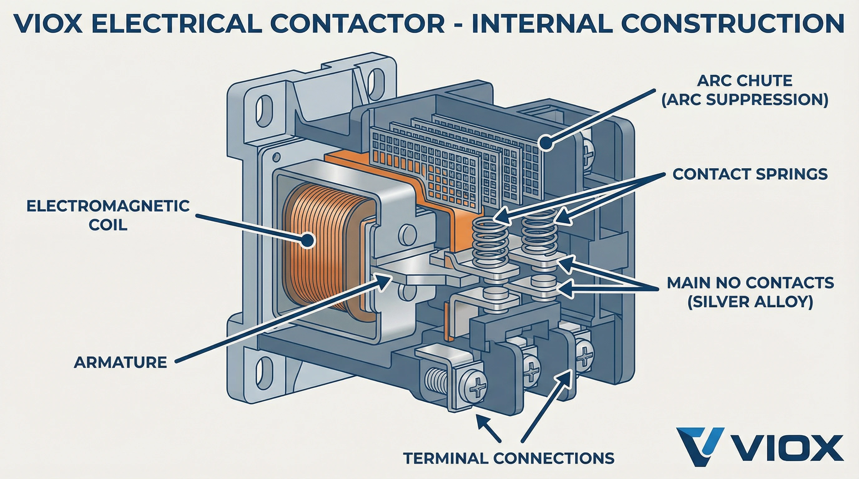
A contactor is an electrically controlled switch that connects and disconnects high-power load circuits—most commonly three-phase motors, large fans, HVAC compressors, and industrial heating elements. Contactors are designed for frequent switching under load with built-in arc suppression mechanisms.
Key characteristics:
- Heavy-duty construction with silver alloy or tungsten contacts
- Normally-open (NO) main contacts that fail-open on control power loss
- Built-in arc chutes for safe interruption of high-energy circuits
- Current ratings from 9 amperes to over 1000 amperes
- Designed per IEC 60947-4-1 and UL 508 standards
 and auxiliary contacts for industrial motor control applications.png)
Relay Definition
A relay is an electromagnetic switching device that uses a small control signal to operate contacts controlling separate circuits. Relays excel in control logic, automation interfaces, and signal switching where precision and compact size are required.
Key characteristics:
- Compact construction optimized for DIN rail or PCB mounting
- Multiple contact configurations: SPDT, DPDT, NO, NC, changeover
- Current ratings typically 0.1 to 10 amperes
- Fast switching speed (1-20 milliseconds)
- Designed per IEC 61810 and UL 508 standards
Key Differences: Contactors vs Relays
Comprehensive Comparison Table
| Feature | Contactors | Relays |
|---|---|---|
| Current Rating | 9-1000+ amperes | 0.1-10 amperes |
| Primary Application | Power circuit switching | Control circuit switching |
| Contact Configuration | NO main contacts + auxiliary | NO, NC, SPDT, DPDT options |
| Arc Suppression | Built-in arc chutes | Minimal or none |
| Physical Size | Large (3-12 inches) | Compact (0.5-3 inches) |
| Voltage Rating | 120V-1000V AC | 5V-480V AC/DC |
| Switching Speed | Moderate (50-100ms) | Fast (1-20ms) |
| Cost Range | $50-500+ | $5-100 |
| Typical Standards | IEC 60947-4-1, UL 508 | IEC 61810, UL 508 |
| Mechanical Life | 1-10 million operations | 10-100 million operations |
Load Capacity and Voltage
The primary distinction lies in current-handling capacity. Contactors handle high inrush currents typical of motor starting—often 6-8 times the running current. Relays cannot withstand these conditions and will weld or fail prematurely if misapplied to power circuits.
Contactors are built for three-phase AC power systems up to 1000V. Relays serve single-phase or low-voltage DC/AC control circuits. Motor applications always require contactors for the main power path, not relays.
Arc Energy Management
When switching high-current loads, electrical arcs form between opening contacts. Contactors incorporate arc chutes—metal barriers that divide, cool, and extinguish arcs safely. This feature is absent in relays, making them unsuitable for high-energy interruption.
Relays require external suppression (flyback diodes, RC snubbers) when switching inductive control loads. Without suppression, contact life decreases rapidly.
Contact Configuration and Auxiliary Functions
Contactors typically feature NO main contacts plus auxiliary contacts for status indication and interlocking. This configuration provides fail-safe behavior—loss of control power opens the circuit.
Relays offer flexible contact forms (NO, NC, changeover) essential for control logic. A single relay can simultaneously make and break multiple circuits, enabling complex automation sequences.
Applications and Use Cases
When to Use Contactors
Three-Phase Motor Control
Motor starting is the classic contactor application. NEC Article 430 requires proper motor circuit protection including overload devices and branch-circuit short-circuit protection. Contactors serve as the controlled switching element in motor starters.
- Pumps and compressors: 5-200 HP industrial motors
- Conveyor systems: frequent start/stop duty cycles
- Machine tools: coordinated multi-motor control
- Fans and blowers: HVAC and industrial ventilation
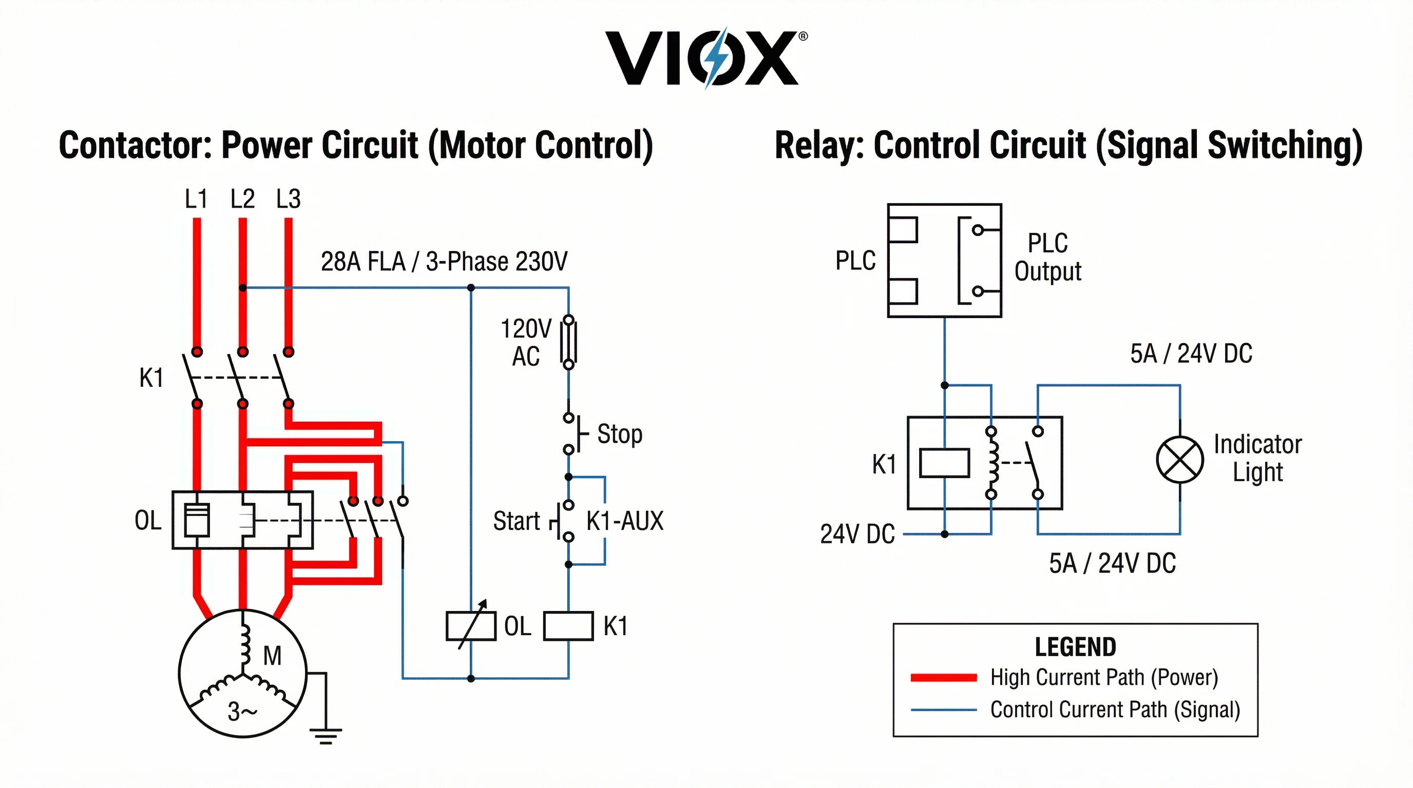
Contactor sizing follows NEC 430.83: the device must handle locked-rotor current per NEC Table 430.251(B). For a 10 HP, 230V three-phase motor (FLA 28A), select a contactor rated for at least 35A continuous with appropriate inrush capability.
HVAC Power Circuits
Commercial and industrial HVAC systems use contactors to switch compressors, condensers, and electric heating elements. These loads draw high inrush currents and require devices with AC-3 duty rating per IEC 60947-4-1.
- Rooftop units: compressor contactors rated 30-90A
- Chiller systems: multiple contactors for sequenced starting
- Electric heaters: resistive loads with high steady-state current
High-Capacity Lighting
Industrial facilities, parking lots, and sports venues use contactors for centralized lighting control. While individual circuits may be under 20A, simultaneous switching of multiple circuits requires contactor robustness.
When to Use Relays
Control Circuit Switching
Relays form the backbone of industrial control logic. They interface between PLCs, sensors, and controlled devices, providing electrical isolation and logic functions.
- Safety interlocks: emergency stop circuits, guard monitoring
- Sequence control: step-by-step process automation
- Alarm systems: fault annunciation and event logging
- PLC I/O expansion: discrete input/output modules
Control circuits typically operate at 24V DC or 120V AC. Relay coils match control voltage while contacts switch the load circuit—achieving electrical isolation between control and power domains.
Signal and Data Switching
Relays handle low-current signals in instrumentation, telecommunications, and test equipment. Their fast switching and clean contact closure make them ideal for precise timing and routing applications.
- Audio/video routing: studio switching matrices
- Test equipment: automated measurement systems
- Building automation: thermostat interfaces, lighting controls
- Automotive systems: fuel pumps, starter motors, accessory control
Pilot Duty Applications
Relays often control contactor coils, creating a control hierarchy. A small 24V DC relay operated by a PLC switches 120V AC power to a contactor coil, which then switches the three-phase motor. This cascading control provides isolation, reduces control wiring costs, and enables remote operation.
Selection Criteria: How to Choose
Step 1: Calculate Load Current
Determine the steady-state current and inrush current of your load. For motors, use nameplate FLA (full-load amperes) and calculate locked-rotor current from NEC Table 430.251(B).
For resistive loads like heaters, inrush equals steady-state. For capacitive loads (power supplies, LED drivers), measure or request inrush specifications from the manufacturer.
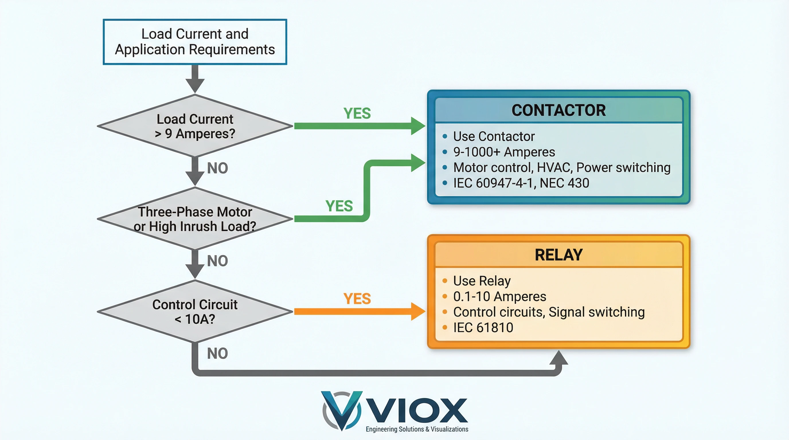
Rule of thumb: If steady-state current exceeds 9-10 amperes or inrush current is substantial, use a contactor.
Step 2: Match Voltage and Phase
Verify system voltage and phase configuration. Three-phase motor circuits require three-pole contactors. Single-phase loads may use contactors or heavy-duty relays depending on current.
For DC circuits, note that DC arcs are harder to extinguish than AC arcs. Use devices specifically rated for DC operation with appropriate voltage ratings.
Step 3: Assess Duty Cycle and Switching Frequency
- AC-3: Normal motor duty (starting, running, stopping)
- AC-4: Heavy motor duty (plugging, jogging, inching)
Relays have mechanical and electrical life specifications. A relay rated for 10 million operations at 5A may only achieve 100,000 operations at its maximum rated current.
Step 4: Consider Control Interface
Select coil voltage matching your control system. Common options: 24V DC (PLC control), 120V AC (pilot duty), 24V AC (HVAC control).
Determine if auxiliary contacts are needed for status feedback, interlocking, or downstream control. Contactors typically include or support add-on auxiliary contact blocks.
Quick Selection Guide
| Load Current | Application Type | Device Selection | Key Standard |
|---|---|---|---|
| < 5A | Control circuits | General-purpose relay | IEC 61810 |
| 5-9A | Light power switching | Power relay or small contactor | UL 508 |
| 9-30A | Single/three-phase motors | Contactor (AC-3 rated) | NEC 430, IEC 60947-4-1 |
| 30-100A | Industrial motors, HVAC | Standard contactor | NEC 430.83 |
| > 100A | Heavy industrial | Heavy-duty contactor | IEC 60947-4-1 |
Installation and Safety Requirements
Motor Circuit Protection (NEC Article 430)
Overload Protection
- 125% of motor FLA for motors with service factor ≥1.15 or 40°C temperature rise
- 115% of motor FLA for all other motors
Overload relays are often integrated with contactors in motor starter assemblies. For a 28A FLA motor with 1.15 service factor, set overload trip at 35A maximum (28A × 1.25).
Branch-Circuit Protection
- Inverse time breaker: 28A × 2.5 = 70A maximum
- Instantaneous trip breaker: 28A × 8 = 224A maximum
- Time-delay fuse: 28A × 1.75 = 49A maximum
Conductor Sizing
NEC 430.22 requires conductors sized at minimum 125% of motor FLA. For the 28A motor: 28A × 1.25 = 35A minimum ampacity. Select conductors from NEC Tables 310.16 or 310.17 based on installation conditions.
Control Circuit Installation
- Proper wire sizing: Match control circuit current and temperature rating
- Inductive load suppression: Flyback diodes for DC coils, RC snubbers for AC loads
- Clear documentation: Label contact forms (NO/NC) and terminal numbers per schematics
- Overcurrent protection: Fuse or breaker per NEC 725 for Class 1 control circuits
Troubleshooting Quick Guide
- Verify coil voltage with multimeter under load
- Check control circuit continuity and protective devices
- Inspect for mechanical obstructions or worn linkage
- Test coil resistance (typically 10-1000 ohms depending on rating)
- Measure load current; verify it’s within contactor rating
- Check for excessive inrush or short-circuit conditions
- Inspect arc chute condition and contact alignment
- Upgrade to higher-rated device with appropriate AC-3/AC-4 category
- Assess load current versus contact rating
- Add suppression for inductive loads (diodes, snubbers)
- Replace with sealed relay for contaminated environments
- Verify switching frequency doesn’t exceed rated electrical life
Frequently Asked Questions
What makes contactors safer for high-power applications?
Contactors incorporate arc chutes that divide, cool, and extinguish electrical arcs formed when interrupting high-current circuits. This built-in arc suppression, combined with robust contact materials and mechanical construction, enables safe repeated switching of motors and other high-energy loads that would destroy standard relays.
Can a relay replace a contactor for motor control?
No. Using a relay for motor main circuit switching is dangerous and violates NEC Article 430. Motor starting currents (6-8× running current) will weld relay contacts, creating a fire hazard. Relays lack the arc suppression, contact mass, and current capacity required for motor circuits. Use contactors rated per NEC 430.83 for motor applications.
How do I size a contactor for a three-phase motor?
Use motor nameplate FLA and NEC tables. Select a contactor rated for at least 125% of motor FLA with appropriate AC-3 duty rating per IEC 60947-4-1. Verify the contactor can handle locked-rotor current per NEC Table 430.251(B). For a 50 HP, 460V motor (65A FLA), choose a contactor rated minimum 81A continuous (65A × 1.25).
When should I use auxiliary contacts?
- PLC status monitoring (contactor closed/open indication)
- Safety interlocks (prevent multiple contactors closing simultaneously)
- Sequential control (contactor A must close before contactor B energizes)
- Alarm circuits (notify operators of unexpected contactor states)
Conclusion
Choose contactors for high-current power switching above 9 amperes, especially three-phase motors, HVAC compressors, and industrial loads requiring frequent switching with arc suppression. Choose relays for control circuits under 10 amperes where precision, speed, flexible contact forms, and compact size are priorities.
Proper selection ensures electrical safety, code compliance per NEC Article 430, and reliable system operation. Always coordinate device ratings with load characteristics, duty cycle, and protective devices. When in doubt, consult NEC tables, equipment datasheets, and consider professional engineering review for critical applications.
VIOX Electric manufactures industrial-grade contactors and relays for B2B applications. Our engineering team provides application support for motor control, HVAC, and automation systems. Contact us for device selection assistance and technical specifications tailored to your project requirements.
Related Resources
Single-Phase vs Three-Phase Relays
