On this page
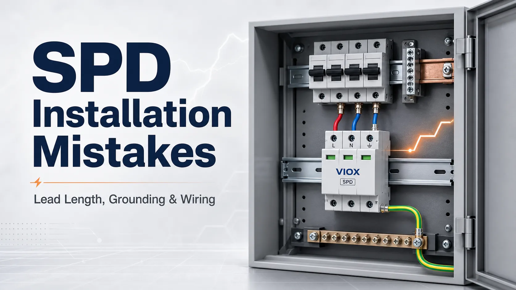
A surge protective device (SPD) can be correctly selected on paper and still perform poorly in the field if it is installed with long conductors, poor grounding, the wrong wiring configuration, or no visible way to confirm its status.
The most common SPD installation mistakes are excessive lead length, incorrect Type 1/Type 2 placement, poor bonding, wrong neutral/ground connections, missing backup overcurrent protection, and ignoring the status indicator. Longer SPD leads increase inductance, which raises let-through voltage and reduces the real protection level delivered to downstream equipment. In IEC-based low-voltage installations, IEC 60364-5-534 gives the well-known 0.5 m rule: the total SPD connecting conductor length should be kept as short as possible and should not exceed 0.5 m where practical.
If the installation is in North America, check the adopted edition of the National Electrical Code (NEC). Older references often cite NEC Article 285 for SPDs, while newer NEC editions organize overvoltage protection under Article 242. In IEC-based projects, SPD selection and installation are normally reviewed with IEC 61643 series guidance and the manufacturer’s installation instructions.
For product selection, see VIOX SPD for AC, DC, and solar systems. For type selection, use this companion guide: SPD Type 1 vs Type 2 vs Type 3.
Key Takeaways
- Longer SPD lead length increases inductance. During a fast surge, the extra voltage follows the physics behind
V = L x di/dt: more inductance and a faster current rise mean more voltage at the protected equipment. - IEC 60364-5-534 is a useful benchmark. In many IEC projects, the total SPD connection path from the live conductor to the SPD and from the SPD to the protective conductor should be kept within 0.5 m where possible.
- Physical connection quality matters as much as the SPD rating. A high kA rating cannot compensate for long loops, poor bonding, or incorrect terminals.
- Type 1 and Type 2 SPDs are not interchangeable by location. Type 1 devices may be used at service-side positions where permitted; Type 2 devices are normally installed on the load side of the service disconnect or overcurrent device.
- Every SPD needs a practical inspection method. A visual status window, mechanical flag, or remote signal contact helps maintenance teams know whether protection is still active.
- Manufacturer instructions control the final installation. Conductor size, backup fuse or breaker, terminal torque, wiring mode, and replacement module details must match the SPD documentation.
Quick Reference: Common SPD Installation Errors
| Mistake | Why It Matters | Field Check | Corrective Action |
|---|---|---|---|
| Long SPD conductors | Adds inductance and increases let-through voltage | Measure total lead length and look for loops | Mount SPD closer and route conductors short and straight |
| Wrong SPD type | Type 1, Type 2, and Type 3 have different installation roles | Confirm service entrance, distribution board, or point-of-use location | Match SPD type to installation point and standard requirements |
| Poor grounding or bonding | Surge current needs a low-impedance return path | Inspect bonding path, conductor routing, and terminations | Improve bonding, shorten path, follow grounding instructions |
| Incorrect wiring configuration | Wrong L/N/PE or system mode can make the SPD ineffective or unsafe | Compare installed wiring against the SPD diagram | Rewire according to system type and manufacturer diagram |
| No backup protection | Some SPD designs require upstream fuse or breaker coordination | Check SPD manual and panel drawing | Install specified backup fuse or breaker if required |
| Ignored status indication | A failed SPD can remain installed but provide no protection | Check visual flag/LED/remote alarm | Replace failed cartridge or complete SPD module |
| Poor lead routing | Loops and separated conductors increase surge impedance | Look for large conductor loops and separated paths | Route phase, neutral, and PE conductors together where applicable |
| Wrong voltage or MCOV/Uc | SPD may age prematurely or fail to clamp effectively | Compare system voltage with SPD label | Select SPD voltage rating for the real system |
| Outdoor enclosure mismatch | Moisture and temperature stress shorten device life | Check IP/NEMA rating and cabinet environment | Use suitable enclosure and condensation control |
| No commissioning record | Future inspection becomes guesswork | Check as-built drawings and labels | Record SPD type, location, status, and backup device |
1. Excessive SPD Lead Length
SPD conductors should be as short and direct as practical. The problem is not visual neatness; it is surge physics. A lightning or switching transient has a very steep current rise. Even a short wire behaves like an inductor at that frequency.
The additional voltage is governed by:
V = L x di/dt
Where V is the voltage added by the connection path, L is conductor inductance, and di/dt is the surge current rise rate. This is why a few extra centimeters of conductor can matter far more during a surge than it would during normal 50/60 Hz operation.
IEC 60364-5-534 gives a practical installation benchmark: the total connection length should be kept as short as possible and, where practical, should not exceed 0.5 m. In simplified form, this is often described as:
a + b <= 0.5 m
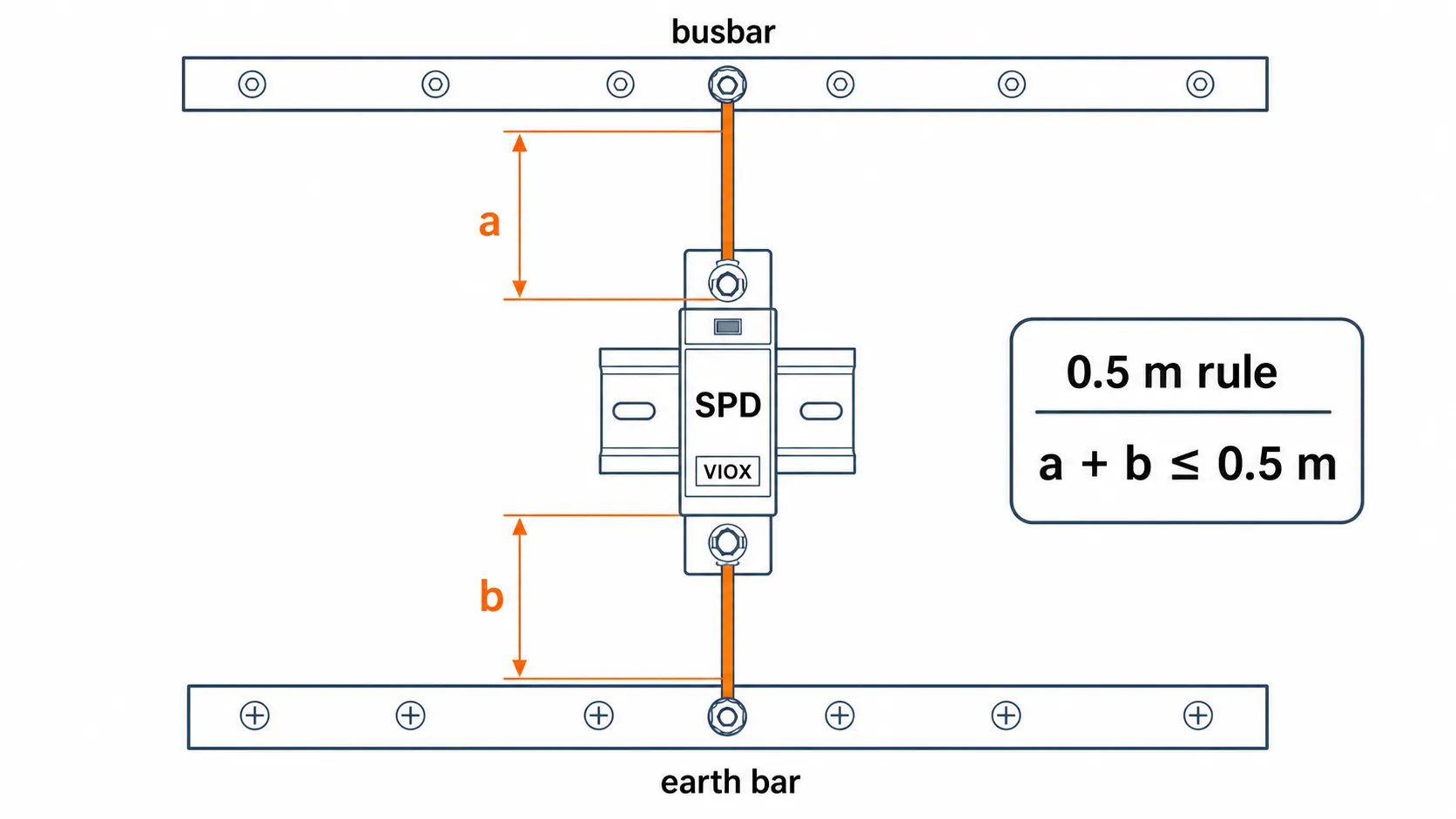
Where a is the conductor length from the live conductor or busbar to the SPD, and b is the conductor length from the SPD to the protective earth bar. If the installation cannot meet 0.5 m because of enclosure layout, the design should use better routing, a different SPD position, or a wiring method that reduces effective lead length.
During a surge event, excessive inductance creates additional voltage drop. The SPD may still operate, but the protected equipment sees a higher residual voltage than expected. This is why two installations using the same SPD model can perform very differently.
Good installation practice:
- Mount the SPD close to the busbar, main terminals, or protected circuit.
- Keep phase, neutral, and protective earth conductors short.
- Avoid decorative loops and unnecessary service coils.
- Route conductors together instead of separating them across the cabinet.
- Avoid sharp bends. A practical cabinet-building rule is to avoid tight 90-degree corners and keep bends smooth; where no manufacturer value is given, many installers use a minimum bend radius around 10 times the conductor outside diameter as a conservative workmanship target.
- Consider V-wiring when the panel layout and SPD terminal design allow it.
In failed inspections, the problem is often visible before any test instrument is used: the SPD is mounted neatly on a DIN rail, but its conductors travel around trunking, cross the cabinet, and return to the earth bar like a loop antenna.
2. Poor Lead Routing: Loops, Separation, and Inductive Paths
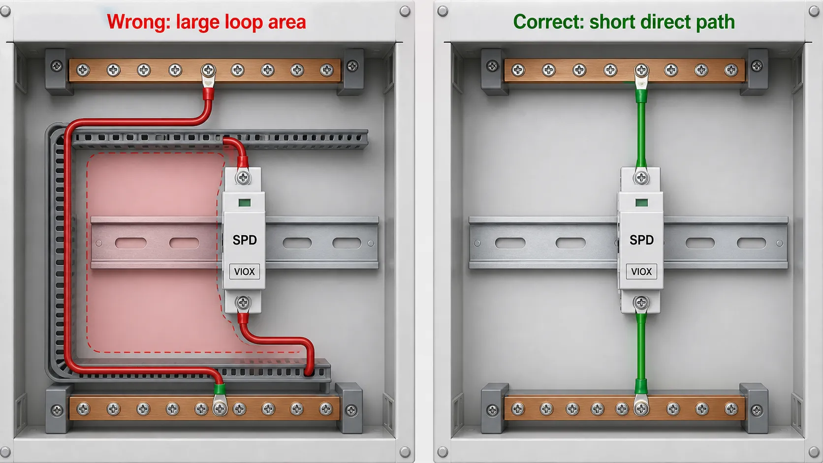
Lead length is only one part of the problem. Routing also matters. Long parallel loops increase loop area, and a larger loop area can increase inductive coupling during a fast transient.
In industrial panels, a common mistake is mounting the SPD on a clean DIN rail position far away from the real connection point because it makes the layout look balanced. The layout looks tidy, but the surge path becomes electrically worse.
Better routing approach:
| Routing Detail | Poor Practice | Better Practice |
|---|---|---|
| Conductor length | Long path around ducting | Short direct path to connection point |
| Conductor loop | Large loop for neat cable dressing | Compact route with minimum loop area |
| Phase and PE routing | Routed on opposite sides of cabinet | Routed close together where permitted |
| Crossing control wiring | SPD leads mixed through PLC wiring | Separate surge path from sensitive signal wiring |
| Bend style | Tight repeated bends | Smooth, direct bends |
V-Wiring and Kelvin-Style SPD Connections
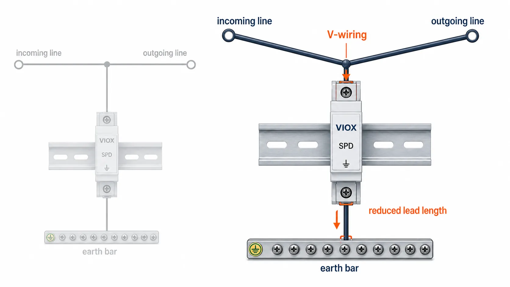
For some SPDs and panel layouts, V-wiring can reduce effective connection length. Instead of connecting the SPD with a long parallel tap from the main conductor, the incoming and outgoing conductor path is arranged so the SPD sits directly at the connection point. This is sometimes compared with a Kelvin-style connection because the protected circuit is referenced closer to the SPD terminals rather than at the end of a long branch lead.
This method is not universal. It depends on SPD terminal design, conductor size, current path, and the manufacturer’s wiring diagram. But for high-value panels, it is worth considering because it attacks the real problem: the voltage added by the connecting conductors. A useful drawing for this section is a three-part comparison: wrong loop wiring, short direct wiring, and V-wiring.
3. Wrong Type 1, Type 2, or Type 3 SPD Location
SPD types describe installation roles, not quality levels.
| SPD Type | Typical Installation Role | Common Mistake |
|---|---|---|
| Type 1 SPD | Service entrance or upstream side where permitted by code and listing | Using Type 2 where Type 1 is required for the location |
| Type 2 SPD | Load side of service equipment, distribution boards, subpanels | Installing on the line side of service overcurrent protection |
| Type 3 SPD | Point-of-use protection near sensitive equipment | Treating plug-in protection as a substitute for panel-level SPD |
| Type 1+2 SPD | Combined role where the device is rated and installed for both functions | Assuming every combined SPD fits every system grounding arrangement |
For North American installations, Type 1 SPDs are commonly evaluated for service-side or load-side use depending on listing and installation instructions, while Type 2 SPDs are normally installed on the load side of the service disconnect or overcurrent device. Always verify against the adopted NEC edition, the SPD listing, and the manufacturer’s wiring diagram.
For IEC projects, also verify whether the building has an external lightning protection system, whether the panel is the main distribution point or a downstream board, and whether Type 1, Type 2, or Type 1+2 coordination is required.
4. Incorrect SPD Wiring Configuration
SPDs are usually connected in parallel with the protected circuit, often described as a shunt connection. That does not mean every SPD is wired the same way.
The wiring configuration must match the system:
- Single-phase line-to-neutral system
- Three-phase TN-S, TN-C-S, TT, or IT system
- Grounded-wye or delta service
- AC distribution board
- DC photovoltaic combiner box
- Battery or other DC distribution system
At grounded service entrances, many training questions refer to SPDs being wired in a parallel or shunt configuration. On site, the more important step is to match the SPD wiring mode to the system grounding arrangement and the manufacturer’s diagram.
Common wiring errors include:
- Reversing line and neutral terminals.
- Treating PE and N as interchangeable.
- Using an AC SPD in a DC circuit.
- Installing a DC SPD with the wrong polarity or voltage configuration.
- Omitting the neutral-to-earth protection module where the SPD design requires one.
- Applying a three-phase wiring diagram to a single-phase panel.
For solar and DC applications, use DC-rated SPDs and verify polarity, maximum continuous operating voltage, and string voltage. For product evaluation, see VIOX DC SPD options.
5. Weak Grounding and Bonding
An SPD does not “absorb” all surge energy inside the device. It provides a controlled path to divert transient current away from the protected equipment. If the grounding and bonding path is poor, the SPD cannot deliver its intended protection level.
The issue is impedance, not only resistance. A grounding path may look acceptable under low-frequency testing but still perform poorly during a fast surge if it is long, looped, poorly bonded, or routed through high-inductance paths.
Field checks:
- Is the protective earth conductor connected to the correct terminal?
- Is the grounding conductor routed short and direct?
- Are bonding jumpers installed where required?
- Are painted surfaces, loose lugs, or corroded points increasing impedance?
- Does the installation follow the SPD manufacturer’s grounding conductor instructions?
The grounding conductor must be installed according to the SPD manufacturer’s instructions and the applicable electrical code. Do not “improve” the diagram by adding long detours or sharing questionable bonding paths.
6. Missing or Incorrect Backup Fuse or Breaker
Many SPDs require upstream backup overcurrent protection. The requirement depends on the SPD design, its short-circuit current rating, internal disconnector, maximum backup fuse or breaker, and installation standard.
The mistake is assuming the main breaker automatically provides the correct backup protection. In some panels, that may not satisfy the SPD manufacturer’s requirement. In other cases, adding the wrong small breaker can cause nuisance tripping or reduce surge performance.
Check these items before energizing:
| Item | What to Verify |
|---|---|
| Maximum backup protection | Fuse or breaker value permitted by SPD datasheet |
| Short-circuit current rating | SPD SCCR must suit available fault current |
| Device type | gG fuse, MCB, MCCB, or other device as specified |
| Selectivity | Whether SPD backup protection trips before upstream service interruption |
| Disconnector status | Internal or external disconnector condition after surge events |
Do not select backup protection by habit. Use the SPD manual, panel short-circuit study, and local code requirements.
7. Ignoring SPD Status Indicators
An SPD shall provide a practical way to indicate whether it is still functioning. Depending on the model, this may be a visual indicator, mechanical flag, LED, replaceable cartridge window, or remote signal contact.
The field problem is simple: a failed SPD can remain physically installed while no longer providing protection. In many control panels, the SPD is mounted at the bottom of the enclosure or behind wiring, so nobody checks it unless the maintenance plan specifically includes it.
Good maintenance practice:
- Make the status window visible after the panel door is opened.
- Use remote signaling contacts for critical panels or unmanned sites.
- Label the SPD location on the panel schedule.
- Record the SPD status during routine inspection.
- Replace failed modules with the correct manufacturer-approved cartridge.
If the indicator shows failure, do not reset and ignore it. Treat the SPD as a consumed protection component and replace the failed module or complete device as instructed.
8. Wrong Voltage Rating, Uc/MCOV, or System Type
Selecting by “kA rating” alone is a common sourcing mistake. The SPD must also match the system voltage and maximum continuous operating voltage.
In IEC documentation, this is typically expressed as Uc. In North American documentation, buyers often see MCOV (maximum continuous operating voltage). If this value is too low for the real system, the SPD may age quickly or disconnect during normal operation. If it is too high, protection may be less effective than expected.
Verify before purchase:
- Nominal system voltage.
- Maximum operating voltage.
- Earthing system.
- AC or DC application.
- Pole configuration.
- Temporary overvoltage risk.
- Voltage protection level required by protected equipment.
For a deeper explanation of SPD voltage parameters, use VIOX’s guide to SPD Type 1 vs Type 2 vs Type 3 and the related SPD product datasheet.
9. Poor Environmental Protection
SPDs installed inside clean indoor panels have a different life than SPDs installed in outdoor distribution boxes, rooftop PV combiner boxes, coastal cabinets, or humid pump-control enclosures.
Environmental mistakes include:
- Using an indoor panel SPD in an outdoor cabinet without suitable enclosure protection.
- Ignoring condensation inside sealed outdoor boxes.
- Mounting SPDs close to heat-generating devices without spacing.
- Using products outside the manufacturer’s temperature and altitude range.
- Ignoring corrosion risk in coastal or chemical environments.
The SPD rating is only one part of the system. The enclosure, ventilation, cable glands, drainage path, and maintenance access all affect reliability.
Field example: in outdoor PV combiner boxes, SPD problems are often blamed on “bad surge quality” when the more ordinary cause is moisture and condensation. A DC SPD mounted in a sealed box with no condensation control, poor cable gland sealing, and long earth routing is exposed to both electrical and environmental stress. In those cases, replacing the SPD without correcting the enclosure and wiring layout only resets the failure clock.
10. No Commissioning Record or Panel Labeling
SPD installation is often treated as a small accessory task, so it is missing from the final panel documentation. That creates problems later when maintenance teams need to identify the device, check replacement cartridges, or confirm whether the correct SPD type was installed.
At commissioning, record:
- SPD brand and model.
- Type 1, Type 2, Type 1+2, or Type 3 classification.
- Voltage rating and Uc/MCOV.
- Backup fuse or breaker.
- Installation location.
- Grounding arrangement.
- Status indicator condition.
- Remote contact wiring, if used.
- Date of inspection or replacement.
This record is especially important for industrial control panels, commercial distribution boards, telecom sites, solar PV systems, and critical loads.
SPD Installation Checklist
Use this checklist before energizing a panel with SPD protection.
| Check | Pass/Fail Question |
|---|---|
| SPD type | Does the SPD type match the installation point? |
| AC/DC rating | Is the SPD rated for the actual system type? |
| Voltage rating | Does Uc/MCOV match the real operating voltage? |
| Wiring configuration | Does wiring match the manufacturer’s diagram? |
| Lead length | Are conductors short, direct, and free from unnecessary loops? |
| Lead routing | Are SPD conductors routed together where applicable? |
| Grounding | Is PE/ground connected correctly and bonded properly? |
| Backup protection | Does the fuse or breaker match the SPD datasheet? |
| Status indication | Is the indicator visible or remotely monitored? |
| Enclosure environment | Does the cabinet suit moisture, dust, heat, and corrosion conditions? |
| Documentation | Are SPD details recorded in the panel file? |
When to Use Type 1+2 Instead of Separate Devices
Type 1+2 SPDs are useful where the installation needs both lightning-current capability and downstream surge limitation in one compact device. They are common in space-limited panels, solar PV applications, and sites where the main distribution point is exposed to higher surge risk.
However, a Type 1+2 label is not a shortcut around engineering checks. You still need to verify voltage, earthing system, short-circuit rating, backup protection, and manufacturer-approved wiring.
FAQ
What does longer SPD lead length increase?
Longer SPD lead length increases inductance. Higher inductance increases the voltage developed across the conductors during a surge, which reduces the effectiveness of the SPD and raises the voltage seen by protected equipment.
Are SPDs wired in series or parallel?
Most panel-mounted SPDs are connected in parallel, also called a shunt connection, with the protected circuit. The exact line, neutral, and protective earth wiring must follow the SPD manufacturer’s diagram and the system grounding arrangement.
What indication should an SPD provide?
An SPD should provide a way to show whether it is functioning properly. This may be a visual status window, LED, mechanical flag, replaceable cartridge indicator, or remote signaling contact depending on the model and application.
Can a Type 2 SPD be installed on the line side of the service disconnect?
In typical North American applications, Type 2 SPDs are installed on the load side of the service disconnect or overcurrent protection. Type 1 SPDs are the usual choice for line-side service positions where permitted by listing, code, and installation instructions.
What should the SPD grounding conductor follow?
The SPD grounding conductor should follow the manufacturer’s installation instructions and applicable electrical code. Keep the grounding path short, direct, correctly bonded, and free from unnecessary loops.
Why should SPD interconnecting leads avoid loops?
Loops increase the effective surge path impedance and can increase inductive voltage during a transient. Short, direct conductors routed close together generally improve SPD performance.
Does a green indicator always mean the whole system is protected?
No. A green indicator usually means the SPD module is still available, but it does not prove the installation has correct lead length, grounding, backup protection, or coordination. Visual status is one inspection item, not the whole commissioning test.
Should SPDs be inspected after a storm?
For critical equipment, yes. After nearby lightning activity, utility switching events, or repeated surge exposure, inspect the SPD status indicator and review any remote alarm. Replace failed modules according to the manufacturer’s instructions.
Is a plug-in surge strip enough for a building?
No. A plug-in surge strip can provide point-of-use protection for small electronics, but it does not replace service entrance or distribution-board SPD protection. Layered protection is normally more effective for panels, hardwired equipment, HVAC, control systems, and PV installations.
What is the safest way to choose an SPD for a panel?
Start with the system type, voltage, earthing system, installation point, available fault current, required SPD type, and manufacturer wiring diagram. Then verify backup protection, lead routing, enclosure environment, and inspection access.
VIOX Engineer’s Field Tip
When an SPD fails repeatedly, do not start by changing brands. Open the panel and trace the surge path with your finger: line conductor to SPD, SPD to earth bar, earth bar to bonding point. If that path is long, looped, separated, corroded, or hidden behind trunking, the SPD is being asked to do a job that the installation layout is undermining.
For panel builders, distributors, and EPC teams, the best SPD practice is to treat the device as part of the protection architecture rather than a late-stage accessory. Select the correct SPD, mount it close to the protected point, keep the connecting conductors short, follow the wiring diagram, and document the installation for future inspection.
For AC, DC, and solar SPD product evaluation, see VIOX surge protective device solutions.