On this page
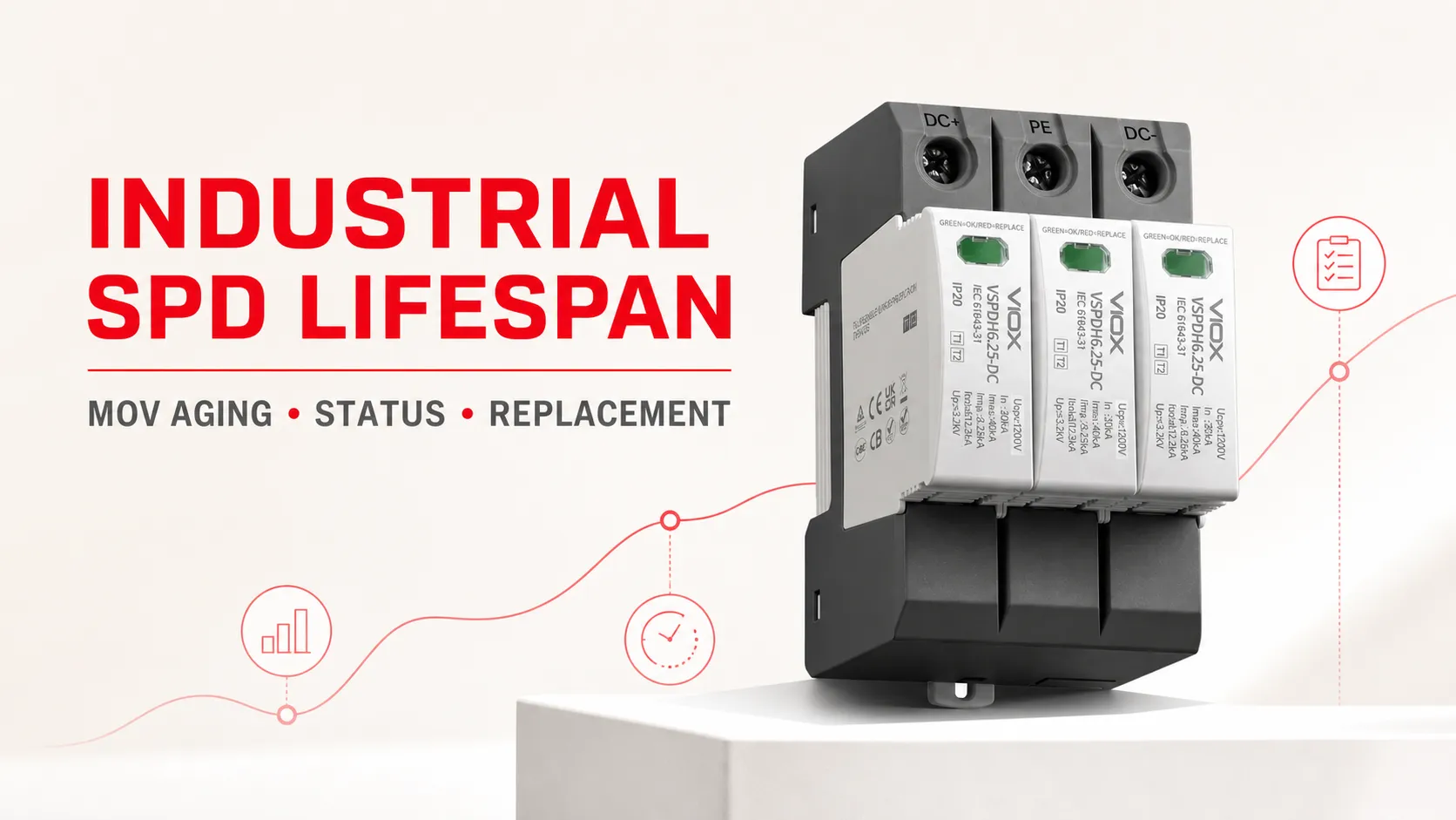
An industrial surge protective device (SPD) does not have a universal service life measured in years. Its condition depends on the electrical stress it has experienced, the suitability of its voltage and discharge ratings, temporary overvoltage (TOV) behavior, installation, environment, internal protective design, and the way its manufacturer indicates end of life.
Replace or service the affected SPD when its model-specific status indication or remote contact reports loss of protection, its internal disconnector has operated, or inspection finds heat, contamination, damaged terminals, a loose plug-in module, or other physical deterioration. Before installing another cartridge after an early or repeated failure, investigate the supply system, Uc or maximum continuous operating voltage (MCOV), TOV exposure, protection mode, backup protection, connections, and event history. Replacing the module without correcting the cause may only repeat the failure.
This guide covers DIN-rail and other industrial power SPDs. For the basic device and system boundary, start with what a surge protective device is. Plug-in power strips and residential replacement decisions belong in the separate guide to consumer surge-protector lifespan.
Key Takeaways
- Calendar age is not an end-of-life test. An SPD can remain serviceable for years in one installation or reach end of life after a severe event or abnormal system condition.
- A joule figure is not a countdown clock. Industrial SPD life cannot be calculated by subtracting estimated event energy from a “joule account.”
- Interpret indicators by the product documentation. Green, red, yellow, LEDs, mechanical flags, displays, and remote contacts are not universal remaining-life meters.
- A faulted module may be the symptom, not the root cause. Repeated failures require investigation of voltage selection, TOV, wiring, short-circuit coordination, environment, and application fit.
- Replaceable does not mean hot-swappable. Isolate and verify the equipment according to the manufacturer’s instructions and the site’s electrical-safety procedure before removing an SPD plug or assembly.
Industrial SPD Condition and Replacement Matrix
Only qualified personnel should inspect or service panel-mounted SPDs. The table is a decision aid; the product instructions, site procedure, and applicable local rules take priority.
| Observed condition | Safe verification | Likely interpretation | Recommended action |
|---|---|---|---|
| Model-defined end-of-life flag, fault LED, display message, or remote alarm | Confirm the indication in the exact model manual and identify the affected pole or protection mode | The internal disconnector or monitoring circuit may have declared that protection is no longer available | Treat the affected path as unprotected; replace the specified module or complete device as instructed |
| One plug-in module indicates failure while the base and adjacent modules appear normal | After safe isolation, inspect the plug, coding, base contacts, terminals, and corresponding conductor; review event records | A single protection mode may have reached end of life, or a local connection/system condition may have stressed it | Replace only the module if the manufacturer permits and the base is undamaged; investigate the affected mode |
| Multiple poles fail together or several SPDs alarm after one event | Correlate the time with lightning, switching, utility, generator, or network events; inspect upstream and downstream protection | A common high-energy event or system-wide abnormal voltage may have affected several modes or locations | Inspect the coordinated protection system before restoring confidence; replace all failed components identified by the procedure |
| A replacement module fails again unusually soon | Verify nominal voltage, actual steady-state voltage, Uc/MCOV, TOV conditions, earthing arrangement, topology, and product application | Misapplication, repeated TOV, wrong voltage selection, wiring error, environmental stress, or inadequate coordination is more likely than ordinary aging | Stop repeated like-for-like replacement until the root cause is identified and the specification is corrected |
| Indicator appears normal after a known severe event | Confirm what the indicator actually monitors; check event logs, enclosure condition, connections, and manufacturer post-event guidance | A normal binary indication may show that the disconnector has not operated; it does not necessarily quantify remaining surge capacity | Keep or replace according to the documented post-event process, criticality, and available diagnostics—not the color alone |
| Remote contact alarms but the local flag appears normal | Check the contact logic, auxiliary wiring, contact supply, BMS/PLC mapping, and manual | The alarm may represent an SPD fault, an auxiliary-circuit problem, or inverted NO/NC logic | Verify the signaling circuit before replacing the power module; do not ignore the alarm |
| Heat damage, odor, discoloration, cracked housing, contaminated terminals, corrosion, or loose contacts | De-energize under the site procedure and inspect the complete assembly and surrounding panel | The assembly may have suffered electrical, thermal, mechanical, or environmental damage beyond normal replaceable-element wear | Remove the affected assembly from service and replace damaged components; investigate the initiating condition |
| No local indication and no remote monitoring | Identify the model and its documented inspection or test method | Condition cannot be inferred from appearance or installation age alone | Use the manufacturer’s approved method; for critical assets, consider a maintainable SPD design with documented status monitoring |
Why an Industrial SPD Has No Fixed Expiration Date
An SPD spends most of its life connected to the power system while waiting for transient overvoltages. Its service history is therefore installation-specific. Two apparently identical devices can age differently because they do not see the same surge currents, TOVs, source impedance, protection modes, temperature, contamination, wiring impedance, or upstream coordination.
The International Electrotechnical Commission (IEC) does not turn these variables into a universal number of field years. IEC 61643-01:2024 defines common requirements, tests, ratings, and safety provisions for low-voltage SPDs. For AC power SPDs, IEC 61643-11:2025 supplements that common document and explicitly requires consideration of expected short-circuit conditions and TOV stresses when the source or application differs from its assumptions. These standards establish verified product behavior under defined tests; they do not predict the future disturbance history of one factory panel.
Use installation age as an asset-management field, not as the sole replacement threshold. The stronger decision inputs are condition indication, event history, electrical-system suitability, inspection findings, and manufacturer guidance.
Why the “Joule Account” Model Is Wrong for Industrial SPD Life
The old version of this page described the MOV as a fuel tank from which every surge subtracts a known number of joules. That analogy is too simple for an industrial SPD and can lead to false maintenance decisions.
Actual stress depends on the impulse waveform, peak current, duration, current sharing, protection mode, source impedance, repetitive-event pattern, thermal conditions, and the complete SPD design. One event and many smaller events with the same arithmetic energy total are not automatically equivalent. Nor can a facility normally know how much energy each internal component handled without a validated monitoring and product-specific lifetime model.
Industrial power SPDs are more usefully evaluated through their declared parameters and application context: SPD classification, Uc or MCOV, voltage protection level Up or VPR, nominal and maximum discharge ratings, impulse current where applicable, modes of protection, TOV behavior, short-circuit declaration, required backup protection, status indication, and installation instructions. The SPD datasheet guide explains how these declarations fit together.
How MOV Aging Can Lead to End of Life
Many voltage-limiting power SPDs use metal-oxide varistors (MOVs), although an SPD may use other nonlinear components or a coordinated combination. An MOV presents high impedance at normal system voltage and becomes conductive as voltage rises along its nonlinear voltage-current characteristic, diverting surge current and limiting the voltage at the protected side.
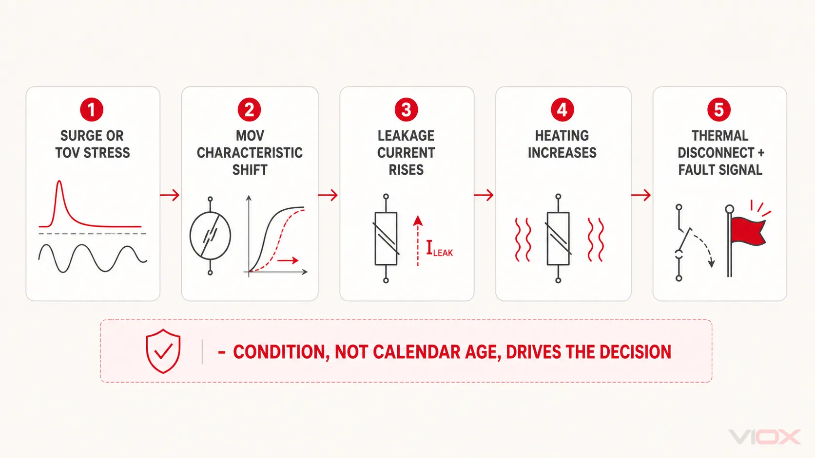
Electrical and thermal stress can alter that characteristic. In a common degradation path:
- Surge exposure or abnormal power-frequency voltage stresses the MOV.
- The MOV’s electrical characteristics change and leakage current at normal operating voltage can increase.
- Increased leakage produces additional heat.
- Heat can accelerate conduction and further heating.
- A correctly designed protective arrangement disconnects the stressed component before an unsafe thermal condition develops.
- The local indicator or remote signaling mechanism may then report that the affected protection path requires service.
Littelfuse technical guidance describes the same degradation-to-leakage-to-thermal-runaway chain and explains how a thermally protected varistor can disconnect from the source as it heats. This is a component-level mechanism, not proof that every complete SPD uses the same construction or indication. The ZnO MOV explainer covers the component physics in more depth, while the MOV, GDT, and TVS comparison explains why these technologies are not interchangeable in every protection stage.
Five Factors That Shorten Industrial SPD Service Life
1. Surge magnitude, waveform, repetition, and protection mode
A device is stressed by the current it actually conducts, not by a storm count on a calendar. External lightning effects, utility switching, capacitor-bank operations, load switching, and interactions within an installation can produce different waveforms and current paths.
Nominal discharge current In, maximum discharge current Imax, and impulse current Iimp are test-related declarations with different meanings. A larger printed kA number alone does not prove longer life in the installed system. Type, test class, installation point, exposure, voltage protection level, protection mode, and coordination must also fit the application.
2. Incorrect Uc or MCOV and TOV exposure
Uc in IEC terminology, or MCOV in common North American terminology, identifies the continuous voltage that can be applied to the SPD under specified conditions. Selecting it too close to the actual sustained operating voltage can expose the protection element to unwanted conduction and heating during voltage variation or abnormal system conditions.
Temporary power-frequency overvoltage is not simply another name for every long-term supply deviation. Its effect depends on magnitude, duration, earthing system, fault condition, equipment withstand, the SPD’s declared TOV behavior, and applicable installation rules. Review the complete system instead of assuming that a generic voltage protector solves every TOV condition. See MCOV and TOV and Uc versus Up for the voltage-selection boundary.
The NEMA Surge Protection Institute’s summary of IEEE C62.72 identifies repeated momentary or temporary overvoltages, sustained overvoltage, voltage misapplication, and installation errors among important end-of-life risks. That is why a prematurely faulted replacement module should trigger a system check, not an automatic assumption that a lightning surge “used it up.”
3. Wrong product boundary: AC, PV DC, and signal SPDs
Product category matters. IEC 61643-11:2025 addresses SPDs connected to AC low-voltage power systems, while IEC 61643-31:2018 addresses SPDs dedicated to the DC side of photovoltaic installations up to its stated scope. Signal and telecommunications SPDs use another application and standards framework.
Do not infer that a device suitable for one source, voltage, fault characteristic, or interface has the same end-of-life behavior in another. DC sources can sustain an arc differently from AC, PV arrays have application-specific voltage and fault behavior, and signal-line SPDs must preserve the electrical performance of the protected interface. Verify the exact intended circuit and standard on the datasheet.
4. Installation, conductor routing, and coordination
Incorrect connections, long or poorly routed conductors, unsuitable protection topology, inadequate bonding, wrong backup protection, loose terminals, and incorrect placement can reduce system protection or create abnormal stress. They can also make a healthy SPD appear ineffective because excessive connection voltage adds to the SPD’s residual voltage during discharge.
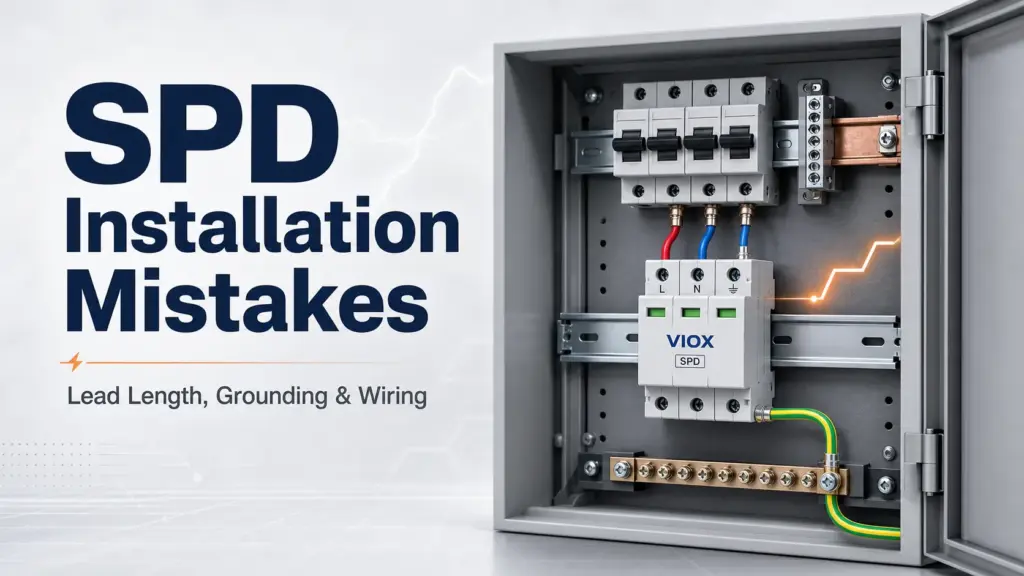
Detailed corrective wiring belongs in the SPD installation mistakes and correction guide. For lifecycle diagnosis, the key rule is to preserve evidence before replacement: photograph the indication and wiring, identify the failed mode, record protective-device status, and compare the installation with the exact product instructions.
5. Temperature, contamination, moisture, vibration, and enclosure conditions
The complete assembly includes more than the nonlinear protection element. Terminals, plug contacts, disconnectors, indication mechanisms, insulation, remote contacts, and the enclosure can all be affected by heat, dust, condensation, corrosive atmosphere, vibration, or mechanical damage.
Check the product’s environmental declarations and the panel’s actual conditions. A fault associated with corrosion, tracking, loose connections, or heat damage should not be treated as normal MOV wear resolved by changing only a cartridge.
What a Status Indicator Can—and Cannot—Tell You
Status indication is essential for maintainability, but it must be interpreted within the model’s documented design.
| Status function | What it can establish | What it normally cannot establish by itself |
|---|---|---|
| Mechanical local flag | The position of a mechanism linked to a monitored condition or disconnector, as defined by that model | Exact remaining surge capacity or the energy of past events |
| LED or electronic display | The model-defined operational, warning, or fault state while its monitoring circuit is functioning | A universal meaning based only on color |
| Floating remote changeover contact | A state change that can be sent to a PLC, building management system (BMS), or supervisory control and data acquisition (SCADA) input | The root cause of the state change unless additional diagnostics are provided |
| Event counter or intelligent monitoring system | Recorded events or a manufacturer-defined condition assessment, depending on design | A transferable remaining-life percentage for unrelated SPD models |
| No indication | Nothing beyond the absence of a visible status feature | Proof that protection remains available |
Phoenix Contact product documentation provides examples of replaceable protection plugs with green/red local indication and a remote signaling contact. DEHN documentation shows examples ranging from floating contacts and Modbus status reporting to model-specific three-stage condition indication. These examples demonstrate available maintenance architectures; they do not establish one universal color code or feature set for all industrial SPDs.
For BMS/SCADA logic, contact states, alarm wiring, and fail-safe monitoring, use the SPD remote-signaling guide and the exact contact diagram for the selected model.
What to Do When an Industrial SPD Reports End of Life
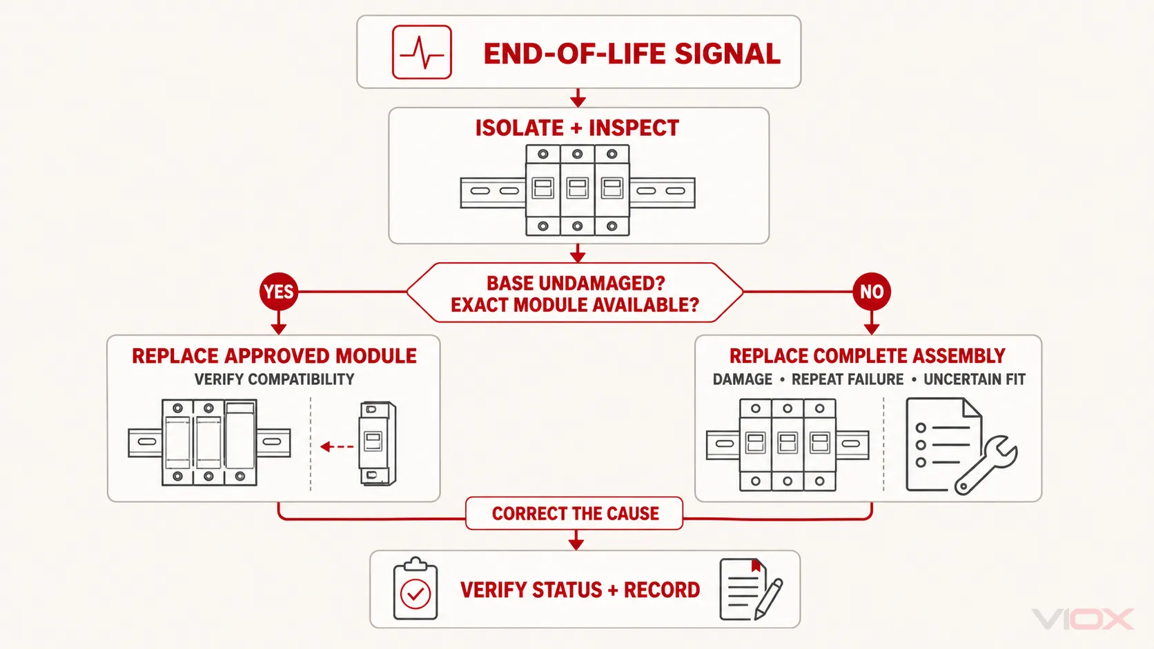
1. Treat the affected protection path as unavailable
An end-of-life indication is not a reset request. Apply the site’s risk controls for equipment that may now be operating without the intended surge-protection layer. Do not bypass an internal disconnector or force a plug back into service.
2. Make the panel safe under the approved procedure
SPD inspection and replacement expose workers to panel hazards. Qualified personnel should follow the site’s isolation, lockout/tagout, verification, personal-protective-equipment, and local electrical-safety requirements. A removable cartridge must not be assumed to be hot-swappable merely because it can be removed without rewiring the base.
3. Capture evidence before removing the device
Record:
- manufacturer, model, rating label, serial or batch information where available;
- installation location and protected equipment;
- failed pole, module, or protection mode;
- local indication and remote-alarm state;
- date, time, and any correlated lightning, switching, utility, generator, or process event;
- upstream protective-device condition;
- visible wiring, conductor routing, bonding, contamination, heat, and mechanical condition;
- installation and previous replacement dates.
This record separates a one-time event from a repeating application problem and improves the next procurement decision.
4. Check the likely cause before installing the replacement
Compare the actual system with the datasheet and installation instructions:
- nominal system voltage and actual operating voltage;
- Uc or MCOV for every relevant protection mode;
- earthing system and SPD topology;
- AC, general DC, PV DC, or signal-line application;
- SPD Type or test class and installation position;
- required backup protection and applicable short-circuit withstand/current declaration, such as SCCR or Isccr depending on the product and framework;
- terminal condition, conductor routing, and bonding;
- ambient and enclosure conditions;
- coordination with upstream and downstream SPDs.
5. Replace the correct scope and verify restoration
Use only a replacement plug or module identified by the manufacturer as compatible with the installed base. Confirm keying, ratings, protection technology, and contact function; similar appearance is not evidence of interchangeability.
After replacement and safe restoration, verify the model-defined local status and remote alarm logic. Update the asset record and retain the failed unit for examination when the failure was premature, repeated, physically abnormal, or associated with a significant event.
Replace the Module or the Complete SPD?
| Condition | Module replacement may be appropriate when… | Replace the base or complete assembly when… |
|---|---|---|
| End-of-life indication on one plug | The manufacturer permits plug replacement, the base is undamaged, and the replacement is an exact approved match | The model is non-modular, compatibility is uncertain, or the base also shows damage |
| Heat or arc evidence | Never assume a new plug alone resolves it | Contacts, terminals, insulation, base, or surrounding conductors show heat, tracking, deformation, or arcing |
| Corrosion or contamination | The condition is external, fully corrected, and all retained parts remain within manufacturer criteria | Moisture, contamination, or corrosion has entered or damaged the assembly |
| Repeated early failure | Only after the root cause has been identified and corrected | The assembly is misapplied, the base is suspect, or the retained design cannot meet the system requirement |
| Obsolete or unavailable cartridge | A manufacturer-approved current replacement exists | No verified compatible module is available or documentation cannot establish compatibility |
| Multi-pole or common event | Each affected plug and retained base pass the manufacturer’s inspection criteria | Multiple components, the common base, remote contacts, or insulation may have been compromised |
Build a Condition-Based SPD Maintenance Record
There is no responsible universal inspection interval for every facility. Set the review frequency through the manufacturer’s instructions, site electrical-maintenance program, asset criticality, environmental severity, lightning and switching exposure, and applicable local rules.
At minimum, the asset record should make these fields retrievable:
| Record field | Why it matters |
|---|---|
| Manufacturer, model, ratings, and applicable standard | Prevents incorrect replacement and preserves the original selection basis |
| Panel, circuit, protection mode, and protected load | Identifies the protection boundary and operational consequence of failure |
| Installation and replacement dates | Establishes history without treating age as proof of remaining life |
| Local and remote status at each review | Reveals state changes and signaling faults |
| Surge, lightning, switching, utility, and generator events | Helps correlate simultaneous or premature failures |
| Voltage-quality or TOV investigation results | Prevents repeated replacement caused by an unresolved system condition |
| Photographs and physical findings | Preserves evidence of wiring, contamination, heat, and mechanical condition |
| Replacement part and corrective action | Supports traceability and future root-cause analysis |
For critical sites, remote signaling can reduce the time between an SPD declaring a fault and maintenance becoming aware of it. It does not replace product-specific inspection, signaling-circuit verification, or investigation after an alarm.
Specify the Next SPD for Maintainability—not a Claimed Number of Years
When replacing or redesigning an industrial SPD installation, require evidence that matches the system:
- correct AC, DC, PV DC, or signal application;
- voltage rating and Uc/MCOV for the system and protection mode;
- suitable TOV declarations and application boundary;
- appropriate Type or test class, Up/VPR, In, Imax, and Iimp where applicable;
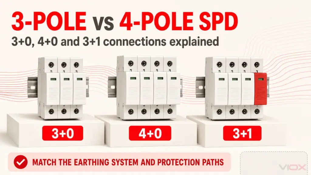
- compatible earthing-system topology and modes of protection;
- applicable short-circuit withstand/current declaration and backup-protection instructions;
- clear model-specific local status indication;
- remote signaling where operational criticality justifies it;
- documented compatible replacement modules and coding, if modular;
- environmental ratings suitable for the panel location;
- accessible datasheets, installation instructions, test/certification evidence, and replacement-part records.
Do not turn one large kA or joule number into a lifespan promise. A maintainable industrial SPD is one whose application is correct, failure state is observable, replacement scope is documented, and evidence can be checked during the life of the panel.
Frequently Asked Questions
How many years does an industrial SPD last?
No universal number applies. Service life depends on surge and TOV exposure, voltage selection, product design, installation, environment, and coordination. Use model-defined condition indication, inspection, event history, and manufacturer instructions rather than a generic year range.
Does a green SPD indicator prove the MOV is still at full capacity?
Not necessarily. It proves only the state defined for that model—often that a disconnector has not operated or that a monitored protection path remains available. It normally does not quantify original or remaining surge capacity. Check the manual.
Can a red SPD module be reset?
Usually an end-of-life indication associated with an operated internal disconnector requires replacement, not reset. Confirm the meaning and required action in the exact product instructions; do not bypass or repair a sealed protective module unless the manufacturer explicitly provides an authorized process.
Can an electrician test an SPD with a multimeter?
Visual inspection and continuity or auxiliary-contact checks may identify certain faults when permitted by the manufacturer, but an ordinary multimeter test does not reproduce standardized impulse performance or prove the remaining capability of a complete SPD. Use documented diagnostics and appropriately controlled test methods.
Should every module be replaced when one pole turns red?
Not automatically. The answer depends on the assembly design, the event, base condition, protection modes, manufacturer instructions, and site maintenance policy. Replace the indicated module only when the retained components pass the required inspection and the exact compatible cartridge is available. A common event, damage, or repeated failure can justify a wider replacement scope.
Why did the new SPD module fail again?
Repeated early failure points toward an unresolved application or system problem. Investigate Uc/MCOV, TOV, nominal and actual voltage, earthing topology, incorrect AC/DC/PV application, backup protection, wiring, environment, and coordinated protection before fitting another identical module.
Final Decision Rule
Do not replace an industrial SPD because an unsourced table says it has reached a certain birthday, and do not leave it in service solely because the panel is still powered or the device looks normal.
Use the manufacturer-defined status, physical condition, electrical-system fit, event history, and installation evidence to choose among four actions:
- Continue monitoring when status is normal, the application remains correct, and no damage or event-specific instruction requires action.
- Verify or investigate when indication is ambiguous, the remote signal conflicts with the local state, or a significant event occurred.
- Replace the approved module when the model declares end of life and the retained base and installation remain serviceable.
- Replace the complete assembly and correct the cause when there is heat, arcing, contamination, base damage, incompatibility, repeated early failure, or system misapplication.
To evaluate a replacement, review the VIOX SPD product family and request the exact datasheet, application standard, status-contact diagram, backup-protection instructions, replacement-module mapping, and certification evidence required for the intended system and market.
Sources Reviewed
- IEC 61643-01:2024 — Low-voltage surge protective devices, Part 01: General requirements and test methods
- IEC 61643-11:2025 — SPDs connected to AC low-voltage power systems
- IEC 61643-31:2018 — SPDs for photovoltaic installations
- NEMA Surge Protection Institute — How SPDs Work and End-of-Life Scenarios
- Littelfuse — LED Lighting Design Guide, MOV Selection and Thermal Protection
- Phoenix Contact — Example SPD with replaceable plugs, local status, and remote signaling
- DEHN — SPD Condition Monitoring and Remote Signaling