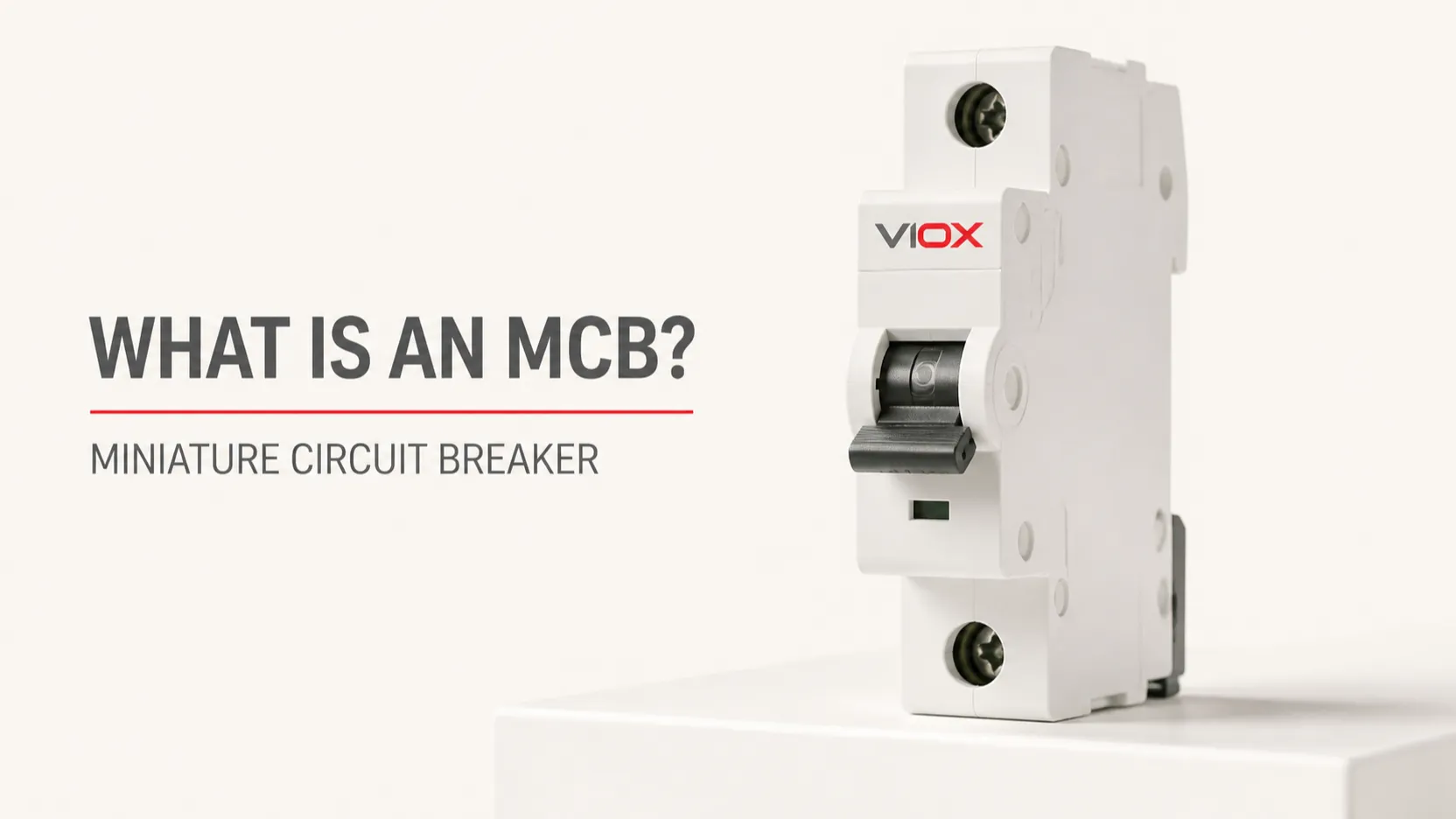
An MCB, or Miniature Circuit Breaker, is an automatic low-voltage protective device that opens a circuit when an overload or short circuit causes excessive current. It is selected primarily to protect circuit conductors and wiring and may also protect connected equipment when its characteristics are properly coordinated with the load.
Most MCBs used in distribution boards combine a time-delayed thermal trip for overload protection with an instantaneous magnetic release. The magnetic release responds rapidly when overcurrent reaches its pickup range, typically during a short circuit. After the fault has been found and cleared, the breaker can normally be reset instead of replaced.
This page explains the meaning, function, internal operation, and protection boundaries of an MCB. For model sizing and specification decisions, use the dedicated MCB Selection Guide.
MCB at a Glance
Question
Direct answer
What does MCB stand for?
Miniature Circuit Breaker
What does an MCB protect against?
Overload and short-circuit overcurrent
What is its primary protection objective?
Protecting circuit conductors and wiring from excessive current
How does it trip?
A thermal element responds to sustained overloads; a magnetic release responds rapidly when overcurrent reaches its instantaneous pickup range
Can it be reset?
Normally yes, after the fault has been cleared and the installation is safe to re-energize
Does it detect residual current?
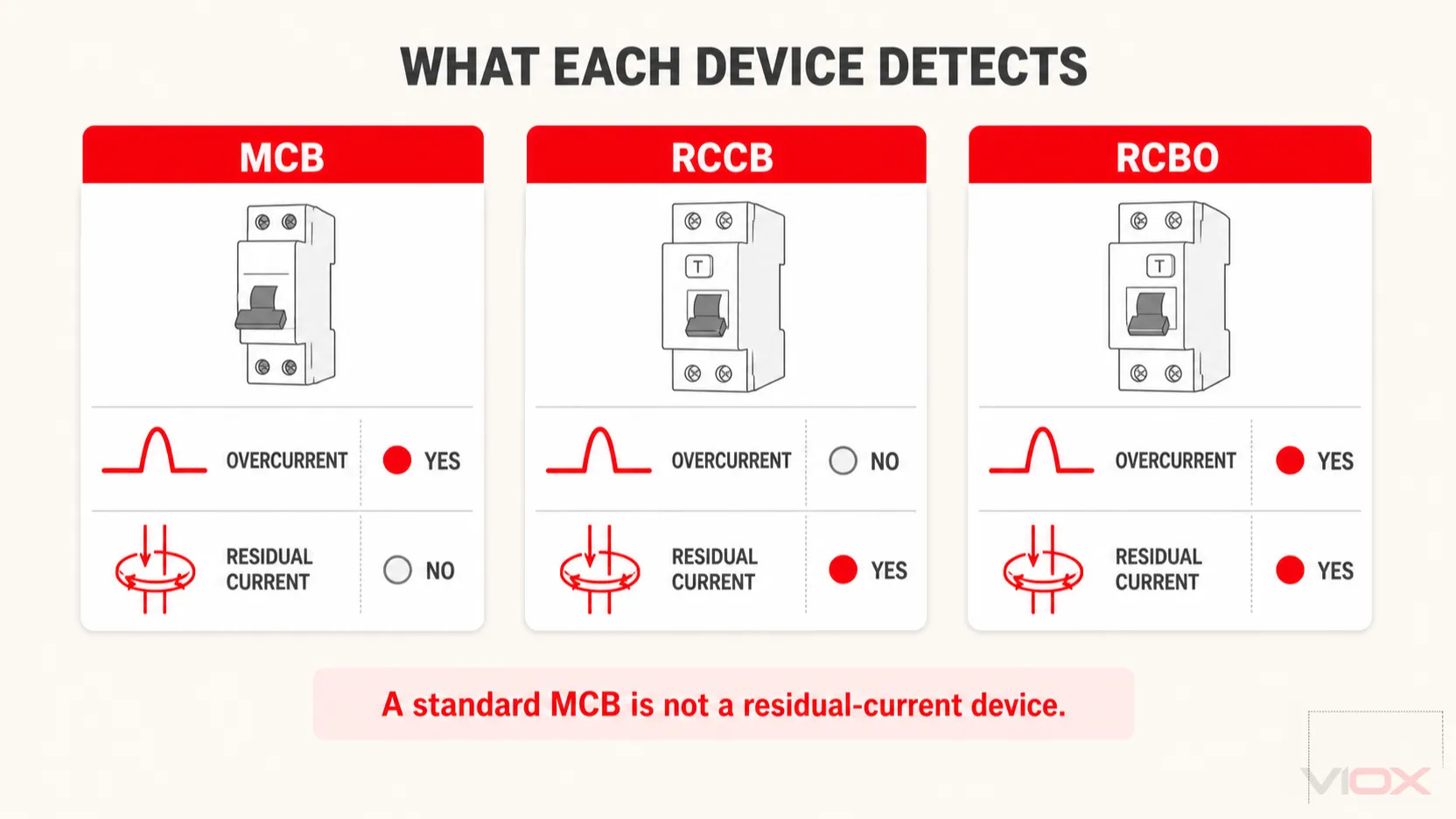
A standard MCB does not detect residual current and is not a substitute for an RCCB, RCD, or RCBO
Where is it used?
Final circuits, distribution boards, control circuits, and OEM equipment panels
What Does MCB Stand For?
MCB stands for Miniature Circuit Breaker.
“Miniature” describes its compact construction relative to larger breaker families; “breaker” describes its automatic interruption function. For an acronym-focused answer, see MCB Full Form in Electrical. This article focuses on function and operation.
What Does an MCB Protect Against?
An MCB responds to two forms of overcurrent:
Overload current: Current exceeds the circuit’s intended carrying capacity for long enough to create unacceptable heating.
Short-circuit current: A low-impedance fault typically produces a much larger current that reaches the instantaneous trip range and requires rapid interruption.
The MCB should be coordinated with conductor ampacity, installation conditions, load current, inrush current, available fault current, and any upstream or downstream protective device. Choosing a higher ampere rating is not automatically safer: a breaker that is too large may fail to protect the conductor as intended.
An MCB does not normally provide residual-current protection. It therefore must not be treated as a replacement for an RCCB, RCD, or RCBO where residual-current protection is required.
How Does an MCB Work?
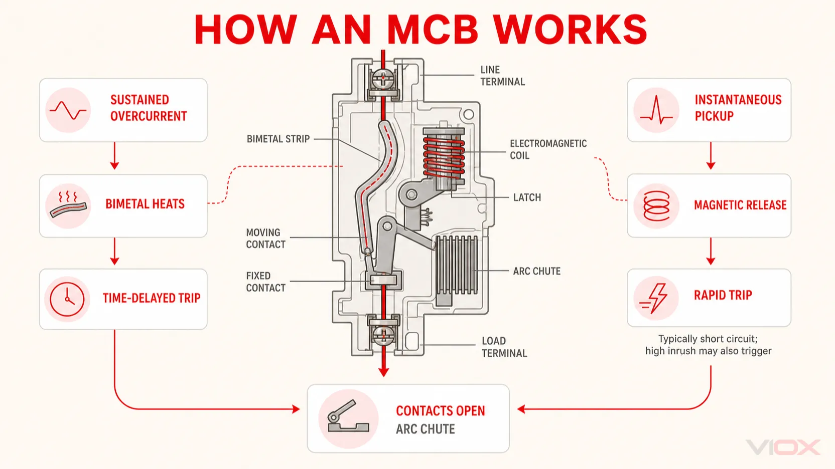
A typical thermal-magnetic MCB combines four actions:
The current passes through the internal current path and closed contacts.
A bimetal element responds to sustained overload current.
An electromagnetic release responds rapidly when overcurrent reaches its instantaneous pickup range.
When the contacts open, an arc chute divides, cools, and extinguishes the electrical arc within the breaker’s rated interruption capability.
Thermal overload trip
The thermal trip uses a bimetal strip. Current heats the strip, and a sustained overload causes it to bend until it releases the trip mechanism and opens the contacts.
This response is intentionally time-dependent. A modest overload generally takes longer to trip than a larger overload. The behavior helps the MCB tolerate short, non-damaging current peaks while limiting prolonged conductor heating.
Instantaneous magnetic release
The magnetic release uses an electromagnetic coil or solenoid. Normal current does not create enough magnetic force to operate the mechanism. When overcurrent reaches the instantaneous pickup range, the stronger magnetic field releases the latch rapidly. This usually occurs during a short circuit, but motor-starting or transformer-inrush current can also operate the release if it exceeds the threshold.
The instantaneous operating range is related to the trip characteristic. In IEC-style products, B, C, and D curves represent different magnetic pickup ranges; they are application characteristics, not quality grades.
Arc extinction
Opening contacts under fault current creates an arc. The arc chute draws the arc into metal splitter plates, where it is divided and cooled until current interruption is completed.
This is why an MCB is more than a manual switch. Its contact system, mechanism, insulation, and arc-control structure must operate together within the device’s declared voltage and breaking-capacity ratings.
Main Parts of a Miniature Circuit Breaker
Part
Function
Toggle handle
Provides manual ON/OFF operation and position indication
Operating mechanism
Opens the contacts manually or automatically and provides trip-free operation
Fixed and moving contacts
Carry normal current and separate during interruption
Bimetal strip
Provides time-delayed thermal overload tripping
Magnetic coil or solenoid
Provides rapid tripping when overcurrent reaches the instantaneous pickup range
Arc chute
Divides and cools the arc during interruption
Terminals
Connect approved conductors or compatible busbars
DIN-rail clip and housing
Support modular mounting, containment, and insulation
MCB Ratings and Markings
Two MCBs with the same ampere rating may behave differently. Read the complete marking set and the manufacturer’s technical documentation.
Marking
Application check
Rated current, In
Coordinate with design current, conductor ampacity, ambient conditions, and installation method
Rated voltage
Match the system voltage and current type; do not assume an AC rating also applies to DC
Trip characteristic
Match load inrush and available fault current
Breaking capacity
Verify it is adequate for the prospective short-circuit current at the installation point
Pole configuration
Match the wiring system and required disconnection arrangement
Product standard
Use the rating terminology and application scope of the declared standard
Terminal capacity
Follow the product instructions for conductor, busbar, preparation, and tightening
On many MCBs, 6kA or 10kA identifies a declared short-circuit breaking capacity under a specified product standard and test sequence. The exact symbol may be Icn, Icu, or Ics, depending on the applicable standard and device category, so the number must be interpreted together with the standard reference and manufacturer documentation.
A 10kA device is not automatically the correct choice for every circuit, and a 6kA device is not automatically adequate. The rating must be checked against the prospective short-circuit current and the protection arrangement. See MCB Breaking Capacity: 6kA vs 10kA for the dedicated selection discussion.
Standards Context: IEC 60898-1, IEC 60947-2, and UL 489
The word “MCB” is used across markets, but the application context and rating language are not identical.
Standard context
General scope relevant to this article
Practical implication
IEC 60898-1
AC circuit breakers for overcurrent protection in household and similar installations, within the standard’s voltage, current, and short-circuit-capacity limits
Common context for modular B, C, and D curve MCBs in final distribution
IEC 60947-2:2024
Circuit breakers for low-voltage switchgear and controlgear applications operated by instructed or skilled persons, within its stated voltage scope
Industrial application and rating terminology may differ from IEC 60898-1
UL 489
Molded-case circuit breakers, molded-case switches, and circuit-breaker enclosures for the relevant North American product context
Do not apply IEC curve markings or rating assumptions automatically to UL products
A standard reference printed on a device is not, by itself, proof that every version or model has a particular third-party certification. Verify the exact model documentation required for the target market.
Common MCB Types
Trip curves
Curve
Common instantaneous range in IEC 60898-1 applications
Typical load behavior
B
3–5 × In
Low inrush, including many resistive and lighting circuits
C
5–10 × In
Moderate inrush and mixed commercial loads
D
10–20 × In
Higher inrush, subject to adequate fault current and coordination
K or Z
Product- and manufacturer-dependent
Use only where the declared time-current curve matches the application
Protected phase plus switched neutral, subject to the specific product design
2P
Two mechanically linked poles; protection arrangement must be confirmed from product data
3P
Three-pole operation for three-phase circuits
3P+N
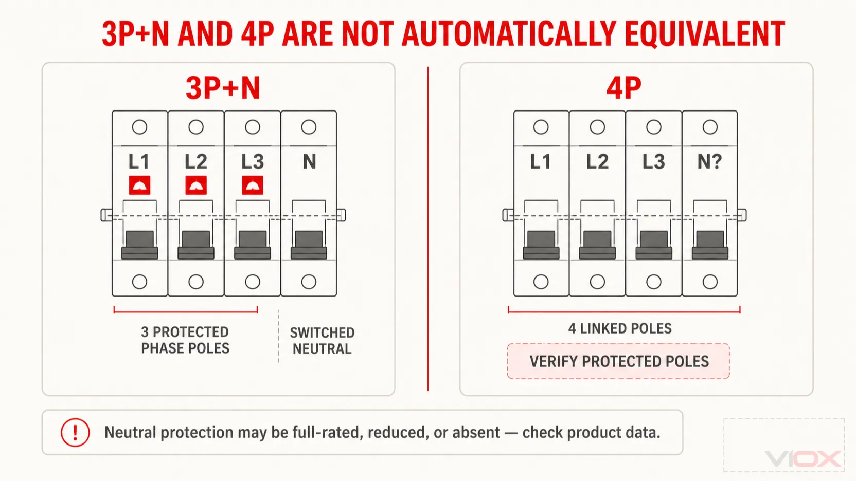
Three phase poles plus a mechanically linked neutral pole. The phase poles are generally protected; confirm whether the neutral pole is switched only and how it operates from the product documentation
4P
Four mechanically linked poles. Confirm how many poles include overcurrent releases and whether neutral protection is full-rated, reduced, or absent
Pole selection depends on the wiring system, earthing arrangement, local rules, product construction, and required isolation or disconnection function.
MCB vs Fuse, MCCB, RCCB, and RCBO
Device
Main protection function
Resettable?
Important boundary
MCB
Overload and short-circuit protection
Yes
Does not normally detect residual current
Fuse
Overcurrent protection using a replaceable element
No
Selection depends on utilization category, fault duty, and coordination objective
MCCB
Overcurrent protection over broader current, interruption, and adjustment ranges
Yes
Commonly used for feeders and larger distribution duties
RCCB / RCD
Residual-current protection
Usually yes
An RCCB without integral overcurrent protection still needs appropriate overcurrent protection
RCBO
Residual-current protection with integral overcurrent protection
Yes
Combines the relevant functions of an RCD/RCCB and an overcurrent protective device
In IEC terminology, RCCB may be expanded more precisely as Residual Current Operated Circuit-Breaker without Integral Overcurrent Protection. RCBO means Residual Current Operated Circuit-Breaker with Integral Overcurrent Protection.
residential final-distribution boards for lighting, socket, and dedicated appliance circuits;
commercial distribution panels and small branch circuits;
industrial control panels for control transformers, power supplies, PLC circuits, solenoids, and auxiliary circuits;
OEM machines that require compact, repeatable DIN-rail circuit protection; and
appropriately rated DC systems, including some solar, battery, telecom, and control applications.
DC use requires a specifically declared DC rating. Do not assume that an AC MCB can interrupt a DC circuit safely. Voltage, polarity, number of series poles, and breaking capability must follow the exact device instructions. For the separate DC topic, see the DC Circuit Breaker Guide.
What Must Be Checked Before Selecting an MCB?
This article explains the device rather than replacing an engineering selection process. At minimum, selection requires checking:
circuit design current and conductor ampacity;
system voltage and AC or DC application;
prospective short-circuit current;
declared breaking capacity under the applicable standard;
load inrush and time-current characteristic;
pole configuration and disconnection requirements;
ambient and enclosure conditions;
conductor, terminal, and busbar compatibility; and
coordination with upstream and downstream protection.
Use the MCB Selection Guide for the complete decision process. When the application requirements are known, the VIOX MCB product page provides the available product families for evaluation.
Frequently Asked Questions
What is the main function of an MCB?
The main function of an MCB is to interrupt overload and short-circuit overcurrent so that circuit conductors are protected within the intended design and coordination conditions.
How does an MCB work?
A typical MCB uses a thermal element for time-delayed overload tripping and a magnetic release that operates rapidly when overcurrent reaches its instantaneous pickup range, typically during a short circuit. High starting or inrush current can also operate the magnetic release if it exceeds that range. When the contacts open, an arc chute helps control and extinguish the arc.
Does an MCB protect against electric shock?
A standard MCB is not a residual-current device and does not provide additional protection based on residual current. It may disconnect some earth faults when the resulting overcurrent reaches its trip threshold, but it must not be treated as a substitute for an RCCB, RCD, or RCBO where residual-current protection is required.
What is the difference between an MCB and an RCBO?
An MCB provides overcurrent protection. An RCBO combines residual-current protection with integral overcurrent protection, allowing it to respond to the relevant leakage faults as well as overloads and short circuits.
What is the difference between an MCB and an MCCB?
An MCB is generally a compact modular breaker used for final and smaller branch circuits. An MCCB covers broader current, breaking-capacity, trip-unit, and accessory requirements and is commonly used for feeders and larger distribution duties. Exact application boundaries depend on the product standard and manufacturer range.
What does C16 mean on an MCB?
On an MCB using IEC-style B, C, or D curve markings, C16 normally identifies a C trip characteristic and a rated current of 16 A. The remaining markings must still be checked for voltage, breaking capacity, standard, pole arrangement, and application limits.
Does a higher ampere rating make an MCB safer?
No. The rating must coordinate with the conductor and circuit design. Increasing it without confirming conductor ampacity and protection requirements may leave the wiring inadequately protected.
Can an MCB be used as an ON/OFF switch?
An MCB can be operated manually, but it is primarily an overcurrent protective device. Its suitability for isolation, operational switching, switching frequency, and the specific load must be confirmed from the applicable standard and manufacturer documentation. A suitably rated switch or contactor may be more appropriate for routine control.
Conclusion
An MCB is a resettable circuit breaker that primarily protects circuit conductors against overload and short-circuit overcurrent. Its operation combines a thermal overload release, a magnetic short-circuit release, a trip mechanism, contacts, and an arc chute.
Correct application depends on more than the ampere number printed on the front. The circuit designer must also verify the voltage, trip characteristic, breaking capacity, poles, product standard, installation conditions, and coordination with residual-current and upstream protection.
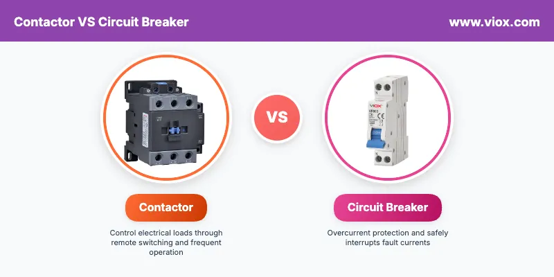
Quick Answer: A contactor is a control device built for frequent, remote-controlled load switching during normal operation. A circuit breaker is a protective device designed to detect and interrupt overcurrent caused by overloads or short circuits. In most industrial and commercial panels, contactors and circuit breakers work together — the contactor handles routine switching duty while the circuit breaker provides fault protection.
Why the Contactor vs Circuit Breaker Distinction Matters
If you are comparing a contactor and a circuit breaker, the first thing to understand is this: they are not competing components. They solve fundamentally different problems in an electrical system.
A contactor is a control device. A circuit breaker is a protective device. That single distinction drives every difference in design, rating, selection, and application that follows.
The confusion is understandable — both devices open and close circuits, both handle significant current, and both appear in the same motor control panels and distribution boards. But treating them as interchangeable creates weak points in your electrical system that show up as welded contacts, nuisance trips, premature device failure, poor fault discrimination, or — in worst cases — fire and equipment destruction.
This guide covers everything electrical engineers, panel builders, facility managers, and electricians need to know about the contactor vs circuit breaker comparison: how each device works, when to use which, why motor panels typically require both, and the most common misapplications that lead to expensive failures.
What Is a Contactor? Definition, Function, and Utilization Categories
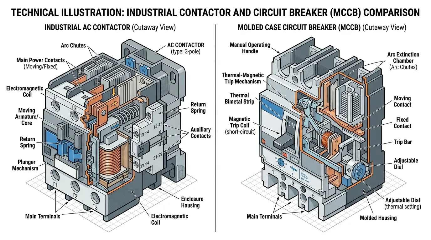
Technical Illustration: A side-by-side comparison revealing the internal engineering differences between an industrial AC contactor’s electromagnetic coil mechanism and a molded case circuit breaker’s (MCCB) thermal-magnetic trip unit.
A contactor is an electrically controlled switching device designed to make and break electrical circuits under normal load conditions. It uses an electromagnetic coil to pull in a set of main power contacts, allowing low-voltage control signals from PLCs, timers, or manual push buttons to switch high-power loads remotely and repeatedly.
Think of a contactor as a heavy-duty remote-controlled switch engineered for a life of constant use. To understand the internal components and design logic of an AC contactor, the key elements include the electromagnetic coil assembly, main power contacts, auxiliary contacts, arc chutes, and a spring return mechanism.
Core Contactor Characteristics
Electromagnetically operated — a control coil (typically 24V, 120V, or 240V AC/DC) drives the contact mechanism
High switching endurance — rated for hundreds of thousands to millions of operations
Remote control by design — intended to be commanded by external logic, not operated manually
Load-type sensitive — performance depends on the category of load being switched
No inherent overcurrent protection — a contactor does not trip on overload or short circuit by itself
Why Utilization Categories Matter
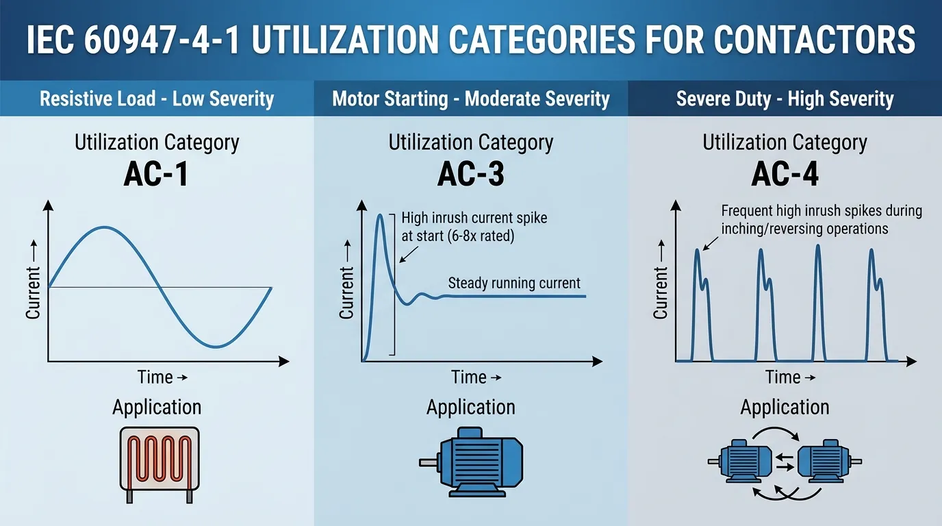
IEC 60947-4-1 Standards: Visualizing the switching severity and current waveforms across contactor utilization categories AC-1 (resistive), AC-3 (motor starting), and AC-4 (severe duty).
This is where many comparison articles fall short. A contactor’s real capability is not fully described by its current rating alone. The utilization category under IEC 60947-4-1 defines what kind of load the contactor is designed to switch and under what conditions:
Category
Load Type
Typical Application
Switching Severity
AC-1
Non-inductive or slightly inductive resistive loads
Heating elements, resistance furnaces, lighting
Low — current at make and break is near rated current
AC-3
Squirrel cage motors — starting, disconnecting during run
Pumps, fans, compressors, conveyors
Moderate — high inrush at make (6–8× rated), break at running current
Severe — high inrush at make AND high current at break
A contactor rated 95A under AC-1 might only be suitable for 60A under AC-3 and perhaps 40A under AC-4 — all for the same physical device. Ignoring utilization category is one of the most common specification errors in industrial panels.
Expert Tip: For motor control applications, always select contactors based on AC-3 (or AC-4 for severe duty) ratings, not the headline AC-1 current rating printed on the device label.
Common Contactor Applications
Motor control — starting, stopping, reversing, and speed-change switching for electric motors (often paired with motor starters)
HVAC systems — compressor control, fan motor switching, electric heating elements
Lighting control — large-scale commercial, street, and stadium lighting using modular contactors
Contactors also differ from relays, though the two are often confused. For a deeper comparison, see our guide on contactors vs relays.
What Is a Circuit Breaker? Protection Fundamentals and Trip Characteristics
A circuit breaker is an automatic switching device designed to protect electrical circuits from damage caused by overcurrent — whether from overload conditions or short circuits. Unlike a contactor, a circuit breaker’s primary job is not to switch loads on and off during normal operation. Its job is to sit quietly, carry current safely, and trip reliably when something goes wrong.
Automatic fault detection and tripping — thermal elements sense overload, magnetic elements sense short circuits
Manual reset after fault clearing — the device must be intentionally reset before re-energizing the circuit
Arc extinction technology — designed to safely extinguish the high-energy arcs that form when interrupting fault current
Defined interrupting capacity — rated to safely clear a specific maximum fault current (e.g., 10kA, 25kA, 65kA)
Infrequent operation — designed for thousands, not millions, of switching operations
Trip Characteristics Explained
Circuit breakers are selected not just by current rating but by their trip behavior, which determines how fast the device responds to different levels of overcurrent:
Trip Element
What It Detects
How It Works
Response Time
Thermal (overload)
Sustained overcurrent above rated current
Bimetallic strip heats and bends, releasing the trip mechanism
Seconds to minutes (inverse time — higher overcurrent = faster trip)
Magnetic (instantaneous)
High fault current from short circuits
Electromagnetic coil generates force to release trip mechanism
Milliseconds
Electronic
Programmable overcurrent thresholds
Microprocessor-based trip unit with adjustable settings
Configurable
The trip curve — often designated as B, C, or D for MCBs — defines the instantaneous magnetic trip threshold relative to rated current. A C-curve breaker trips instantaneously at 5–10× rated current, making it suitable for general loads with moderate inrush. A D-curve breaker tolerates up to 10–20× for high-inrush loads like motors and transformers.
Safety Warning: Never use a circuit breaker as a regular on/off switch. Circuit breakers are designed for infrequent operation. Frequent manual switching accelerates wear on the contact system and trip mechanism, compromising the device’s ability to protect during an actual fault. This is fundamentally different from a circuit breaker used as an isolator.
Contactor vs Circuit Breaker: Comprehensive Comparison Table
This enhanced comparison table covers every specification and functional difference engineers and panel builders need to evaluate:
Criteria
Contactor
Circuit Breaker
Primary Role
Frequent load switching and remote control
Overcurrent protection and fault interruption
Operating Principle
Electromagnetic coil drives contact closure; spring returns contacts to open position
Thermal-magnetic or electronic trip unit detects overcurrent and releases latch mechanism
Normal Operating Duty
High frequency — daily, hourly, or per-minute switching cycles
Infrequent — operates only during faults or manual maintenance isolation
Fault Interruption
Not designed as a primary fault-clearing device
Core function — designed to safely interrupt overload and short-circuit current
Switching Endurance
100,000 to 10,000,000+ operations (mechanical); 100,000 to 2,000,000 (electrical at rated load)
10,000 to 25,000 operations (mechanical); 1,500 to 10,000 (electrical)
Current Ratings
9A to 800A+ (power contactor range)
0.5A to 6,300A+ (MCB through ACB range)
Voltage Ratings
Up to 1,000V AC / 750V DC
Up to 1,000V AC (LV); higher for MV/HV breakers
Interrupting Capacity
Limited — typically 1–10× rated current for short durations
High — 6kA to 200kA+ depending on breaker type
Trip Characteristics
None — no inherent overload or short-circuit protection
Thermal, magnetic, electronic, or combination
Control Interface
Coil voltage input (24V, 48V, 110V, 230V, 400V AC/DC)
Manual handle + automatic trip; remote trip available on some models
Auxiliary Contacts
Typically included; NO and NC configurations for status and interlocking
Available as accessories on most MCCBs and ACBs
Arc Handling
Optimized for repeated make/break arcs during normal load switching
Optimized for high-energy arc extinction during fault interruption
Key IEC Standard
IEC 60947-4-1 (contactors and motor starters)
IEC 60947-2 (industrial) / IEC 60898-1 (household and similar)
Typical Installation
Motor starters, control panels, lighting panels, automation cabinets
Main panels, distribution boards, feeder circuits, motor branch protection
Cost Range
$15–$2,000+ (depending on size and category)
$5–$5,000+ (MCB through ACB range)
The Real Difference: Switching Duty vs Protection Duty
The contactor vs circuit breaker comparison ultimately comes down to a single engineering concept: duty.
Contactor Duty — Designed for the Grind of Daily Operation
A contactor expects to work hard every single day. In a pump station, it might cycle a motor on and off dozens of times per shift. In a commercial lighting system, it switches thousands of amperes of lighting load at sunrise and sunset. In an automated manufacturing line, it may operate hundreds of times per hour.
This relentless duty cycle shapes every aspect of the contactor’s design:
Contact materials are selected for low contact resistance and resistance to erosion from repeated arcing — typically silver alloys (AgCdO, AgSnO₂, AgNi)
Arc chutes are designed to quickly extinguish the moderate arcs that form during normal load switching
Coil and armature assemblies are optimized for millions of mechanical operations
Spring mechanisms maintain consistent contact pressure across the device’s entire life
A contactor rated for AC-3 duty at 95A might handle 2 million electrical switching operations at that current. The same device could handle 10 million mechanical operations with no electrical load. That endurance is the defining design priority.
Circuit Breaker Duty — Built to Wait, Then Act Decisively
A circuit breaker lives a fundamentally different life. It may sit in a panel for years, silently carrying current, and only operate a handful of times — ideally never under true fault conditions. But when a fault occurs, the breaker must interrupt potentially enormous current (tens of thousands of amperes) safely and reliably.
This protection-first duty shapes the breaker’s design differently:
Contact systems are engineered to withstand the thermal and mechanical stress of high fault-current interruption
Arc extinction systems (arc chutes, arc splitters, gas-blast chambers) handle orders of magnitude more energy than a contactor ever sees during normal switching
Trip mechanisms (bimetallic strips, magnetic coils, electronic trip units) provide calibrated response to overcurrent conditions
Mechanical latches hold contacts closed against spring pressure, enabling automatic release during faults
A typical MCCB might be rated for 10,000 mechanical operations — adequate for its intended duty, but roughly 1,000× fewer than a contactor. That tradeoff is by design, not a deficiency.
Arc Extinction: Where the Engineering Difference Becomes Visible
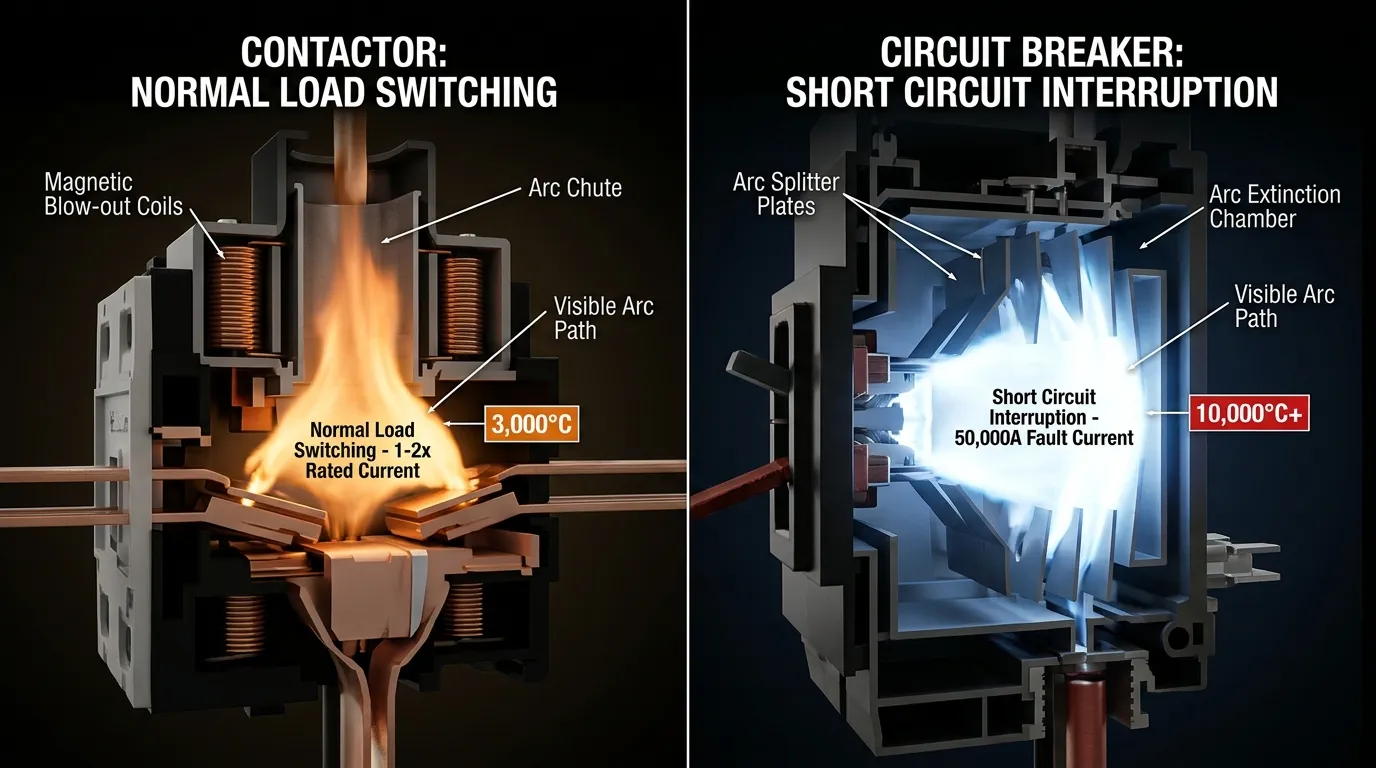
Thermodynamics in Action: A cross-sectional view highlighting how contactors manage repetitive, low-energy switching arcs (~3,000°C), whereas circuit breakers are built to survive explosive, high-energy fault interruptions (10,000°C+).
Both contactors and circuit breakers deal with electrical arcs, but for fundamentally different reasons and at dramatically different energy levels.
Arcing in Contactors — A Routine Event
Every time a contactor opens under load, an arc forms between the separating contacts. For a contactor switching a motor at AC-3 duty, this arc occurs at the motor’s running current — significant but manageable. The contactor’s arc chute is designed to cool, stretch, and extinguish this arc quickly and repeatedly, thousands of times over the device’s life.
The design challenge is endurance under repetition, not raw interrupting power.
Arcing in Circuit Breakers — A Survival Event
When a circuit breaker interrupts a short-circuit fault, the arc energy can be enormous — potentially hundreds of times greater than what a contactor sees during normal switching. A breaker rated at 50kA interrupting capacity must safely extinguish an arc carrying 50,000 amperes. The arc temperatures can exceed 10,000°C, and the magnetic forces on the arc can reach hundreds of newtons.
The design challenge is surviving a catastrophic event once, not managing routine switching millions of times.
This is precisely why using a contactor as a fault-clearing device is dangerous, and why using a circuit breaker for frequent load switching is wasteful and eventually destructive.
When to Use a Contactor vs Circuit Breaker: Decision Matrix
Use this decision framework to determine the correct device for your application:
Selection Question
If Yes →
Points To
Will the load switch frequently during normal operation?
✅
Contactor
Is the device expected to clear overload or short-circuit faults?
✅
Circuit Breaker
Is remote control or PLC/automation logic required?
✅
Contactor
Is this part of branch or feeder circuit protection?
✅
Circuit Breaker
Is the load a motor with regular start/stop duty?
✅
Contactor + Circuit Breaker (with overload relay)
Is emergency shutdown required?
✅
Contactor (in safety circuit) + Circuit Breaker (for fault protection)
Is the application primarily circuit isolation for maintenance?
Are you simplifying by forcing one device to do two jobs?
✅
Re-examine the design
Contactor-First Applications
Choose a contactor as the primary switching device when:
Motor control — starting, stopping, reversing, or jogging electric motors. The contactor is almost always combined with an overload relay and upstream breaker in a complete motor starter assembly.
HVAC compressor and fan control — compressors cycle frequently based on thermostat demand, a duty cycle that would destroy a circuit breaker within months.
Lighting systems — commercial, street, and stadium lighting where switching is centralized, automated, or scheduled.
Industrial automation — any process requiring frequent, automated power switching to loads such as heaters, pumps, conveyors, or welding equipment.
Load shedding and demand management — remote disconnection of non-critical loads during peak demand.
Circuit Breaker-First Applications
Choose a circuit breaker as the primary device when:
Branch circuit protection — every branch circuit in a distribution panel needs overcurrent protection per code (NEC Article 240, IEC 60364).
Feeder protection — protecting conductors feeding sub-panels, motor control centers, or large equipment.
Main service entrance — the primary disconnecting and protective device for the building or facility electrical supply.
Equipment protection — protecting expensive machinery, transformers, and UPS systems from fault damage.
Specialty protection — ground fault (GFCI/RCD), arc fault (AFCI/AFDD), or DC circuit applications.
Motor Control: Why Panels Almost Always Need Both
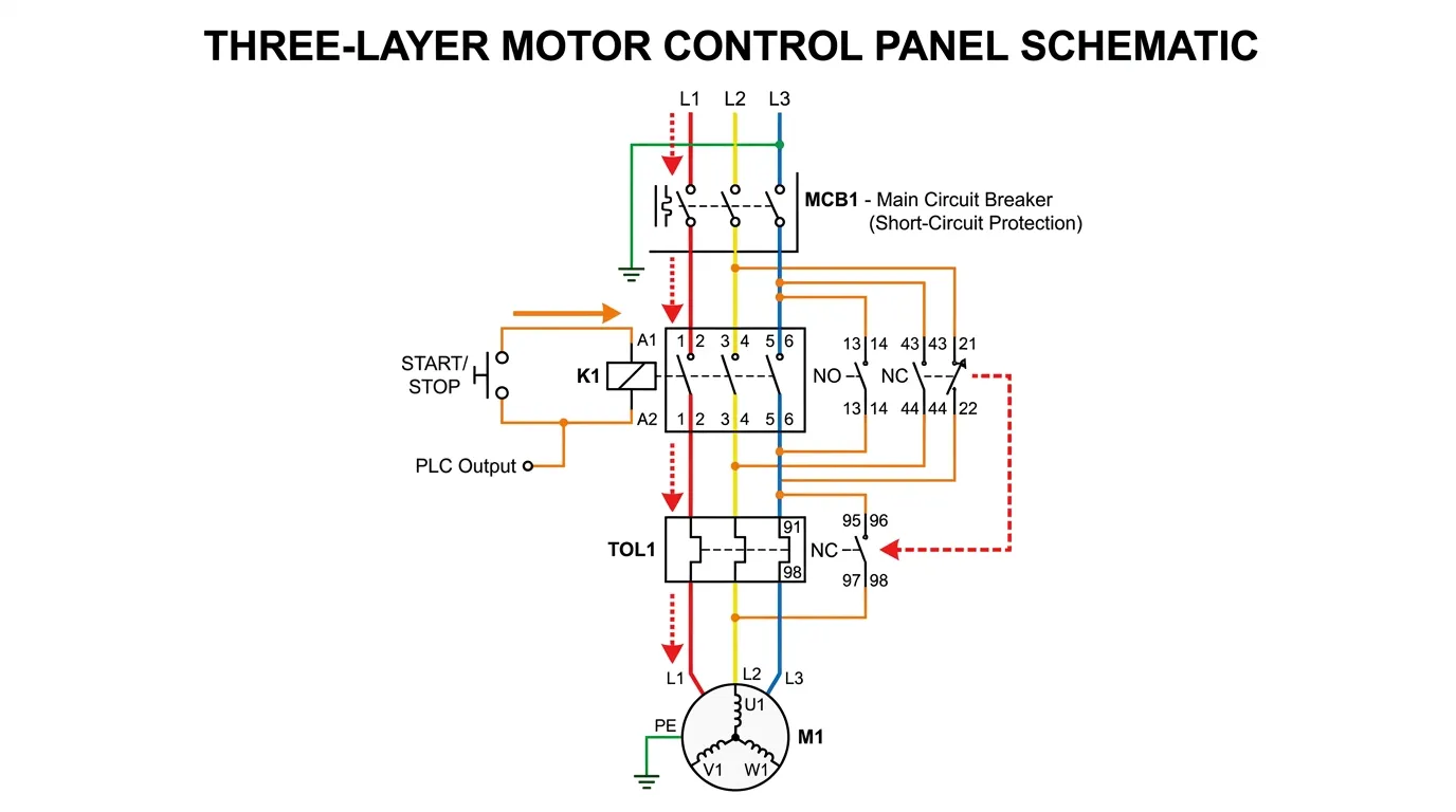
System Synergy: A three-layer motor control panel schematic demonstrating how the main circuit breaker (MCB1), contactor (K1), and thermal overload relay (TOL1) integrate to offer comprehensive control and protection.
Motor control is the application where the contactor vs circuit breaker relationship becomes most clear — and where most misapplications occur.
A properly designed motor feeder or starter assembly typically includes three layers of protection and control:
Circuit Breaker (or Fuses) — provides short-circuit protection for the motor branch circuit. Sized to handle motor inrush without nuisance tripping while still clearing downstream faults within conductor damage limits.
Contactor — provides routine switching control. Starts and stops the motor on command from the control system, push buttons, PLC, or automation logic. Designed for the switching frequency the application demands.
Overload Relay — provides thermal overload protection for the motor. Monitors running current and trips the contactor if the motor draws excessive current for too long, protecting the motor windings from thermal damage.
Each device covers a different failure mode:
Failure Mode
Protected By
Why This Device?
Short circuit (thousands of amps)
Circuit breaker
Only device with sufficient interrupting capacity
Sustained overload (110–600% of rated current)
Overload relay
Calibrated thermal model matches motor heating characteristics
Normal start/stop operations
Contactor
Designed for millions of switching operations
Phase loss or imbalance
Overload relay (with differential sensing)
Detects asymmetric current conditions
Control circuit command
Contactor
Responds to external control signals
When one device is forced to cover all three roles, the result is always a compromise. A breaker used as the routine start/stop switch wears out prematurely. A contactor expected to clear short-circuit faults may weld its contacts or explode. An overload relay without an upstream breaker has no protection against high-magnitude faults.
Engineering Principle: Good motor protection design separates the protection function (breaker), the control function (contactor), and the overload management function (overload relay) so that each device operates within its design envelope.
The 5 Most Common Misapplications (and Their Consequences)
Misapplication 1: Using a Circuit Breaker for Routine Motor Switching
What happens: A facility manager or cost-focused designer eliminates the contactor and uses the branch circuit breaker as the daily on/off switch for a motor.
Why it fails: Circuit breakers are rated for approximately 10,000–25,000 mechanical operations. A motor that starts 10 times per day exceeds the breaker’s mechanical life in 3–7 years. But the electrical contact life under motor inrush is far shorter — often only 1,500–5,000 operations at rated current. The breaker contacts erode, resistance increases, and eventually the breaker either fails to close, fails to trip, or develops dangerous internal heating.
The fix: Install a properly rated contactor for switching duty, with the breaker serving only as the protective device upstream.
Misapplication 2: Using a Contactor Without Upstream Short-Circuit Protection
What happens: A contactor is installed to switch a load, but no circuit breaker or fuse is provided upstream.
Why it fails: If a downstream short circuit occurs, the contactor must try to interrupt a fault current it was never designed to handle. Standard contactors have limited short-circuit breaking capacity. The fault current can weld the contacts shut (the contactor cannot reopen), destroy the arc chute, or cause an arc flash event. With welded contacts, the load cannot be disconnected, creating a sustained hazard.
The fix: Always provide upstream short-circuit protective devices (SCPD) — either fuses or circuit breakers — rated for the available fault current at the installation point. The contactor’s short-circuit rating should be verified in combination with the selected SCPD.
Misapplication 3: Ignoring Utilization Category When Sizing Contactors
What happens: A contactor is selected based solely on its AC-1 (resistive load) current rating and installed on a motor circuit that requires AC-3 or AC-4 duty.
Why it fails: Motor inrush current during starting is 6–8× full load amperage. At AC-3 duty, the contactor must make against this inrush and break at running current — a far more demanding duty than resistive switching. At AC-4 duty (inching, plugging, reversing), the contactor must break at inrush current levels. A contactor undersized for the actual utilization category suffers rapid contact erosion, increased contact resistance, overheating, and premature failure.
The fix: Always match the contactor utilization category to the actual application. Use AC-3 for normal motor starting and AC-4 for severe motor duty. Derate appropriately.
Misapplication 4: Treating Overload Protection and Short-Circuit Protection as Identical
What happens: A designer assumes that because an MCCB has a thermal overload element, no separate overload relay is needed for motor protection.
Why it fails: An MCCB’s thermal element protects the conductor, not the motor. The MCCB is sized to the conductor ampacity (typically 125% or more of motor FLA), while a motor overload relay is calibrated to the motor’s actual full load current. A motor can overheat and sustain winding damage at current levels that are perfectly acceptable to the MCCB. Additionally, MCCB thermal elements do not provide phase-loss or phase-imbalance detection, which dedicated motor overload relays do.
The fix: Use dedicated motor overload relays calibrated to the motor’s actual FLA, in addition to the upstream breaker for short-circuit protection.
Misapplication 5: Assuming “It Can Open the Circuit” Equals “It Provides Protection”
What happens: A contactor is justified as a protective device because “it can open the circuit if the control power is removed.”
Why it fails: Protection is not merely about opening a circuit. It requires opening under the right conditions (specific overcurrent thresholds), at the right fault level (within the device’s interrupting capacity), with predictable coordination relative to other devices in the system. A contactor de-energized by a control signal does not clear a downstream short circuit — the fault current continues to flow through the still-closing contacts until something else (a breaker or fuse) interrupts it.
The fix: Design the protection architecture properly with devices rated and intended for protection duty. Use contactors for control, breakers for protection.
Selection Guidelines: How to Choose the Right Device
Contactor Selection — Step by Step
Step 1: Classify the Load
Determine the utilization category. Resistive heating? AC-1. Standard motor starting? AC-3. Inching, plugging, or reversing? AC-4. This is the most critical step and the one most often skipped.
Step 2: Determine the Required Current Rating
Use the rated current for the appropriate utilization category — not the headline (AC-1) rating. Apply a minimum 25% safety margin above the actual load current.
Step 3: Match the Voltage Ratings
Verify both the power circuit voltage rating (line voltage) and the control coil voltage. Ensure the coil voltage matches the available control power supply. See our guide on AC and DC contactor selection for detailed guidance.
Step 4: Define Auxiliary Contact Requirements
Specify the number and type (NO/NC) of auxiliary contacts needed for status indication, interlocking, and control circuit logic.
Step 5: Evaluate the Switching Frequency
Compare the required operations per hour against the contactor’s rated switching frequency for the load category. High-frequency applications may require oversized contactors or specialized high-endurance models.
Step 6: Verify the Coordination with Upstream Protection
Confirm that the contactor, combined with the selected upstream circuit breaker or fuses, achieves the required short-circuit withstand capability (coordination Type 1 or Type 2 per IEC 60947-4-1).
Type 1 coordination: The contactor may be damaged after a short circuit and require inspection or replacement. Lower cost.
Type 2 coordination: The contactor remains operational after a short circuit with no significant damage. Higher reliability, higher initial cost.
Circuit Breaker Selection — Step by Step
Step 1: Calculate the Continuous Current Requirement
Determine the maximum continuous load current. For motor circuits, this is typically 125% of the motor’s full load amperage per NEC 430 or the applicable standard.
Step 2: Determine the Available Fault Current
Calculate or obtain the prospective short-circuit current at the point of installation. The breaker’s interrupting capacity must exceed this value. See our guide on MCCB selection for panels for detailed methodology.
Step 3: Select the Trip Characteristics
Match the trip curve to the load:
B-curve MCB — sensitive loads, long cable runs, residential
C-curve MCB — general commercial/industrial loads with moderate inrush
Adjustable MCCB — when precise coordination with other devices is needed
Step 4: Evaluate Special Protection Needs
Determine if ground fault (GFCI/RCD), arc fault (AFCI/AFDD), or zone-selective interlocking is required. For the differences between MCBs and MCCBs, the choice depends on current rating, interrupting capacity, and adjustability requirements.
Step 5: Verify Selectivity and Coordination
Ensure the breaker coordinates properly with upstream and downstream protective devices so that only the nearest device to the fault trips — preserving power to unaffected circuits.
Step 6: Confirm Physical Compatibility
Verify panel space, bus connection type, wire termination sizes, and mounting method.
Installation Best Practices
Contactor Installation
Mount vertically in a properly rated enclosure (NEMA 1 minimum for indoor; NEMA 3R, 4, or 4X for outdoor or harsh environments)
Maintain clearances specified by the manufacturer for heat dissipation and arc gas venting
Use properly sized conductors based on the contactor’s terminal ratings, not just the load current
Install overload relays directly downstream of the contactor for motor protection applications
Provide control circuit protection — a dedicated fuse or MCB for the contactor coil circuit
Include status indication — pilot lights or auxiliary contact signals for operational monitoring
Verify coil voltage before energizing — incorrect coil voltage causes immediate coil failure (too high) or contact welding from insufficient holding force (too low)
Circuit Breaker Installation
Follow manufacturer torque specifications exactly for all terminal connections — loose connections are the leading cause of breaker overheating and panel fires
Verify interrupting capacity against the available fault current at the installation location
Maintain NEC 110.26 working clearances — 36 inches minimum in front of the panel for safe operation and maintenance
Label circuits clearly per NEC 408.4 requirements
Test trip functionality after installation using the breaker’s test button (for RCD/GFCI types) or by verifying proper operation
Troubleshooting: Contactor vs Circuit Breaker Common Issues
Contactor Troubleshooting Guide
Symptom
Likely Causes
Diagnostic Steps
Solutions
Contactor won’t close
No control power, failed coil, mechanical binding, blown control fuse
Measure coil voltage; check control circuit continuity; inspect for physical obstruction
Restore control power; replace coil; free mechanism; replace control fuse
Contactor buzzes or chatters
Low coil voltage, broken shading ring, contaminated pole faces
Measure voltage at coil terminals under load; inspect magnetic surfaces
Correct voltage supply; replace shading ring; clean or replace magnetic assembly
Contacts welding closed
Excessive inrush current, wrong utilization category, contacts near end of life, inadequate upstream protection
Check actual load current vs. rating; verify utilization category; inspect contact surfaces
Re-torque or replace connections; reduce load; replace breaker if internal heating persists
Breaker trips immediately on reset
Sustained short circuit or ground fault on load side
Disconnect all loads; reconnect one at a time to isolate the faulted circuit
Repair the faulted circuit before re-energizing
Cost and Lifecycle Analysis: Contactor vs Circuit Breaker
Understanding the total cost of ownership helps justify proper device selection over the false economy of substituting one for the other.
Contactor Lifecycle Economics
A quality 3-pole AC-3 contactor rated 95A typically costs $80–$200, with contact kits available for $20–$50. In a motor circuit cycling 20 times per day:
Electrical life at AC-3: ~1,000,000 operations ÷ 20 operations/day ÷ 365 days = ~137 years of contact life
Maintenance: Annual inspection, contact cleaning, and torque check — approximately 30 minutes of labor
Replacement contacts: Every 5–10 years in heavy-duty applications — $20–$50 per set
Circuit Breaker Lifecycle Economics
A quality MCCB rated 100A with 25kA interrupting capacity typically costs $150–$400. In a protection-only role:
Mechanical life: ~20,000 operations — ample for the few hundred operations expected over a 20–30 year service life
Maintenance: Trip testing every 3–5 years; thermographic scanning annually — approximately 15–30 minutes per test
Replacement: Typically at 20–30 year intervals unless tripped under fault conditions
The Cost of Misapplication
Using a $300 MCCB as a daily motor switch (20 cycles/day) depletes its 10,000 electrical operations in approximately 18 months. The breaker must then be replaced — at $300 plus labor, downtime, and the risk of protection failure before the replacement is made.
A $150 contactor performing the same switching duty lasts decades. The $150 “savings” from eliminating the contactor costs $300+ per replacement, plus production downtime, every 18 months.
Total 10-year cost comparison for a motor circuit switching 20 times/day:
The correct design costs half as much and delivers dramatically better reliability.
Frequently Asked Questions
What is the main difference between a contactor and a circuit breaker?
A contactor is designed for frequent switching and remote control of electrical loads during normal operation. A circuit breaker is designed for overcurrent protection — automatically interrupting the circuit when overload or short-circuit conditions occur. Contactors control; breakers protect. In most industrial applications, both devices work together.
Can I use a circuit breaker as a contactor to start and stop a motor every day?
Technically, a circuit breaker can open and close a circuit. However, it should not be used for frequent operational switching. Circuit breakers are rated for approximately 10,000–25,000 mechanical operations — adequate for occasional maintenance switching, but far too few for daily motor start/stop cycles. Using a breaker this way leads to accelerated contact wear, increased contact resistance, unreliable protection, and premature failure.
Can a contactor replace a circuit breaker for overcurrent protection?
No. A contactor has no inherent overload or short-circuit detection capability. It cannot sense abnormal current and trip automatically. Even if de-energized by an external signal, a contactor does not provide the calibrated, automatic overcurrent protection that codes and standards require. Short-circuit current can weld contactor contacts shut, creating a dangerous condition.
Why do motor starters use a breaker, contactor, AND overload relay?
Because each device addresses a different need: the breaker provides short-circuit protection (high-magnitude, fast-acting), the contactor provides switching control (frequent, remote operation), and the overload relay provides thermal overload protection (sustained moderate overcurrent calibrated to the motor’s thermal limits). This combination is more robust, safer, and longer-lasting than any single device attempting all three roles.
Why is utilization category important when selecting a contactor?
Because the type of load dramatically affects contact wear. A contactor rated 95A at AC-1 (resistive) may only be suitable for 60A at AC-3 (motor starting) and 40A at AC-4 (motor inching/reversing). Selecting based on AC-1 ratings for a motor application results in undersizing, leading to rapid contact erosion, overheating, welding, and premature failure.
What causes contactor contacts to weld together?
Contact welding typically results from: (1) excessive inrush current beyond the contactor’s utilization category rating, (2) inadequate upstream short-circuit protection allowing fault current to flow through the contactor, (3) voltage transients causing re-striking arcs, or (4) contacts at end of life with reduced contact material. Proper sizing, correct utilization category selection, and upstream protection prevent most welding incidents.
Is a contactor safer than a circuit breaker?
They are not comparable in terms of safety because they serve different safety functions. A contactor without upstream protection is unsafe. A circuit breaker forced into frequent switching duty is unsafe. Safety depends on each device being applied correctly within its design intent. In a well-designed system, both devices contribute to safety in their respective roles.
What is the difference between Type 1 and Type 2 coordination for motor starters?
Type 1 coordination (IEC 60947-4-1) allows the contactor and overload relay to be damaged during a short circuit, requiring inspection and possible replacement afterward. Type 2 coordination requires the starter to remain fully functional after a short circuit, with no damage beyond easily replaceable parts like contact tips. Type 2 costs more initially but provides higher uptime and lower lifecycle costs in critical applications.
How often should contactors and circuit breakers be maintained?
Contactors: Inspect annually in standard industrial environments — check contact condition, measure contact resistance, verify coil operation, re-torque connections, and clean arc chutes. High-duty applications may require semi-annual inspection.
Circuit breakers: Test trip function every 3–5 years using secondary injection testing. Perform annual thermographic scans and torque checks on connections. MCCBs and ACBs in critical applications should be exercised (operated open/close) annually to prevent mechanism sticking.
Are there devices that combine contactor and circuit breaker functions?
Yes. Motor protection circuit breakers (MPCBs) combine switching, overload, and short-circuit protection in a single device. They are compact and cost-effective for smaller motors. However, they typically have lower switching endurance than dedicated contactors and may not provide the same level of remote control flexibility. For high-frequency switching or complex automation requirements, the separate contactor-plus-breaker approach remains superior.
Conclusion: Contactor vs Circuit Breaker — Partners, Not Substitutes
The contactor vs circuit breaker comparison is not about choosing one over the other. It is about understanding that these devices solve fundamentally different problems and, in most industrial and commercial systems, work together as complementary partners.
A contactor is for controlled, frequent switching. It is the workhorse that starts motors, switches lighting, and responds to automation commands — day after day, millions of times over its service life.
A circuit breaker is for protective interruption. It is the guardian that sits quietly, carrying current safely, and intervenes decisively when overcurrent threatens the circuit — clearing faults that would destroy conductors, equipment, and potentially harm people.
The key takeaways for every electrical professional:
Never substitute one for the other. A contactor cannot protect. A breaker cannot switch frequently.
Size contactors by utilization category, not headline current ratings. AC-3 for motors, AC-4 for severe duty.
Size breakers by interrupting capacity and trip characteristics, not just continuous current rating.
Motor circuits need both — plus an overload relay — for complete protection and control.
The total cost of correct design is always lower than the cost of misapplication, premature failure, and unplanned downtime.
When you design with each device performing the job it was built for, you get panels that are safer, more reliable, less expensive to maintain, and fully compliant with applicable codes and standards.
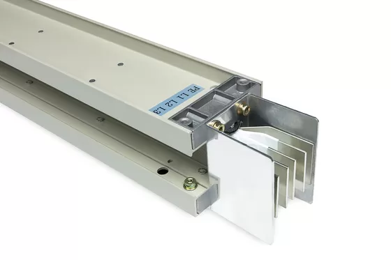
A busbar is a bare or insulated conductor that distributes electrical power within a single enclosure, while a busway is a complete prefabricated system of enclosed conductors with protective housing designed for power distribution across longer distances and multiple connection points.
Understanding the difference between busbars and busways is critical for electrical engineers, contractors, and facility managers making power distribution decisions. This guide provides comprehensive technical comparisons, safety requirements, and selection criteria to help you choose the right solution for your specific application.
What is a Busbar? Complete Definition and Technical Overview
A busbar is a metallic conductor, typically made of copper or aluminum, designed to carry large electrical currents within electrical panels, switchgear, and distribution equipment. Busbars serve as central collection points where multiple electrical circuits connect to distribute power throughout a facility.
Key Technical Characteristics:
Material: Primarily copper (higher conductivity) or aluminum (cost-effective)
Configuration: Flat strips, rectangular bars, or tubular conductors
Current Rating: 100 amperes to over 6,000 amperes
Installation Location: Inside electrical enclosures and panelboards
Protection: Relies on enclosure for environmental protection
What is a Busway? Complete Definition and System Overview
A busway is a prefabricated electrical distribution system consisting of busbars enclosed in a protective metal housing with standardized connection points called tap-off boxes. Busways provide a modular, flexible approach to power distribution that can be easily modified or expanded.
Key System Components:
Conductor Assembly: Copper or aluminum busbars with proper phase spacing
Protective Housing: Grounded metal enclosure providing environmental protection
Tap-Off Connections: Standardized connection points for branch circuits
Support Systems: Mounting brackets and suspension hardware
Current Rating: 225 amperes to 5,000+ amperes for industrial applications
Busbar vs Busway: Comprehensive Technical Comparison
Feature
Busbar
Busway
Definition
Bare or insulated conductor within enclosure
Complete prefabricated distribution system
Installation Location
Inside panels and switchgear
Open installation along walls/ceilings
Flexibility
Fixed installation, difficult to modify
Modular design, easily reconfigured
Current Range
100A – 6,000A+
225A – 5,000A+
Cost (Initial)
Lower material cost
Higher initial investment
Labor Requirements
High field installation time
Reduced installation time
Tap-Off Capability
Limited connection points
Multiple standardized tap points
Code Requirements
NEC Article 408 (panels)
NEC Article 368 (busways)
Environmental Protection
Depends on enclosure
Integral weatherproof housing
Modification Ease
Requires panel shutdown
Hot tap capability available
Space Requirements
Compact within enclosures
Requires dedicated routing space
Key Differences Between Busbars and Busways
1. Installation Method and Flexibility
Busbars require field fabrication and installation within electrical enclosures. Once installed, modifications require significant electrical work and potential system shutdowns. This makes busbars ideal for permanent installations with fixed power requirements.
Busways arrive as prefabricated sections that bolt together using standardized connections. The modular design allows for easy reconfiguration, expansion, or relocation without major electrical work, making them perfect for dynamic industrial environments.
2. Power Distribution Philosophy
Busbars serve as central collection points within electrical equipment, connecting multiple branch circuits to main power sources. They function as the backbone of traditional panelboard and switchgear designs.
Busways act as electrical highways, carrying power from main distribution points to various locations throughout a facility. They replace traditional cable and conduit runs for high-amperage applications.
3. Connection and Tap-Off Capabilities
Busbars offer limited connection points determined during initial design and installation. Adding new connections typically requires panel modifications and system downtime.
Busways provide multiple tap-off points along their length, with some systems offering “hot tap” capability for adding connections while energized (when performed by qualified personnel following proper safety procedures).
Applications and Use Cases: When to Choose Each System
Optimal Busbar Applications
Industrial Control Panels
Motor control centers requiring compact design
Process control systems with fixed configurations
UL-listed panel assemblies requiring standard compliance
Switchgear Applications
High-voltage distribution equipment
Utility interconnections requiring maximum current density
Critical power systems prioritizing reliability over flexibility
Data Center Power Distribution
PDU internal connections requiring space efficiency
Critical systems requiring UL-listed assemblies
High-density installations with limited modification needs
Ideal Busway Applications
Manufacturing Facilities
Production lines requiring flexible power distribution
Require UL-listed assemblies for commercial installations
Must include proper support spacing (typically 5-foot intervals)
Need appropriate overcurrent protection at origin point
Require grounding conductor throughout system length
⚠️ SAFETY WARNING: All electrical work involving busbars and busways must be performed by qualified electricians following NFPA 70E standards. High-amperage systems present serious arc flash and electrocution hazards.
Installation Safety Considerations
Critical Safety Factors:
Arc Flash Assessment: Required for all busbar and busway work
Proper PPE: Category-rated clothing and equipment based on incident energy
Lockout/Tagout: Mandatory for all maintenance and modification work
Qualified Personnel: Only licensed electricians should perform installations
Code Compliance: Local electrical codes may have additional requirements
Selection Criteria: How to Choose Between Busbars and Busways
Choose Busbars When:
Fixed Installation Requirements
Permanent power distribution with no anticipated changes
Space-constrained applications requiring maximum compactness
UL-listed panel assemblies required for insurance or code compliance
Cost-Sensitive Projects
Lower initial material costs are priority
Simple point-to-point power distribution needs
High current density applications with limited connection points
Traditional Electrical Infrastructure
Integration with existing panelboard systems
Replacement of existing busbar assemblies
Applications requiring standard electrical panel form factors
Choose Busways When:
Flexibility and Future Expansion Needs
Anticipated layout changes or equipment relocations
Growing facilities requiring scalable power infrastructure
Multi-tenant buildings with changing power requirements
High-Current Distribution Over Distance
Power feeds exceeding 400 amperes over 50+ feet
Multiple tap-off points along distribution path
Overhead installation preferred over floor-level panels
Rapid Installation Requirements
Projects with tight construction schedules
Retrofit installations minimizing existing system disruption
Modular construction requiring standardized connections
Expert Tips for Optimal Selection and Implementation
? Professional Selection Guidelines
Conduct Thorough Load Analysis: Calculate not just current requirements but also future expansion needs. Busways excel when growth potential exceeds 25% of initial capacity.
Evaluate Total Cost of Ownership: While busways have higher initial costs, consider reduced installation time, easier modifications, and improved system flexibility over 20+ year lifespan.
Consider Environmental Factors: Busways with appropriate NEMA ratings handle harsh environments better than enclosed busbars requiring additional protection.
Plan for Maintenance Access: Busways provide superior maintenance access compared to densely packed panelboards, reducing long-term service costs.
⚠️ Critical Safety Reminders
Never Compromise on Safety Standards: Both busbars and busways carry lethal voltages and currents. Always follow NFPA 70E requirements and use qualified personnel.
Verify Proper Grounding: Inadequate grounding in high-current systems creates serious safety hazards. Ensure continuous equipment grounding throughout system.
Maintain Proper Documentation: Keep accurate as-built drawings showing conductor arrangements, ratings, and connection points for future maintenance and modifications.
Quick Reference: Specification Comparison Chart
Specification
Typical Busbar Range
Typical Busway Range
Current Rating
100A – 6,000A
225A – 5,000A
Voltage Rating
120V – 600V
120V – 600V
Material Options
Copper/Aluminum
Copper/Aluminum
Installation Cost
$2-8 per amp
$8-15 per amp
Modification Cost
High (panel work)
Low (plug-in taps)
Typical Lifespan
30+ years
25+ years
Lead Time
2-6 weeks
4-8 weeks
Troubleshooting Common Issues
Busbar Installation Problems
Overheating Issues
Cause: Inadequate conductor sizing or poor connections
Solution: Verify calculations per NEC Table 310.15(B)(16) and inspect all connections
Space Constraints
Cause: Insufficient clearances for NEC requirements
Solution: Review NEC Table 408.5 for minimum spacing requirements
Busway System Challenges
Connection Problems
Cause: Misaligned sections or contaminated contact surfaces
Solution: Follow manufacturer’s torque specifications and use contact cleaner
Voltage Drop Issues
Cause: Excessive system length without proper sizing
Solution: Calculate voltage drop per NEC Chapter 9, Table 9 and upsize conductors if needed
Professional Installation Recommendations
When to Consult Electrical Engineers
Complex Systems Requiring Design Analysis
High-fault current applications exceeding 65kA
Critical power systems requiring redundancy
Integration with existing electrical infrastructure
Code Compliance Questions
Local amendments to NEC requirements
Special occupancy requirements (healthcare, hazardous locations)
Utility interconnection standards
Recommended Certification Requirements
Installer Qualifications
Licensed journeyman electrician minimum
NFPA 70E training certification
Manufacturer-specific training for busway systems
Frequently Asked Questions
What makes busways more expensive than busbars initially?
Busways cost more initially because they include protective housing, standardized connections, and factory assembly. However, they often provide better long-term value through reduced installation time and easier modifications.
Can you mix different manufacturers’ busway components?
No, busway systems are not interchangeable between manufacturers. Each system uses proprietary connection methods and specifications. Always use components from the same manufacturer for proper fit and UL listing compliance.
How do you determine the right current rating for your application?
Calculate your total connected load, apply appropriate demand factors per NEC Article 220, and add 25% for future expansion. Always consult with qualified electrical engineers for complex calculations.
What are the maintenance requirements for each system?
Busbars require periodic inspection within enclosed panels, checking for loose connections and overheating. Busways need regular cleaning of housing, connection inspection, and verification of support integrity.
Can busways be installed outdoors?
Yes, busways are available with appropriate NEMA ratings for outdoor installation (NEMA 3R, 4, 4X). Ensure proper weatherproofing at all connection points and follow manufacturer’s installation guidelines.
How long do busbar and busway systems typically last?
Both systems can last 25-30+ years with proper maintenance. Busways may have slightly shorter lifespans due to environmental exposure, while enclosed busbars benefit from protection within electrical panels.
What safety training is required for working on these systems?
All personnel must complete NFPA 70E electrical safety training appropriate for their qualification level. Arc flash assessments are mandatory, and proper PPE must be worn based on incident energy calculations.
Are there special considerations for seismic zones?
Yes, both systems require proper seismic bracing per local building codes. Busways need additional support points and flexible connections at building joints. Consult structural engineers for seismic zone installations.
Expert Conclusion and Next Steps
Choosing between busbars and busways depends on your specific application requirements, future expansion plans, and budget considerations. Busbars excel in permanent, space-constrained installations where cost is paramount, while busways provide superior flexibility and ease of modification for dynamic environments.
For complex power distribution decisions, always consult with qualified electrical engineers who can perform detailed load calculations, fault current analysis, and code compliance verification. Proper selection and installation of these critical power distribution components ensures safe, reliable electrical systems that serve your facility for decades.
Ready to implement the right power distribution solution? Contact licensed electrical professionals to evaluate your specific requirements and develop detailed specifications that meet all safety codes and performance objectives.
Circuit breakers do NOT protect people from electrical shock or electrocution. This widespread misconception puts lives at risk every day. Circuit breakers are designed exclusively to protect your home’s electrical equipment and wiring from damage caused by overcurrent conditions—not to save human lives from electrical hazards.
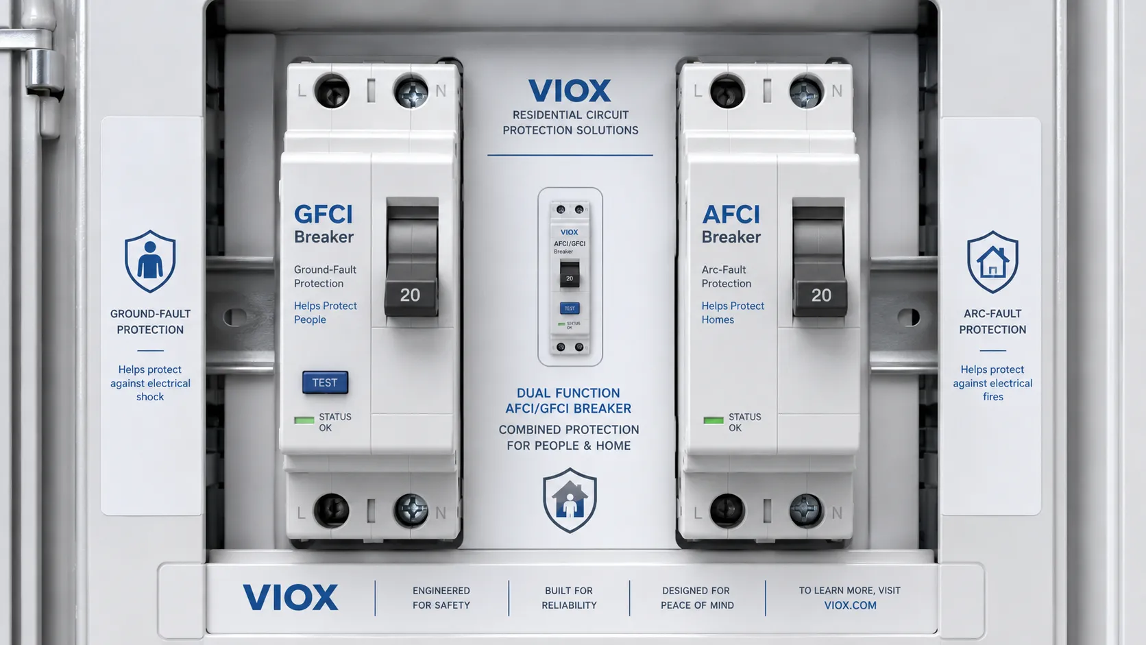
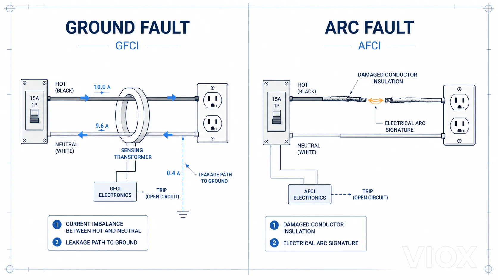
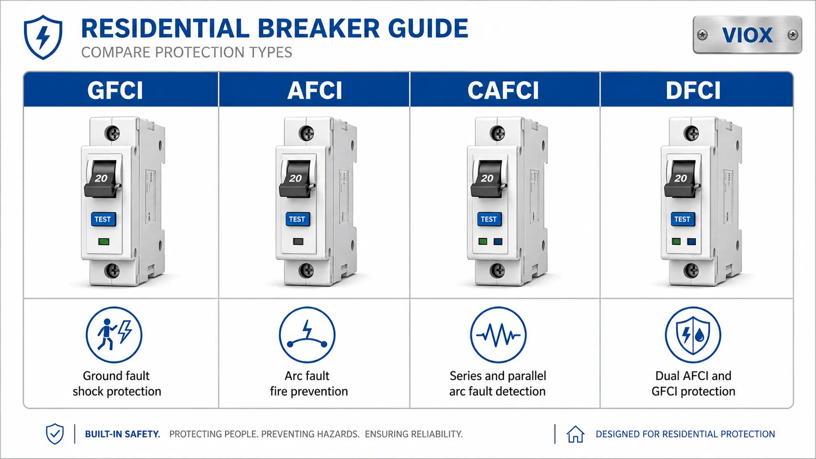
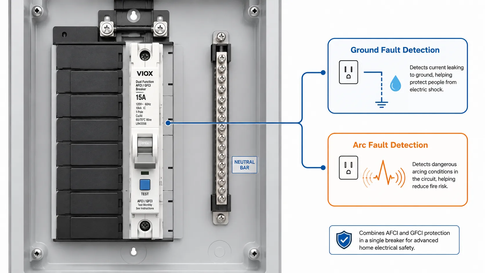
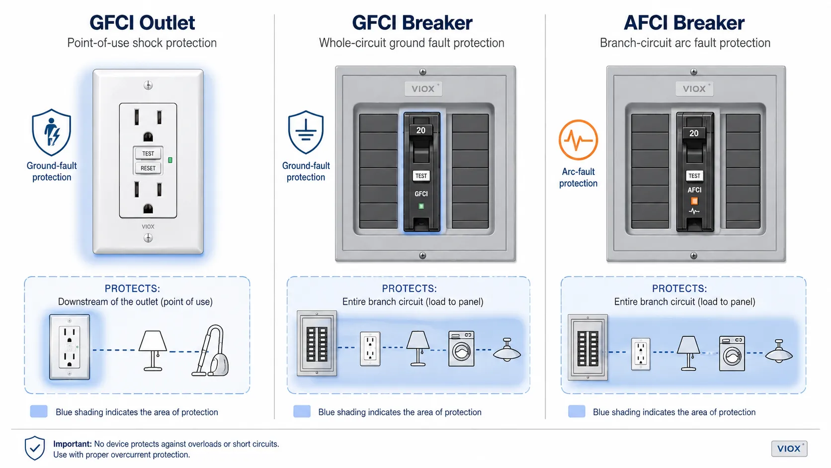
Understanding this critical distinction could literally save your life or the life of someone you love. While circuit breakers prevent electrical fires and equipment damage, Ground Fault Circuit Interrupters (GFCIs) and Arc Fault Circuit Interrupters (AFCIs) are the devices that actually protect people from electrical hazards.
VIOX Circuit Breaker
What Circuit Breakers Actually Do: Equipment Protection, Not Human Safety
The Real Purpose of Circuit Breakers
Circuit breakers serve as automatic switches that protect electrical circuits from damage caused by:
Overcurrent conditions (when too much electrical current flows through a circuit)
Short circuits (when hot and neutral wires touch)
Overloads (when too many devices draw power from one circuit)
⚡ SAFETY WARNING: Never rely on circuit breakers for personal electrical safety. They cannot and will not protect you from electrical shock or electrocution.
How Circuit Breakers Work vs. Human Protection Needs
Function
Circuit Breaker Response
Human Safety Requirement
Detection Time
1-5 seconds for overload
30 milliseconds maximum for human safety
Current Threshold
15-20+ amps (15,000-20,000+ milliamps)
5 milliamps can be fatal to humans
Protection Type
Equipment and fire prevention
Personal shock and electrocution prevention
Trip Mechanism
Thermal or magnetic response to high current
Ground fault or arc fault detection required
The Dangerous Misconception: Why People Think Circuit Breakers Protect Them
Common Myths About Circuit Breaker Protection
Myth 1: “If I get shocked, the circuit breaker will trip and save me” Reality: Circuit breakers trip at 15-20+ amps; 50 milliamps can kill you
Myth 2: “Circuit breakers prevent all electrical accidents” Reality: They only prevent equipment damage and fires, not human contact hazards
Myth 3: “Old homes with circuit breakers are electrically safe” Reality: Without GFCIs and AFCIs, people remain vulnerable to fatal electrical hazards
The Mathematical Reality: Current Levels and Human Safety
Here’s the stark comparison that reveals why circuit breakers can’t protect people:
Current Level
Effect on Humans
Circuit Breaker Response
1 milliamp
Barely perceptible
No response
5 milliamps
Maximum safe current
No response
10-20 milliamps
Muscular control lost
No response
50 milliamps
Ventricular fibrillation (often fatal)
No response
100-200 milliamps
Certain death
No response
15,000+ milliamps (15 amps)
Circuit breaker finally trips
FAR TOO LATE
What Actually Protects People: GFCI and AFCI Devices
Ground Fault Circuit Interrupters (GFCIs): Your Lifeline
GFCIs detect imbalances in electrical current as small as 4-6 milliamps and shut off power in 25-30 milliseconds—fast enough to prevent fatal electrocution.
Required GFCI Locations (NEC Code):
Bathrooms (all receptacles)
Kitchens (countertop receptacles)
Garages and unfinished basements
Outdoor receptacles
Crawl spaces and unfinished basements
Laundry areas
Arc Fault Circuit Interrupters (AFCIs): Fire and Shock Prevention
AFCIs detect dangerous electrical arcs that can cause fires and electrocution, providing protection that standard circuit breakers cannot offer.
AFCI Requirements:
All bedrooms (required since 2002)
Most living areas (required since 2014)
Kitchens, family rooms, dining rooms, and similar spaces
Critical Safety Comparison: Circuit Breakers vs. Life-Saving Devices
Device Type
Primary Protection
Response Time
Current Threshold
Human Safety Level
Circuit Breaker
Equipment/Fire
1-5 seconds
15-20+ amps
❌ NONE
GFCI
Human shock protection
25-30 milliseconds
4-6 milliamps
✅ EXCELLENT
AFCI
Arc detection
<1 second
Arc signatures
✅ VERY GOOD
AFCI+GFCI Combo
Comprehensive protection
<30 milliseconds
Both arc and ground faults
✅ MAXIMUM
Where Circuit Breakers Fail to Protect People: Real-World Scenarios
Scenario 1: Bathroom Hair Dryer Accident
What Happens: Person drops hair dryer in sink with water Circuit Breaker Response: No protection—current flows through water and person GFCI Response: Immediately cuts power, prevents electrocution Outcome Without GFCI: Potential fatality
Scenario 2: Damaged Extension Cord
What Happens: Frayed outdoor extension cord contacts wet ground while person touches it Circuit Breaker Response: No protection—ground fault current too low to trip breaker GFCI Response: Detects ground fault, instantly shuts off power Outcome Without GFCI: Severe shock or death
Article 210.12 – AFCI Protection:
Required in bedrooms since 2002
Extended to most living areas since 2014
Must be combination-type AFCIs
Article 210.8 – GFCI Protection:
Bathrooms: All receptacles
Kitchens: Countertop receptacles within 6 feet of sink
Outdoors: All receptacles
Garages: All receptacles
⚠️ PROFESSIONAL REQUIREMENT: GFCI and AFCI installation must be performed by licensed electricians to ensure proper protection and code compliance.
How to Identify Your Current Protection Level
Step-by-Step Safety Assessment
1. Locate Your Electrical Panel
Identify circuit breakers (these provide NO human protection)
Look for GFCI and AFCI breakers (these DO protect people)
2. Test GFCI Outlets Monthly
Press “TEST” button—power should cut off
Press “RESET” button—power should restore If this doesn’t work, replace immediately
3. Check for AFCI Protection
Look for AFCI breakers in electrical panel
Check for combination AFCI/GFCI devices
4. Professional Electrical Inspection Recommended every 10 years minimum
Required when buying/selling homes
Essential for homes built before 2000
Expert Tips for Maximum Electrical Safety
✅ DO:
Install GFCI protection in all required locations
Test GFCI devices monthly
Upgrade to combination AFCI/GFCI breakers when possible
Have electrical systems inspected by licensed professionals
Replace any non-functioning GFCI or AFCI devices immediately
❌ DON’T:
Assume circuit breakers provide personal protection
Ignore tripping GFCI devices (they’re detecting real hazards)
Use extension cords as permanent wiring
Work on electrical systems without proper training and tools
Disable or bypass GFCI or AFCI protection
The Financial Reality: Protection Costs vs. Lives
Cost Comparison for Life-Saving Protection
Protection Type
Installation Cost
Coverage
Value
GFCI Outlet
$15-50 + labor
Single location
Priceless life protection
GFCI Breaker
$50-100 + labor
Entire circuit
Multiple location protection
AFCI Breaker
$40-80 + labor
Arc fault protection
Fire and shock prevention
Combo AFCI/GFCI
$80-150 + labor
Complete protection
Maximum safety investment
Expert Insight: The cost of proper electrical protection is less than most home repairs, yet it provides protection against injuries and deaths that are truly priceless.
Upgrading Your Electrical Safety: Implementation Guide
Phase 1: Immediate Priority Areas
Bathrooms: Install GFCI protection for all outlets
Kitchen: GFCI protection for countertop receptacles
Outdoor areas: GFCI protection for all outdoor outlets
Garage: GFCI protection for all receptacles
Phase 2: Comprehensive Protection
Bedrooms: AFCI protection (required by code)
Living areas: AFCI protection for fire prevention
Basement/crawl spaces: GFCI protection for safety
Workshop areas: Both GFCI and AFCI protection
Phase 3: Advanced Protection
Whole-house surge protection
Combination AFCI/GFCI devices where applicable
Smart electrical monitoring systems
Professional electrical inspection and certification
Troubleshooting Common Protection Issues
GFCI Device Problems
Problem: GFCI won’t reset Cause: Active ground fault or damaged device Solution: Have licensed electrician diagnose and repair
Problem: GFCI trips frequently Cause: Moisture, damaged wiring, or faulty appliances Solution: Professional inspection required—don’t ignore this warning
Problem: No GFCI protection in required areas Cause: Older electrical installation Solution: Immediate upgrade by licensed electrician
Professional Recommendations and Next Steps
When to Call a Licensed Electrician
Immediate Professional Help Required:
Any electrical shock incident
Frequent GFCI or AFCI tripping
Burning smells or sparks from outlets
Outlets or switches that feel warm
Any exposed wiring or damaged electrical components
Recommended Professional Services:
Electrical safety inspection (every 10 years)
GFCI/AFCI installation in all required locations
Electrical panel upgrade for older homes
Whole-house electrical safety assessment
Certification and Training Requirements
Only licensed, insured electricians should perform electrical installations. Verify:
Current electrical license
Proper insurance coverage
Local permit requirements
Code compliance certification
Frequently Asked Questions
What’s the difference between a circuit breaker and GFCI protection?
Circuit breakers protect equipment and prevent fires by detecting overcurrent conditions (15-20+ amps). GFCIs protect people by detecting tiny current leaks (4-6 milliamps) that can cause electrocution, responding 500+ times faster than circuit breakers.
Can I install GFCI protection myself?
No. GFCI installation requires electrical expertise to ensure proper wiring, grounding, and code compliance. Improper installation can create deadly hazards. Always use licensed electricians for electrical safety devices.
How often should I test GFCI devices?
Monthly testing is required for all GFCI devices. Press the TEST button (power should cut off), then RESET (power should restore). If this doesn’t work properly, replace the device immediately.
Do older homes need GFCI and AFCI protection?
Absolutely. Older homes are at higher risk for electrical hazards. While retrofitting isn’t always required by code, it’s essential for safety. Many insurance companies now require GFCI protection in key areas.
What happens if I ignore GFCI requirements?
Beyond the obvious safety risks, you may face insurance claim denials, failed home inspections, legal liability for accidents, and violations of local electrical codes.
Can circuit breakers and GFCIs work together?
Yes, and they should. Circuit breakers provide overcurrent protection while GFCIs provide ground fault protection. Both are necessary for complete electrical safety—they serve completely different protective functions.
How long do GFCI and AFCI devices last?
GFCI devices: 10-15 years with proper maintenance AFCI devices: 15-20 years typical lifespan Both require regular testing and immediate replacement if they fail testing.
What should I do if my GFCI keeps tripping?
Never ignore a tripping GFCI—it’s detecting a real ground fault hazard. Disconnect all devices from the circuit and call a licensed electrician immediately. A tripping GFCI is protecting you from potential electrocution.
Conclusion: Your Life Depends on Understanding This Difference
Circuit breakers do not protect people—they protect equipment and prevent fires. This fundamental misunderstanding puts countless lives at risk every day. Only GFCI and AFCI devices provide the rapid response necessary to prevent electrocution and electrical fires.
The bottom line: If your home lacks proper GFCI and AFCI protection, you’re living with hidden electrical hazards that could prove fatal. The cost of proper protection is minimal compared to the value of your life and your family’s safety.
Take action today: Have a licensed electrician assess your electrical safety and install proper protection devices. Your life may literally depend on it.
Professional Consultation: For electrical safety assessments and GFCI/AFCI installation, contact licensed electricians in your area. Ensure all work meets current NEC codes and local requirements.
A circuit breaker pan assembly is a modular electrical distribution component that integrates rigid copper or aluminum busbars with structured mounting systems for circuit breakers, providing organized and efficient power distribution in electrical panels and distribution boards. These assemblies replace traditional point-to-point wiring with a systematic busbar approach, reducing installation time by 30-50% while enhancing safety and maintainability in residential, commercial, and industrial applications.
A circuit breaker pan assembly is the foundational component of modern distribution boards that houses circuit breakers in a structured, integrated busbar system. Think of it as the organized backbone of your electrical panel – instead of having individual wires connecting each circuit breaker to the main power source, the pan assembly uses rigid metal conductor bars (busbars) to distribute electricity efficiently and safely.
Key Components of a Circuit Breaker Pan Assembly:
Integrated busbar system: Rigid copper or aluminum conductor bars that carry electrical current
Modular mounting framework: Structured system with standardized spacing for circuit breakers
Phase identification system: Color-coded labeling (typically red, yellow, blue for phases and black for neutral)
Insulating housing: High-grade materials like PA66 or ABS providing electrical isolation
Terminal connection points: Standardized interfaces for incoming and outgoing circuits
Mounting hardware: Brackets and supports for secure panel installation
Understanding Pan Assembly Configurations
Single-Phase Pan Assemblies
Single-phase pan assemblies are designed for residential and light commercial applications where power demands are modest. These systems typically handle:
Specifications:
Current Range: 100A to 200A
Circuit Positions: 4 to 24 ways (positions for circuit breakers)
Voltage Rating: 230V AC standard
Applications: Residential homes, small offices, retail shops
Three-Phase Pan Assemblies
Three-phase configurations serve commercial and industrial applications requiring balanced power distribution across multiple phases:
Specifications:
Current Range: 125A to 225A and higher
Circuit Positions: 4 to 42 ways in modular increments
Voltage Rating: 400V AC three-phase
Circuit Breaker Types: 1P, 3P, and combination configurations
Applications: Office buildings, manufacturing facilities, data centers
Four-Phase Pan Assemblies
Four-phase systems include three power phases plus a neutral, offering maximum flexibility for mixed loading:
Specifications:
Current Range: 160A to 225A
Circuit Positions: Up to 36 ways for complex installations
⚠️ Safety Warning: Circuit breaker pan assembly installation requires licensed electricians due to electrical safety requirements and code compliance obligations.
Key Installation Considerations
Environmental Assessment
Adequate ventilation for heat dissipation
Protection from moisture and contaminants
Sufficient working clearance per NEC 110.26
Mechanical Installation
Secure mounting to appropriate structural supports
Proper alignment of busbar connections
Verification of mechanical integrity
Electrical Connections
Incoming connections: Properly sized conductors for main current rating
Neutral and ground connections: Separate paths with proper bonding
Load Distribution Planning
Balanced loading across phases in three-phase systems
Consideration of future expansion requirements
Proper circuit labeling per NEC Article 408.4(A)
Wire Connection Specifications
Incoming Conductors:
Neutral wiring: Up to 50mm² soft or hard wire capacity
Ground connections: Up to 16-35mm² depending on configuration
Phase conductors: Sized per main busbar current rating
Outgoing Connections:
Branch circuits: Up to 16mm² for individual circuit connections
Flexible connection options: Support for both rigid and flexible conductors
Advantages of Circuit Breaker Pan Assemblies
Enhanced Safety and Compliance
Pan assemblies use flame-retardant materials and provide electrical isolation between components, significantly reducing fire risk and electrical accidents. The systematic design ensures compliance with electrical safety standards.
Superior Organization and Efficiency
The modular design eliminates complex wiring tasks, allowing electricians to work more efficiently while reducing potential installation errors. Color-coded phase identification prevents wiring mistakes.
Economic Benefits
Cost Factor
Pan Assembly
Traditional Wiring
Material Costs
15-25% higher initial investment
Standard baseline cost
Installation Labor
50-60% reduction in time
Standard installation time
Maintenance Costs
40-50% lower over lifecycle
Higher maintenance complexity
Future Modifications
70% cost reduction for additions
Often requires complete rewiring
Scalability and Future-Proofing
Pan assemblies offer exceptional flexibility for system modifications. Adding new circuits becomes straightforward compared to traditional wiring methods that often require extensive panel modifications.
Selection Criteria for Circuit Breaker Pan Assemblies
Load Analysis and Sizing
Residential Applications:
Calculate total connected load using NEC Article 220
Add 25% safety margin for future expansion
Consider peak demand factors for realistic sizing
Commercial Applications:
Perform detailed load calculations including HVAC, lighting, and equipment loads
Factor in diversity factors for different load types
Local electrical codes: Regional compliance requirements
Common Installation Challenges and Solutions
Circuit Breaker Compatibility Issues
Problem: Installing incompatible circuit breakers violates NEC 110.3(B) and voids product listings.
Solution: Always verify manufacturer compatibility charts and maintain consistent brand specifications throughout the assembly.
Thermal Management Concerns
Problem: Inadequate heat dissipation in high-current applications.
Solution: Ensure proper ventilation clearances. Consider derating factors for ambient temperature. Use appropriate conductor sizing for heat generation.
Load Balancing in Three-Phase Systems
Problem: Unbalanced loads causing neutral current and inefficient operation.
Solution: Distribute single-phase loads evenly across phases. Monitor phase currents during commissioning. Implement load balancing strategies for variable loads.
Maintenance and Safety Guidelines
Regular Inspection Schedule
Monthly Visual Inspections:
Check for signs of overheating (discoloration, burning odors)
Verify secure mounting and connections
Inspect for environmental damage or contamination
Annual Professional Inspections:
Infrared thermography to detect hot spots
Torque verification on all connections
Insulation resistance testing
Documentation of any deterioration
Safety Procedures
⚠️ Critical Safety Warning: Never perform maintenance on energized pan assemblies. Always de-energize systems, verify absence of voltage, and implement proper lockout/tagout procedures.
Required Safety Equipment:
Personal protective equipment (PPE) rated for arc flash
Voltage testing devices with proper CAT ratings
Insulated tools appropriate for electrical work
Emergency communication equipment
Industry Applications and Use Cases
Residential Installations
Single-Family Homes:
Main electrical panels with 20-40 circuit capacity
Sub-panels for additions and outbuildings
Integration with smart home automation systems
Solar power system integration points
Multi-Unit Residential:
Individual unit panels with standardized configurations
Master distribution systems for common areas
Emergency power integration capabilities
Commercial Applications
Office Buildings:
Floor-by-floor distribution systems
Integration with building management systems
Flexible tenant space configurations
Energy monitoring and sub-metering capabilities
Retail Facilities:
Flexible lighting and power distribution
Seasonal load accommodation
Point-of-sale system integration
Security system power distribution
Industrial Applications
Manufacturing Facilities:
Motor control center integration
Process equipment power distribution
Emergency shutdown system compatibility
Maintenance accessibility in industrial environments
Data Centers:
Redundant power distribution systems
High-density circuit arrangements
Remote monitoring integration
Rapid fault isolation capabilities
Expert Tips for Optimal Performance
? Pro Tip: Design pan assemblies with 20-30% spare capacity for future expansion. This prevents costly upgrades as electrical demands grow.
? Pro Tip: Implement a consistent phase rotation and color-coding scheme throughout the facility to simplify maintenance and reduce errors.
? Pro Tip: Document all circuit assignments and modifications with updated electrical drawings. This is essential for future maintenance and compliance inspections.
? Pro Tip: Consider thermal imaging during initial commissioning to establish baseline temperatures for ongoing maintenance programs.
Economic Impact and Return on Investment
Initial Investment Analysis
While pan assemblies require 15-25% higher initial material costs, the total project economics favor their use:
Labor Cost Savings:
50-60% reduction in installation time
Reduced skilled labor requirements for modifications
Lower error rates requiring rework
Long-term Value Creation:
Enhanced system reliability reducing downtime costs
Most installations achieve return on investment within 2-3 years through:
Reduced installation labor costs
Lower maintenance expenses
Decreased system downtime
Enhanced safety reducing insurance costs
Future Trends and Technology Integration
Smart Technology Integration
Modern pan assemblies increasingly accommodate:
Smart circuit breakers with communication capabilities
Energy monitoring and analytics systems
Integration with building automation platforms
Remote monitoring and control capabilities
Sustainability Considerations
Environmental Benefits:
Reduced material waste during installation
Improved energy efficiency through better load management
Recyclable busbar materials (copper and aluminum)
Longer service life reducing replacement frequency
Frequently Asked Questions
What makes circuit breaker pan assemblies different from traditional electrical panels?
Pan assemblies feature integrated busbar systems that replace point-to-point wiring with rigid conductor bars, providing superior organization, faster installation, and easier maintenance compared to traditional cable-based panels.
Can I install a circuit breaker pan assembly myself?
No. Pan assembly installation requires licensed electricians due to electrical safety requirements, code compliance obligations, and the technical expertise needed for proper load calculations and connections.
How do I determine the right size pan assembly for my application?
Size selection depends on total calculated load, future expansion requirements, and application type. Residential typically requires 100-160A systems, while commercial and industrial applications may need 200A+ configurations with higher circuit counts.
What’s the difference between single-phase and three-phase pan assemblies?
Single-phase assemblies serve residential and light commercial applications with simpler power requirements, while three-phase systems provide balanced power distribution for commercial and industrial facilities with higher power demands and motor loads.
Are pan assemblies compatible with all circuit breaker brands?
No. You must use circuit breakers specifically designed and tested for compatibility with your pan assembly. Mixing incompatible components violates electrical codes and safety standards.
How often should pan assemblies be inspected?
Perform monthly visual inspections for obvious problems and annual professional inspections including thermal imaging, connection torque verification, and electrical testing. Additional inspections are needed after electrical faults or environmental events.
What safety standards apply to circuit breaker pan assemblies?
Pan assemblies must comply with IEC/EN 60947-7-1 international standards, UL listing requirements, and local electrical codes. They must also meet NEC requirements for installation, labeling, and circuit identification.
Can pan assemblies be recycled?
Yes, the copper and aluminum busbars are valuable recyclable materials. Proper disposal should be handled by qualified electrical contractors who can safely disconnect and segregate materials for recycling.
Bottom Line
Circuit breaker pan assemblies represent the modern standard for electrical distribution, offering superior organization, safety, and efficiency compared to traditional point-to-point wiring methods. These integrated busbar systems reduce installation time by 50-70%, simplify maintenance, and provide excellent scalability for future electrical needs. Whether for residential, commercial, or industrial applications, pan assemblies deliver long-term value through reduced labor costs, improved reliability, and enhanced safety.
The initial investment in quality pan assembly systems pays dividends through simplified electrical management throughout the building’s lifetime. For optimal results, always work with licensed electricians who understand local codes, proper sizing calculations, and installation best practices. The systematic approach of pan assemblies transforms complex electrical distribution into organized, maintainable, and professional installations that serve reliably for decades.
Quick Answer: Setting a timer switch with pins involves inserting timing pins around a 24-hour clock dial to create on/off schedules, connecting the switch to your electrical circuit following local electrical codes, and testing the programmed schedule for proper operation.
Timer switches with pins offer reliable, mechanical scheduling control for lights, fans, pool equipment, and other electrical devices without requiring digital programming or backup batteries.
What Is a Timer Switch with Pins?
A timer switch with pins (also called a mechanical timer switch or pin timer) is an electrical control device that uses physical pins inserted around a rotating 24-hour clock dial to automatically turn electrical circuits on and off at predetermined times.
Key Components:
24-hour clock dial that rotates continuously
Timing pins (usually plastic) that activate the switch
Manual override switch for immediate on/off control
⚠️ SAFETY WARNING: Always turn off power at the circuit breaker before beginning electrical work. Use a non-contact voltage tester to verify power is off. If you’re not comfortable with electrical work, hire a licensed electrician.
Required Tools:
Wire strippers
Screwdrivers (flathead and Phillips)
Wire nuts
Non-contact voltage tester
Electrical tape
Installation Steps
Step 1: Turn Off Power and Remove Old Switch
Switch off the circuit breaker controlling the switch location
Remove the existing switch plate and switch from the electrical box
Test wires with voltage tester to confirm power is off
Take a photo of existing wire connections for reference
Step 2: Identify Wire Configurations
Wire Setup
Description
Timer Connection
Two-Wire System
Hot (black) and neutral (white)
Hot to LINE, load wire to LOAD
Three-Wire System
Hot, neutral, and ground
Ground to green screw, hot to LINE
Switch Loop
Hot and switched hot
Requires neutral wire addition
Step 3: Connect Timer Switch Wires
Connect the incoming hot wire (usually black) to the LINE terminal
Connect the outgoing load wire to the LOAD terminal
Connect neutral wires together with wire nuts (if present)
Connect ground wire to green ground screw
Secure all connections with wire nuts and electrical tape
Step 4: Mount Timer Switch in Electrical Box
Carefully fold wires into electrical box
Align timer switch with mounting holes
Secure with provided screws
Install switch plate cover
Step 5: Restore Power and Test
Turn circuit breaker back on
Verify timer switch receives power (clock should start moving)
Test manual override function
Program initial timer settings
Programming Your Pin Timer Switch
Understanding the Clock Dial
The 24-hour dial represents a full day, with each segment typically representing 15 or 30 minutes depending on your timer model.
Clock Dial Features:
12 AM (midnight) at top of dial
6 AM at right side
12 PM (noon) at bottom
6 PM at left side
Pin Programming Process
Step 1: Set Current Time
Rotate the dial so the current time aligns with the pointer
Allow the motor to synchronize (may take several minutes)
Verify time accuracy with a clock or watch
Step 2: Insert Timing Pins
For ON times: Insert pins at the outer edge of dial segments where you want the device to turn on
For OFF times: Remove pins or leave segments empty where you want the device to turn off
Each pin typically represents: 15-30 minutes of ON time
Verify pins are fully inserted and securely placed
Check that clock time matches actual time
Ensure manual override is in “AUTO” position
Test with different pin positions to isolate timing issues
Problem:
Clock runs fast or slow
Solutions:
Check voltage at timer (should match rated voltage)
Replace timer if clock mechanism is faulty
Verify proper electrical connections
Electrical Issues
Problem:
Timer doesn’t receive power
Solutions:
Check circuit breaker position
Verify wire connections are secure
Test incoming power with voltage tester
Inspect for loose connections in electrical box
Timer Switch Selection Criteria
Electrical Specifications to Consider
Specification
Standard Range
Selection Guidelines
Voltage Rating
120V or 240V
Must match your circuit voltage
Current Rating
15A, 20A, 30A
Must exceed connected load amperage
Motor Type
Synchronous
More accurate than spring-wound
Contact Rating
Resistive vs. Inductive
Inductive for motors/fluorescents
When to Choose Pin Timers
Best Applications:
Outdoor lighting control
Pool and spa equipment
Ventilation fans
Landscape irrigation systems
Holiday decoration displays
Advantages of Pin Timers:
No programming to lose during power outages
Simple, intuitive operation
Long service life (15-20 years typical)
Lower cost than digital alternatives
No battery replacement needed
Code Compliance and Safety Considerations
Electrical Code Requirements
National Electrical Code (NEC) Guidelines:
Timer switches must be listed by UL or similar testing laboratory
Installation must follow manufacturer’s instructions
Proper wire sizing for connected loads required
GFCI protection may be required for outdoor applications
Local Code Considerations:
Some jurisdictions require permits for timer switch installation
Licensed electrician may be required for certain applications
Outdoor installations often require weatherproof enclosures
Safety Best Practices
? SAFETY CHECKLIST:
✓ Always turn off power at breaker before installation
✓ Use proper wire connectors rated for application
✓ Verify all connections are secure before restoring power
✓ Test GFCI protection monthly if applicable
✓ Schedule annual inspection of outdoor installations
Expert Tips for Optimal Performance
? Professional Recommendations:
Choose quality brands like Intermatic, Leviton, or Woods for reliable operation
Size properly – timer should handle at least 125% of connected load
Consider surge protection for electronic loads and LED lighting
Plan for expansion – install larger capacity timer if future loads possible
Document settings – take photos of pin positions for future reference
Maintenance and Longevity
Routine Maintenance Schedule
Frequency
Maintenance Task
Purpose
Monthly
Check clock accuracy
Ensure proper timing
Quarterly
Clean dial and pins
Prevent mechanical binding
Annually
Test manual override
Verify emergency operation
Bi-annually
Inspect connections
Prevent electrical problems
When to Replace Timer Switch
Replacement Indicators:
Clock consistently runs fast or slow despite proper voltage
Pins don’t stay securely in position
Manual override doesn’t function properly
Visible damage to dial or housing
Electrical contacts show signs of burning or pitting
Frequently Asked Questions
How accurate are pin timer switches?
Pin timer switches typically maintain accuracy within 1-2 minutes per day when properly installed and maintained, making them suitable for most residential and commercial timing applications.
Can I use a pin timer switch with LED lights?
Yes, but ensure the timer is rated for the type of LED driver used. Some LED fixtures with electronic drivers may require timers specifically rated for electronic loads.
What’s the difference between resistive and inductive load ratings?
Resistive loads (incandescent lights, heaters) have lower startup current, while inductive loads (motors, fluorescent lights) have higher startup current requiring specially rated timer contacts.
How long do pin timer switches last?
Quality mechanical pin timers typically last 15-20 years with proper installation and maintenance, significantly longer than digital timer switches.
Can pin timers work during power outages?
Pin timers continue keeping time during brief power outages since they use mechanical clockwork, but extended outages will require time reset when power returns.
Do pin timers work with smart home systems?
Traditional pin timers operate independently of smart home systems, but some manufacturers offer hybrid models that combine mechanical reliability with smart connectivity options.
Conclusion
Setting a timer switch with pins provides reliable, long-term scheduling control for your electrical devices without the complexity of digital programming. By following proper installation procedures, understanding pin programming techniques, and maintaining code compliance, you can achieve decades of dependable automated control.
Electricity was not invented by one person. It is a natural phenomenon that people gradually learned to observe, measure, generate, transmit, and control. The modern electrical system emerged through a chain of contributions—from early observations of static charge to Volta’s battery, Faraday’s electromagnetic induction, practical power networks, and semiconductor electronics.
The timeline below separates four ideas that are often mixed together:
Observation: noticing an electrical phenomenon;
Scientific discovery: explaining or measuring how it behaves;
Invention: creating a device that uses the phenomenon; and
Commercialization: building a practical system that can serve many users.
Electricity History Timeline at a Glance
Date
Person or team
Milestone
Why it mattered
c. 600 BCE
Thales of Miletus, traditionally credited
Amber rubbed with material was observed to attract light objects
An early recorded observation associated with static charge
1600
William Gilbert
Published De Magnete and distinguished magnetic effects from the attractive effect produced by rubbed materials
Helped establish electricity and magnetism as subjects of systematic experiment
1660s
Otto von Guericke
Built an early frictional electrostatic generator
Made repeatable static-electricity experiments easier
1729
Stephen Gray
Demonstrated that electrical effects could travel through some materials
Helped establish the distinction between conductors and insulators
1745–1746
Ewald Georg von Kleist and Pieter van Musschenbroek
Independently developed the Leyden jar
Provided an early method of storing electric charge
1750s
Benjamin Franklin and other experimenters
Established the electrical nature of lightning and developed the lightning rod
Connected laboratory electricity with an atmospheric phenomenon and produced a practical protective device
1785
Charles-Augustin de Coulomb
Quantified the force between electric charges
Gave electrostatics a mathematical foundation
1800
Alessandro Volta
Presented the voltaic pile
Supplied continuous current for experiments instead of brief electrostatic discharges
1820
Hans Christian Ørsted; André-Marie Ampère
Demonstrated and analyzed the relationship between current and magnetism
Opened the path to electromagnets, motors, and electromagnetic theory
1821
Michael Faraday
Demonstrated electromagnetic rotation
Established a basic principle behind electric motors
1827
Georg Simon Ohm
Published the relationship now expressed as V = IR
Made current, voltage, and resistance quantitatively useful in circuit analysis
1831
Michael Faraday; Joseph Henry independently
Demonstrated electromagnetic induction
Supplied the operating principle behind generators and transformers
1860s
James Clerk Maxwell
Unified electricity, magnetism, and light in electromagnetic field theory
Provided the theoretical framework for electrical engineering and radio
1870s–1880s
Joseph Swan, Thomas Edison, and their teams
Developed practical incandescent lighting and the systems needed to operate it
Turned electric lighting into a deployable service rather than a laboratory demonstration
1882
Edison companies
Opened the Pearl Street direct-current station in New York
Demonstrated an early commercial central power system
1880s–1890s
Galileo Ferraris, Nikola Tesla, George Westinghouse, William Stanley, and others
Developed and commercialized polyphase motors, transformers, and alternating-current systems
Enabled practical voltage transformation and wider-area power distribution
1895–1896
Westinghouse and the Niagara Falls project teams
Put the Niagara AC generation and transmission system into service
Demonstrated large-scale generation and delivery of power over distance
1897
J. J. Thomson
Identified the electron
Changed the scientific model of charge and matter
1947
John Bardeen, Walter Brattain, and William Shockley at Bell Labs
Developed the transistor
Replaced many vacuum-tube functions with smaller, lower-power semiconductor devices
1954
Bell Laboratories team
Demonstrated a practical silicon photovoltaic cell
Established a foundation for modern solar-electric generation
1958–1959
Jack Kilby and Robert Noyce
Developed complementary approaches to the integrated circuit
Made it possible to place multiple electronic components and interconnections on compact semiconductor structures
No short timeline can include every contributor. These milestones were selected because each unlocked a new engineering capability: storing charge, producing continuous current, converting between electricity and motion, analyzing circuits, distributing power, or processing signals electronically.
Who Invented Electricity?
No one invented electricity. Lightning, static charge, and bioelectric effects existed long before humans studied them. The more accurate question is: who helped us understand and use electricity?
Different people supplied different parts of the answer:
William Gilbert helped turn scattered observations into systematic investigation.
Benjamin Franklin contributed to the understanding of charge and showed that lightning was electrical in nature.
Alessandro Volta created a practical early source of continuous current.
Ørsted, Ampère, Faraday, and Henry established the relationship between electricity, magnetism, motion, and induction.
Ohm and Maxwell made electrical behavior mathematically describable.
Swan, Edison, Tesla, Westinghouse, Ferraris, Stanley, and many engineering teams helped turn laboratory science into lighting, motors, generation, and power distribution.
Semiconductor researchers later made modern control, communication, computing, and power electronics possible.
Attributing electricity to a single inventor erases the difference between discovering a natural phenomenon and designing a useful electrical system.
From Static Charge to Continuous Current
Early observations and electrostatic machines
The ancient amber story is often presented as the “discovery of electricity,” but it was an observation rather than a modern scientific explanation. The decisive change came during the scientific revolution, when experimenters began producing electrical effects repeatedly and comparing different materials.
Gilbert’s work around 1600 helped distinguish the attractive effect of rubbed materials from magnetism. Later electrostatic machines produced larger and more repeatable charges. Gray’s experiments showed that electrical effects could be conducted through some materials, while the Leyden jar made stored charge available for controlled experiments.
Franklin, lightning, and charge
Benjamin Franklin did not discover electricity. European and American researchers had already been studying electrical effects for decades. His work was important because it connected lightning with electrical discharge, advanced a positive-and-negative charge convention, and led to the practical lightning rod.
The familiar kite story should also be stated carefully. Franklin proposed the experiment, and contemporary reports describe a successful demonstration associated with him, but simplified retellings often add dramatic details that are not required to understand the scientific result.
Volta’s battery changed the experiment
Electrostatic devices produced high voltages but only brief discharges. Volta’s pile, announced in 1800, supplied a more continuous current. That gave researchers a fundamentally different tool: they could study chemical effects, heating, magnetism, and sustained current flow.
This is why the battery marks a genuine turning point. It did not “invent electricity”; it made controlled electrical experimentation far more productive.
Electromagnetism Made Motors and Generators Possible
In 1820, Ørsted observed that current in a wire deflected a nearby compass needle. Ampère developed the mathematical and experimental study of forces between currents. Their work showed that electricity and magnetism were connected.
Faraday then demonstrated electromagnetic rotation in 1821 and electromagnetic induction in 1831. In engineering terms, these two ideas work in opposite directions:
Principle
Energy conversion
Technology enabled
Motor action
Electrical energy → mechanical motion
Electric motors, actuators, contactor and relay mechanisms
Electromagnetic induction
Mechanical motion or changing magnetic flux → electrical output
Generators, transformers, induction equipment
Joseph Henry discovered induction independently, although Faraday published first. Practical machines required many later improvements in magnetic materials, insulation, commutation, winding design, and manufacturing.
Measurement and Theory Turned Experiments into Engineering
Electrical technology could not scale through demonstrations alone. Engineers needed predictable relationships and common quantities.
Ohm’s work connected voltage, current, and resistance. Kirchhoff later formulated circuit rules for currents at junctions and voltages around loops. Maxwell unified earlier experimental findings into a theory of electromagnetic fields and showed that light is an electromagnetic phenomenon.
These developments changed electrical work from trial-and-error construction into a quantitative engineering discipline. Modern circuit calculations still use these foundations, even when the devices being analyzed are digital controllers, variable-frequency drives, or power converters. For practical formulas, see the VIOX guide to current, voltage drop, short-circuit current, and power factor.
Electric Lighting Became a Power System
The incandescent lamp was not the work of one inventor. Joseph Swan, Thomas Edison, and other researchers developed lamps using heated filaments in evacuated glass bulbs. Edison’s major contribution was not simply making a filament glow; his team pursued a commercially workable high-resistance lamp together with generators, wiring, sockets, switches, fuses, meters, and distribution infrastructure.
In September 1882, the Pearl Street station began serving customers in lower Manhattan with direct current (DC). It demonstrated that electricity could be generated centrally and sold as a service. Its coverage was limited, however, because the available DC distribution architecture was difficult to extend economically over long distances at useful customer voltages.
AC, DC, Tesla, Edison, and Westinghouse: What Actually Changed?
The popular “Tesla versus Edison” story compresses a large engineering and commercial transition into two personalities. A more accurate view is that multiple inventors, engineers, manufacturers, and financiers developed competing system architectures.
Edison promoted a DC distribution system. Westinghouse commercialized alternating-current (AC) equipment and licensed important Tesla patents. Tesla’s polyphase motor and system work was highly significant, while Galileo Ferraris independently developed rotating-magnetic-field concepts and William Stanley advanced practical transformer-based AC distribution.
AC is not inherently low-loss. For a given conductor, loss is primarily related to current through I²R heating. AC’s historical system advantage was that transformers made it practical to raise voltage for transmission—thereby reducing current for the same power—and lower it again near users. Modern high-voltage direct current (HVDC) proves that DC can also be highly effective for long-distance transmission when appropriate converter technology is used.
The Chicago World’s Fair in 1893 and the Niagara Falls project in 1895–1896 demonstrated the commercial scale of AC generation and distribution. For the underlying current distinction, see AC vs DC current.
From Power Networks to Modern Electronics
By the early twentieth century, generators, transformers, motors, protection equipment, and interconnected networks had established the basic architecture of electric power systems. The next transformation came from electronics—the control of electrical signals rather than only the delivery of bulk power.
The electron’s identification in the late nineteenth century helped reshape the physical model of electricity. Vacuum tubes enabled amplification and switching, but they were relatively large and power-hungry. The transistor, developed at Bell Labs in 1947, enabled smaller and more reliable electronic systems.
In 1958, Jack Kilby demonstrated a circuit whose elements were formed from semiconductor material. Robert Noyce subsequently developed a practical monolithic approach using the planar process and metal interconnections. The two are widely recognized as co-inventors of the integrated circuit, with distinct contributions. Integrated circuits led to compact control systems, computing, digital protection, communications, and the power electronics used in renewable-energy and EV applications.
Common Myths About the History of Electricity
Common claim
More accurate explanation
Benjamin Franklin discovered electricity
Electricity was studied before Franklin. His work linked lightning to electrical phenomena and advanced charge theory and lightning protection.
Edison invented the light bulb
Many inventors developed incandescent lamps. Edison and his team produced a practical lamp-and-system approach and commercialized central electric service.
Tesla invented AC
Alternating current was known before Tesla. His polyphase system and motor patents were major contributions to practical AC power.
AC travels farther because AC itself loses less energy
Higher transmission voltage reduces current and I²R losses. AC’s historical advantage was convenient voltage transformation.
Electricity and electronics are the same
Electrical power engineering focuses heavily on generating, transmitting, switching, and using energy; electronics focuses heavily on controlling signals and power with devices such as tubes, transistors, and integrated circuits. The fields overlap.
Frequently Asked Questions
When was electricity discovered?
There is no single discovery date. Ancient observers described effects associated with static charge, systematic electrical study accelerated from the seventeenth century, and the nineteenth century produced the foundations of modern electrical engineering.
Did Benjamin Franklin invent electricity?
No. Franklin investigated electricity, contributed to charge theory, connected lightning with electrical discharge, and developed the lightning rod. Electricity is a natural phenomenon, not a human invention.
Did Thomas Edison or Nikola Tesla invent electricity?
Neither invented electricity. Edison helped develop and commercialize practical lighting and DC distribution systems. Tesla made major contributions to polyphase AC motors and power-system technology. Both worked within a much larger international engineering effort.
What was the most important discovery in electrical history?
There is no universal single answer. Volta’s battery enabled sustained-current experiments; Faraday’s induction enabled generators and transformers; and semiconductor devices enabled modern electronics. Each depended on earlier discoveries and solved a different engineering problem.
Why was electromagnetic induction so important?
Electromagnetic induction made it possible to generate electricity from changing magnetic flux and to transform AC voltage. It remains fundamental to generators, transformers, induction motors, and many sensing devices.
A GFCI breaker protects people from electric shock by detecting ground-fault current leakage. An AFCI breaker helps prevent electrical fires by detecting dangerous arcing conditions in a branch circuit.
The easiest way to remember the difference is:
GFCI = shock protection
AFCI = fire protection
Dual-function AFCI/GFCI breaker = shock and fire protection in one breaker
If the problem is current leaking to ground, use ground-fault protection. If the problem is damaged wiring, loose connections, or dangerous arcing signatures, use arc-fault protection. In some modern residential circuits, both protections may be required by code or project specification.
GFCI vs AFCI Breaker Comparison Table
Device
Detects
Main Protection
Typical Use
GFCI breaker
Ground-fault or leakage current
Shock protection
Wet or damp locations, receptacle circuits requiring ground-fault protection
AFCI breaker
Dangerous arc-fault signatures
Fire prevention
Bedroom, living area, and other branch circuits requiring arc-fault protection
CAFCI breaker
Series and parallel arc faults
Broader arc-fault protection
Modern arc-fault protected branch circuits
Dual-function AFCI/GFCI breaker
Ground faults and arc faults
Shock and fire protection
Circuits where both protection types are required
GFCI and AFCI breakers are not interchangeable. They detect different electrical hazards. A standard GFCI breaker does not provide arc-fault protection, and a standard AFCI breaker does not provide personnel-level ground-fault protection unless it is specifically a dual-function device.
Ground Fault vs Arc Fault: What Is the Difference?
A ground fault occurs when current leaves its intended path and flows to ground through an unintended route. That route may be a wet surface, damaged insulation, a metal appliance housing, or a person. This is why ground-fault protection is closely associated with shock prevention.
Ground fault vs arc fault protection diagram showing how GFCI breakers target shock hazards and AFCI breakers target dangerous arcing conditions.
An arc fault occurs when electricity jumps across a gap or damaged conductor path. Arcing can be caused by loose terminals, damaged insulation, crushed cables, worn cords, or poor connections. Dangerous arcing can generate high heat and ignite surrounding materials.
Fault Type
What Happens
Main Risk
Protective Device
Ground fault
Current leaks from hot to ground or another unintended path
Electric shock
GFCI breaker or GFCI receptacle
Arc fault
Current arcs across a damaged or loose conductor path
Electrical fire
AFCI or CAFCI breaker
Overload
Load current exceeds circuit capacity for too long
GFCI stands for Ground Fault Circuit Interrupter. A GFCI breaker monitors the current leaving and returning on a circuit. If the returning current is lower than the outgoing current by a small amount, the device interprets that imbalance as leakage and trips.
This imbalance may happen when current flows through water, a grounded metal surface, a damaged appliance, or a person. That is why GFCI protection is commonly associated with bathrooms, kitchens, garages, outdoor receptacles, basements, laundry areas, and other locations where shock risk is higher.
A GFCI breaker protects the entire circuit from the panel. A GFCI receptacle protects the receptacle itself and, when wired correctly, may protect downstream receptacles. The correct option depends on the panel design, local code requirements, and whether whole-circuit or point-of-use protection is needed.
What Is an AFCI Breaker?
AFCI stands for Arc Fault Circuit Interrupter. An AFCI breaker monitors the electrical waveform of a circuit and trips when it identifies patterns associated with dangerous arcing.
Arc faults are different from simple overloads. A damaged conductor, loose terminal, or crushed cord may create intermittent arcing without drawing enough current to trip a standard breaker immediately. AFCI protection is designed to identify those hazardous arc signatures before they become a fire.
AFCI protection is commonly required or specified in living areas and branch circuits where hidden wiring damage could create a fire hazard. The exact locations depend on the applicable electrical code, edition, and local amendments.
AFCI vs CAFCI: What Is the Difference?
AFCI, CAFCI, dual-function, and GFCI breaker label meanings comparison for residential branch-circuit protection selection.
CAFCI stands for Combination Arc Fault Circuit Interrupter. The word “combination” is often misunderstood. It does not mean AFCI plus GFCI. It means the device is designed to detect more than one type of arc fault, typically including both series and parallel arc faults.
Term
Meaning
Does It Include GFCI Protection?
AFCI
Arc fault circuit interrupter
Not necessarily
CAFCI
Combination arc fault circuit interrupter for broader arc-fault detection
No, not by that name alone
Dual-function AFCI/GFCI
Device providing both arc-fault and ground-fault protection
Yes
If a breaker is labeled AFCI or CAFCI, do not assume it provides GFCI protection. Look for language such as dual function, AFCI/GFCI, or the specific manufacturer marking that confirms both protection types.
AFCI/GFCI Dual-Function Breaker Explained
A dual-function breaker combines AFCI and GFCI protection in one device. It is used where a branch circuit needs both arc-fault protection and ground-fault protection.
Dual-function AFCI/GFCI breaker combining personnel shock protection and arc-fault fire protection in one panel-mounted device.
This can simplify panel design because one breaker provides both functions. It can also make troubleshooting clearer because the protection is located at the panel. However, dual-function breakers must be compatible with the panel, circuit wiring, and neutral arrangement.
Dual-function breakers are especially relevant when a circuit has both fire-risk and shock-risk protection requirements. The exact requirement depends on local electrical code and the circuit location.
GFCI Outlet vs GFCI Breaker vs AFCI Breaker
GFCI outlet, GFCI breaker, and AFCI breaker protection scope comparison showing point-of-use protection, whole-circuit shock protection, and arc-fault protection.
These devices are often confused because they may protect similar branch circuits, but their roles are different.
Device
Installed At
Main Role
Key Point
GFCI outlet
Receptacle box
Local or downstream shock protection
Correct line/load wiring matters
GFCI breaker
Electrical panel
Whole-circuit shock protection
Protects the entire branch circuit
AFCI breaker
Electrical panel
Arc-fault fire protection
Detects dangerous arcing signatures
Dual-function breaker
Electrical panel
Shock and arc-fault protection
Combines GFCI and AFCI functions
If the user asks “GFCI outlet vs AFCI outlet,” the practical answer is that GFCI outlets are common point-of-use protection devices, while AFCI protection is more commonly provided by breakers or specific outlet branch-circuit AFCI devices depending on the system and code context.
Where GFCI, AFCI, or Both Are Commonly Used
Requirements vary by country, code edition, and local amendments. The following table is a practical guide, not a substitute for the local electrical code.
Area or Circuit Type
Common Protection Direction
Why
Bathroom receptacles
GFCI
Shock risk from water and grounded surfaces
Kitchen receptacles
GFCI, and sometimes AFCI depending on code
Shock risk and branch-circuit fire prevention
Outdoor receptacles
GFCI
Wet location shock risk
Garage receptacles
GFCI, and sometimes AFCI depending on code
Shock risk and branch-circuit protection
Bedrooms and living areas
AFCI
Hidden wiring and arc-fault fire prevention
Laundry areas
Often both, depending on local requirements
Damp-location shock risk and branch-circuit fire prevention
Basement receptacles
Often GFCI, sometimes both
Damp-location and habitable-space considerations
For U.S. residential projects, National Electrical Code (NEC) rules are commonly referenced, including GFCI requirements in NEC 210.8 and AFCI requirements in NEC 210.12. Always verify the adopted edition and local amendments before specifying or installing devices.
Common Tripping Causes
GFCI and AFCI breakers trip for different reasons, so troubleshooting should begin by identifying the protection type.
Symptom
Likely Device
Possible Cause
Trips when using outdoor or wet-area equipment
GFCI
Moisture, damaged cord, leakage current
Trips when plugging in an appliance
GFCI or AFCI
Leakage current, appliance fault, arc signature, or wiring issue
Trips randomly on a lighting or receptacle circuit
AFCI
Loose connection, damaged cable, incompatible device, or nuisance condition
Do not repeatedly reset a breaker that continues to trip. A recurring trip is a diagnostic signal, not an inconvenience to bypass.
Common Selection Mistakes
Mistake 1: Assuming GFCI and AFCI Do the Same Job
They do not. GFCI protects against shock from ground faults. AFCI protects against fire risk from dangerous arcing.
Mistake 2: Confusing CAFCI With Dual-Function AFCI/GFCI
CAFCI means combination arc-fault detection. It does not automatically mean the breaker also provides GFCI protection.
Mistake 3: Choosing an AFCI Breaker Without Checking Panel Compatibility
Breakers are not universal. The breaker must be listed or approved for the panelboard, and the neutral connection method must be correct.
Mistake 4: Using a GFCI Outlet When Whole-Circuit Protection Is Required
A GFCI receptacle may protect downstream outlets only if wired correctly. A GFCI breaker protects the entire branch circuit. The right choice depends on the required protection scope.
Mistake 5: Ignoring Shared Neutrals
Shared neutral or multi-wire branch circuits require special attention. Incorrect neutral routing can cause immediate tripping or unsafe operation.
FAQ
What is the main difference between a GFCI breaker and an AFCI breaker?
A GFCI breaker detects ground-fault current leakage to reduce shock risk. An AFCI breaker detects dangerous arcing signatures to reduce electrical fire risk.
Do I need GFCI or AFCI protection?
It depends on the circuit location, load type, code edition, and local requirements. Wet or damp locations commonly need GFCI protection. Many living-area branch circuits commonly need AFCI protection. Some circuits may need both.
Is AFCI the same as CAFCI?
Not exactly. CAFCI is a type of AFCI designed to detect multiple arc-fault types, usually series and parallel arcs. CAFCI does not automatically mean the device includes GFCI protection.
Is AFCI/GFCI the same as dual function?
In common breaker terminology, a dual-function breaker provides both AFCI and GFCI protection. Always confirm the exact marking on the device.
Can I replace a GFCI breaker with an AFCI breaker?
Not if the circuit requires GFCI protection. AFCI and GFCI protect against different hazards. Use the protection type required for the circuit, or a dual-function breaker if both are required and the panel supports it.
Can I use a GFCI outlet on an AFCI breaker?
In some installations, yes, but compatibility and wiring must be correct. A dual-function breaker may be simpler where both protections are required, but the correct approach depends on the panel, circuit, and local code.
Why does my AFCI breaker keep tripping?
Possible causes include loose wiring, damaged cords, deteriorated insulation, incompatible equipment, shared neutral issues, or a real arc fault. Do not bypass the breaker; identify the cause.
Why does my GFCI breaker keep tripping?
Common causes include moisture, leakage current from equipment, damaged insulation, incorrect neutral wiring, or a faulty device. The circuit should be inspected if the trip repeats.
Conclusion
GFCI and AFCI breakers are both safety devices, but they are designed for different hazards. GFCI protection focuses on electric shock caused by ground faults. AFCI protection focuses on electrical fires caused by dangerous arcing.
For modern branch circuits, the question is not simply “GFCI or AFCI?” The better question is: does the circuit need shock protection, arc-fault protection, or both? Once the hazard and code requirement are clear, the correct breaker type becomes much easier to select.
A tripped circuit breaker is normally reset by moving its handle fully to OFF and then back to ON. Before doing that, switch off or unplug loads on the affected circuit when it is safe and practical. Restore those loads one at a time after the breaker stays on.
Do not attempt a reset if you notice smoke, a burning smell, unusual heat, buzzing, water near the panel, scorch marks, a damaged cover, or exposed parts. Stop if the breaker will not reset or trips again. These conditions need investigation by a qualified electrician.
Safe reset rule: Inspect first → turn off affected loads → move the handle fully OFF → move it ON → restore loads one at a time. A reset restores the mechanism; it does not remove the cause of a trip.
How to Tell If a Circuit Breaker Is Tripped
A loss of power does not always mean that the breaker is visibly sitting halfway between ON and OFF. Trip indication varies by product.
What you observe
What it may mean
What to do
One room, outlet group, light circuit, or appliance has lost power
The breaker supplying that circuit may have tripped
Check the panel directory and inspect the corresponding breaker without removing the cover
One handle sits between ON and OFF or is out of alignment with the others
Common trip indication on many toggle breakers
Move that handle fully to OFF before attempting ON
A dedicated trip window, flag, or indicator is visible
The breaker may provide a product-specific trip indication
Follow the legend on the breaker or the manufacturer’s instructions
The handle appears to be ON but the circuit is dead
The handle position may not clearly show the trip, or another device or fault may be involved
Do not assume; move the identified breaker fully OFF and then ON only if the reset conditions below are safe
Several circuits are dead
An upstream breaker, residual-current device, supply problem, or another distribution issue may be involved
Identify the affected device and system boundary before operating anything
Never remove the panel cover or touch conductors to find a tripped breaker. If the directory is missing, the equipment is damaged, or you cannot confidently identify the correct device, stop and use a qualified electrician.
Should You Unplug Everything Before Resetting a Breaker?
You do not need to unplug everything in the building. The objective is to remove or reduce the load on the affected circuit.
Unplug portable appliances connected to the affected receptacles when they are safe to reach.
Switch off lights, heaters, air conditioners, motors, or other hardwired loads using their normal controls.
Leave equipment on unrelated circuits alone.
Do not interrupt medical, safety, process-critical, or other essential loads without an appropriate plan.
If a plug, cord, appliance, outlet, or switch shows damage, heat, moisture, or a burning smell, do not reconnect it.
Disconnecting affected loads serves two purposes: it reduces the chance of immediately reapplying the same overload, and it allows loads to be restored one at a time. It does not prove that the wiring or breaker is healthy.
Manufacturer procedures differ by product. Eaton’s consumer-unit guidance, for example, uses a sequence of disconnecting appliances, attempting one reset, and reconnecting appliances individually when the protective device remains on. Leviton likewise instructs users to turn off or unplug downstream loads when a GFCI breaker will not reset or trips again. Follow the instructions for the installed equipment.
How to Reset a Tripped Circuit Breaker
This procedure applies to an accessible toggle-operated breaker when the enclosure is intact and no warning condition is present. It does not authorize removing covers, replacing a breaker, testing live conductors, or operating unfamiliar industrial switchgear.
1. Check whether a reset attempt is appropriate
Keep the breaker off and call a qualified electrician if there is:
smoke, a burning smell, buzzing, crackling, or visible arcing;
unusual heat, discoloration, melted material, or scorch marks;
water, condensation, or flooding near the panel;
a loose, damaged, missing, or open panel cover;
a recent electrical fault or equipment damage that has not been investigated; or
repeated tripping with no identified and removed cause.
2. Identify the affected breaker
Use the panel directory and the area that lost power to locate the likely breaker. Look for a handle that is centered, out of alignment, or showing a dedicated trip indicator—but remember that these features are model-specific.
Do not operate random breakers in a critical installation merely to discover which circuit they control. If circuit identification is uncertain, have the directory and circuit mapping corrected.
3. Switch off or unplug affected loads
Turn off or unplug loads supplied by the affected circuit when safe and practical. If the likely cause was too many simultaneous loads, remove enough load before attempting to restore power.
4. Move the breaker fully to OFF, then to ON
Move the handle firmly to the full OFF position. This resets the internal latch on common toggle-operated circuit breakers. Then move the handle to ON.
Do not simply push a tripped handle toward ON. Do not force a damaged, obstructed, or unfamiliar mechanism. No universal 30-second waiting period applies to ordinary toggle breakers; follow the manufacturer’s instructions if a particular device specifies a delay or a different sequence.
Schneider Electric’s instructions for several breaker families use the same essential sequence: move the handle from TRIPPED to OFF to reset the mechanism, then move it from OFF to ON to close the breaker.
5. Restore loads one at a time
If the breaker remains on, reconnect or switch on the affected loads individually. Pause long enough to observe whether one appliance or operating combination causes another trip.
It stays on with all intended loads: service has been restored, but record the event if the cause is uncertain.
It trips when one load is connected: leave that load disconnected and have the load and circuit evaluated.
It trips only after several loads operate together: an overload or load-combination problem is possible; do not solve it by installing a higher-rated breaker.
It trips immediately with the loads off: stop. A persistent circuit fault, wiring problem, protection-device condition, or incorrect identification may be involved.
The breaker trip diagnosis guide explains how overload and short-circuit evidence differ without turning this reset procedure into a full fault investigation.
What If the Breaker Will Not Reset or Trips Again?
Do not repeatedly cycle a breaker in an attempt to make it stay on.
Result
What it may indicate
Safe next action
Handle will not move from TRIPPED to OFF
The handle may not have reached the full reset position, or the mechanism/application may differ
Check the product instructions; do not force an unfamiliar or damaged device
Handle moves OFF but will not remain ON with loads disconnected
A persistent downstream fault, wiring problem, breaker condition, or product-specific requirement may exist
Leave it off and call a qualified electrician
Breaker resets but trips immediately when one appliance is connected
The appliance, cord, receptacle, or associated circuit may be faulty
Leave the appliance disconnected and arrange evaluation
Breaker resets but trips again under normal loading
The circuit may be overloaded, the connection or load may be abnormal, or the breaker may require testing
Stop repeated resets and investigate the cause
Breaker stays on, but part of the circuit remains dead
Another protective device, open connection, local control, or wiring fault may be involved
Do not assume the reset solved the entire problem
A breaker that does not stay on is not automatically defective. Conversely, a breaker that resets is not automatically healthy. Use How to Test If a Circuit Breaker Is Bad for the separate failure-assessment task; testing or replacement inside a panel belongs to qualified personnel.
AFCI, GFCI, RCBO, and Test-Button Breakers
A button on a protective device is not automatically a reset button.
A North American ground-fault circuit-interrupter (GFCI) or arc-fault circuit-interrupter (AFCI) breaker commonly uses its handle for OFF-to-ON reset and a separate button for testing or diagnostics.
A GFCI receptacle commonly has visible TEST and RESET buttons on the outlet face. Its operation should not be copied to a panel-mounted breaker.
An IEC residual current operated circuit-breaker with integral overcurrent protection (RCBO) may have a test button, handle, status indication, and reset procedure defined by its manufacturer.
Some molded-case or industrial breakers use rotary handles, stored-energy mechanisms, electronic trip units, interlocks, or remote controls. Their reset procedure is equipment-specific and may be restricted to qualified personnel.
Use the exact label and manufacturer instructions for the installed device. Do not press an unidentified button or assume that a TEST button restores power.
Quick Reset Checklist
Stop for warning signs: smoke, burning odor, heat, water, arcing, visible damage, or repeated tripping.
Identify the correct breaker: use the directory, affected area, handle position, and any product-specific trip indicator.
Unload the affected circuit: unplug portable loads and switch off hardwired loads where safe and practical.
Reset correctly: move the handle fully OFF, then ON.
Restore gradually: reconnect affected loads one at a time.
Stop if it fails: leave the breaker off if it will not reset or trips again.
Frequently Asked Questions
Do I need to wait before resetting a circuit breaker?
There is no universal 30-second waiting rule for ordinary toggle breakers. First remove the likely load or fault condition, move the handle fully to OFF, and follow the product instructions. If the breaker or connected equipment is unusually hot, damaged, or has just experienced a serious fault, do not reset it merely after waiting; arrange an inspection.
How can I tell whether a breaker needs to be reset?
Look for loss of power on the assigned circuit, a handle that is centered or out of alignment, or a product-specific trip indicator. Because indication varies, confirm the circuit identity and use the full OFF-to-ON motion rather than relying only on appearance.
Should I unplug appliances before resetting the breaker?
Unplug or switch off loads on the affected circuit when safe and practical. You do not need to disconnect equipment on unrelated circuits. Restore the affected loads one at a time after the breaker remains on.
Do I need to reset breakers after a power outage?
Normally, a utility outage alone does not require resetting branch breakers. Check for a tripped device only if power has returned elsewhere but a specific circuit remains off. If a main, transfer device, generator system, or several circuits are involved, identify the system state before operating equipment.
How many times should I try to reset a tripped breaker?
Make one controlled reset attempt after checking for warning signs and switching off affected loads. If the breaker will not stay on or trips again, leave it off and investigate the cause instead of repeatedly reclosing it.
A voltage spike is a rapid, short-duration rise above the normal voltage of an electrical circuit. It is a type of transient overvoltage commonly caused by lightning influence, utility switching, fault clearing, or the interruption of inductive loads such as motors, transformers, relays, and contactor coils.
A surge protective device (SPD) can limit many transient overvoltages by diverting surge current through a defined protection path. However, an SPD does not correct sustained high voltage, undervoltage, overload, poor voltage regulation, or every form of electrical noise. Correct protection begins by identifying the disturbance.
Voltage Spike Meaning
In power-quality work, a voltage spike is a steep, temporary departure from the normal voltage waveform. Depending on the source and circuit, it may be an impulsive transient with a single sharp peak or an oscillatory transient that rings before decaying.
The term power surge is often used broadly in everyday language. Engineers usually need more precision because the duration, waveform, source impedance, available energy, and protection path determine whether an SPD, voltage relay, filter, snubber, uninterruptible power supply (UPS), or another measure is appropriate.
Voltage Spike vs Surge, Swell, Sag, and Inrush Current
These disturbances can produce similar complaints—equipment resets, flickering lights, alarms, or failed electronics—but they are not the same problem.
Disturbance
What changes
Typical behavior
Appropriate first response
Voltage spike / transient overvoltage
Voltage rises sharply
Very short, steep-fronted event
Identify the source; apply coordinated SPD or source suppression
Voltage swell
RMS voltage rises
Lasts longer than a fast transient
Investigate supply regulation, load switching, and system conditions
Sustained overvoltage
Supply remains above its intended range
Persists rather than decaying rapidly
Use voltage monitoring or disconnection appropriate to the system; correct the supply fault
Voltage sag or dip
RMS voltage falls
Temporary reduction
Check source capacity, faults, conductor voltage drop, and large-load starting
Inrush current
Load current rises at energization
Common with motors, transformers, and capacitive inputs
Review starting method, circuit impedance, and overcurrent-device coordination
Electrical noise
Unwanted high-frequency content
May be repetitive or continuous
Investigate coupling, shielding, grounding, filtering, and cable routing
This distinction prevents a common specification error: installing a larger SPD for a problem that is actually sustained overvoltage, voltage sag, or excessive starting current.
What Causes Voltage Spikes?
Lightning and induced transients
A direct strike is not required for lightning activity to produce a transient inside an installation. Electromagnetic coupling, nearby conductors, incoming power lines, and communication cables can carry surge energy into a building or industrial system.
Lightning-related protection is a system-level task. It can involve an external lightning protection system, equipotential bonding, earthing, coordinated SPDs, and protection on power and signal conductors. One plug-in protector should not be treated as complete lightning protection.
Utility and distribution switching
Capacitor-bank switching, transformer energization, fault clearing, reclosing, and other network operations can create transient voltage changes. The waveform that reaches a load depends on the distribution network, installation impedance, and protective devices between the source and the equipment.
Switching inductive loads
Motors, solenoids, transformers, relays, and contactor coils store energy in a magnetic field. When current is interrupted, the collapsing field can generate a high voltage across the switching device or coil. The basic relationship is:
v = L × di/dt
The faster the current changes, the greater the induced voltage can become for a given inductance. This is why a small contactor coil can create a troublesome local transient even when it is not a large load.
Source suppression may be more effective than relying only on a panel SPD. Depending on whether the coil is AC or DC and how quickly it must release, the solution may involve a flyback diode, resistor-capacitor snubber, metal-oxide varistor (MOV), transient-voltage-suppression (TVS) diode, or manufacturer-approved suppression module.
Wiring, faults, and equipment operation
Loose or intermittent connections, arcing contacts, abrupt fault interruption, power-electronic switching, and incorrect wiring can also create or propagate transients. A spike is therefore a symptom to characterize—not proof that lightning or the utility is responsible.
How Voltage Spikes Damage Equipment
A transient can exceed the insulation strength or component withstand capability of the affected circuit. The result depends on peak voltage, current path, source impedance, duration, repetition, and the susceptibility of the connected equipment.
Possible effects include:
semiconductor junction breakdown;
punctured or weakened insulation;
damaged power supplies, control boards, drivers, and communication ports;
relay, programmable logic controller (PLC), sensor, or drive resets;
corrupted signals and unexplained control-system faults;
gradual degradation that contributes to a later failure.
The absence of immediate failure does not prove that no stress occurred. Repetitive transients can reduce the remaining margin of insulation or protective components without leaving an obvious external mark.
How to Prevent Voltage Spikes from Damaging Equipment
Effective protection is layered. Each layer addresses a different path or source.
Protection layer
Main purpose
Important boundary
Source suppression
Limits a transient close to a relay, coil, motor control, or switching device
Suppressor type must match AC/DC operation, release time, voltage, and manufacturer instructions
Service-entrance protection
Manages incoming surge energy at the installation boundary
Selection depends on supply system, lightning exposure, local rules, and product rating
Distribution-panel protection
Limits residual and internally generated transients closer to downstream circuits
Coordination and installation conductor layout affect the voltage seen by equipment
Equipment-level protection
Provides final-stage protection near sensitive loads
Must be compatible with the upstream protection and equipment interface
Signal and communication protection
Addresses transients entering through data, control, antenna, or communication conductors
Power-only protection leaves another entry path unprotected
Bonding, earthing, and wiring
Provides a controlled, low-impedance surge-current path and reduces damaging potential differences
An SPD cannot compensate for incorrect bonding, long loops, or an unsuitable protection mode
Use coordinated SPDs—not one device in isolation
For low-voltage installations, Type 1, Type 2, and Type 3 SPDs have different installation roles and test duties. They may be coordinated from the service entrance through distribution boards to sensitive equipment when the system design requires it. See the VIOX guide to Type 1, Type 2, and Type 3 SPDs for the location and duty of each type.
An SPD should be selected by more than the largest kA value on its label. Relevant checks include:
AC or DC system and nominal system voltage;
maximum continuous operating voltage, shown as Uc in IEC practice or MCOV in North American practice;
required protection mode for the earthing or grounding arrangement;
voltage protection level (Up) or the applicable listed let-through/protection rating;
Type 1, Type 2, Type 3, or combined duty as required by the installation point;
discharge-current and impulse-current ratings relevant to that SPD type;
prospective short-circuit conditions, upstream protection, and manufacturer instructions;
status indication, remote signaling, and replaceable-module requirements;
An SPD limits the voltage at its terminals, but the installation conductors add voltage during a rapidly changing surge current. Long, looped, or poorly routed connections can therefore increase the residual voltage presented to downstream equipment.
Installers should follow the device instructions and applicable rules for conductor routing, overcurrent protection, earthing arrangement, and separation. The VIOX guide to common SPD installation mistakes explains why lead length and wiring configuration matter.
Do not use an SPD for sustained overvoltage
An SPD is designed to limit transient overvoltage. It is not a voltage regulator and should not be expected to correct a persistent high supply voltage, lost-neutral condition, incorrect transformer tap, or other sustained abnormal condition.
Those faults require diagnosis and an appropriate monitoring, control, or disconnection strategy. Likewise, a miniature circuit breaker or molded-case circuit breaker protects against overcurrent within its characteristics; it is not a substitute for transient overvoltage protection.
How to Detect a Voltage Spike
A standard digital multimeter may show normal voltage while missing a fast transient. Investigation may require a power-quality analyzer, oscilloscope, or transient recorder with sufficient bandwidth, sampling capability, triggering, voltage range, and measurement category for the circuit.
A useful diagnostic sequence is:
Record the affected equipment, time, operating state, and alarm or failure symptom.
Check whether the event coincides with motor, contactor, capacitor-bank, generator, transfer-switch, or utility operations.
Determine whether the disturbance is present on the power conductors, control wiring, or communication lines.
Capture the waveform with equipment and probes rated for the installation category and expected voltage.
Compare the event timing and waveform with switching operations before selecting suppression.
Verify the proposed solution under the same operating condition without exceeding equipment or personnel safety limits.
Measurement on energized distribution systems should be performed only by qualified personnel using appropriately rated instruments and safe work practices. A transient problem should not be diagnosed by connecting an unsuitable oscilloscope or grounded probe directly to a hazardous circuit.
Standards and Product Boundaries
IEC 61643-11:2025 covers requirements and test methods for SPDs connected to AC low-voltage power systems. It describes devices intended to limit surge voltage and divert surge current; it does not make every SPD suitable for every circuit or installation.
Different applications use different parts of the IEC 61643 series. Photovoltaic DC circuits, telecommunications and signaling networks, and other specialized systems require the applicable product standard and system-specific ratings. The VIOX overview of IEC 61643-11 for low-voltage SPDs explains this boundary in more detail.
For North American projects, verify the adopted electrical code, the SPD type and listing, manufacturer instructions, and applicable product requirements such as UL 1449. Do not assume that an IEC classification and a North American SPD type are interchangeable solely because the same number appears in both systems.
Voltage Spike Protection Checklist
Before specifying a solution, confirm:
Is the event a fast transient, a longer swell, or sustained overvoltage?
Is the likely source external, internal, or located at the affected load?
Which conductors can carry the transient—power, PE/ground, signal, data, or antenna?
Can the transient be suppressed at its source?
Is coordinated protection needed at the service, panel, and equipment levels?
Does the SPD match the AC/DC system, voltage, grounding arrangement, installation point, and short-circuit conditions?
Are connection paths short and consistent with the manufacturer’s instructions?
Is the protected equipment’s impulse withstand or interface requirement known?
Is the selected measurement method capable of capturing the event safely?
Frequently Asked Questions
What is the difference between a voltage spike and a power surge?
The terms often overlap in everyday use. A voltage spike usually describes a very fast, short transient with a steep peak, while surge may be used more broadly for transient overvoltage events. For engineering decisions, use the measured waveform, duration, source, and energy rather than relying only on the label.
Can a circuit breaker protect against voltage spikes?
A conventional circuit breaker responds to overcurrent according to its trip characteristics. It does not normally operate fast enough or on the correct electrical quantity to serve as transient overvoltage protection. An SPD and a circuit breaker perform different functions and may both be required.
Can a UPS stop voltage spikes?
It depends on the UPS topology and its published surge-protection and power-conditioning characteristics. Do not assume that every UPS provides the same transient protection. Verify the manufacturer’s ratings and coordinate the UPS with upstream and equipment-level protection.
Does an SPD eliminate a voltage spike?
No. An SPD limits the transient voltage and diverts surge current through its designed protection path. The equipment still sees a residual voltage determined by the SPD characteristics, surge current, protection mode, and installation wiring.
When should an SPD be replaced?
Follow the status indicator, remote alarm, inspection results, manufacturer instructions, and site maintenance policy. Review the device after a severe electrical event or when there are signs of overheating, damage, or loss of protection status. A universal fixed replacement interval is not appropriate for every installation.
For project-specific SPD evaluation, compare the installation requirements with the published characteristics in the VIOX surge protective device range. Final selection and installation must follow the applicable local rules, system design, and device instructions.