
Direct Answer: What’s the Difference Between MCCB and MCB?
MCCB (Molded Case Circuit Breaker) and MCB (Miniature Circuit Breaker) differ primarily in capacity and application. MCCBs handle 10-2,500A with adjustable trip settings for industrial use, while MCBs handle 0.5-125A with fixed settings for residential applications. MCCBs offer higher breaking capacity (10-200kA vs 3-15kA), adjustable protection, and cost $100-5,000+, whereas MCBs are compact, economical ($5-100), and designed for basic circuit protection in homes and light commercial settings.
Key Takeaways
- Current Capacity: MCCBs handle 10-2,500A; MCBs handle 0.5-125A
- Breaking Capacity: MCCBs offer 10-200kA; MCBs provide 3-15kA
- Adjustability: MCCBs feature adjustable trip settings; MCBs have fixed characteristics
- Applications: MCCBs suit industrial/commercial mains; MCBs fit residential circuits
- Cost: MCCBs range $100-5,000+; MCBs cost $5-100
- Installation: MCCBs require dedicated space; MCBs mount in standard panels
- Standards: Both comply with IEC 60947-2 (MCCB) and IEC 60898-1 (MCB)
Understanding MCB: Miniature Circuit Breaker Fundamentals
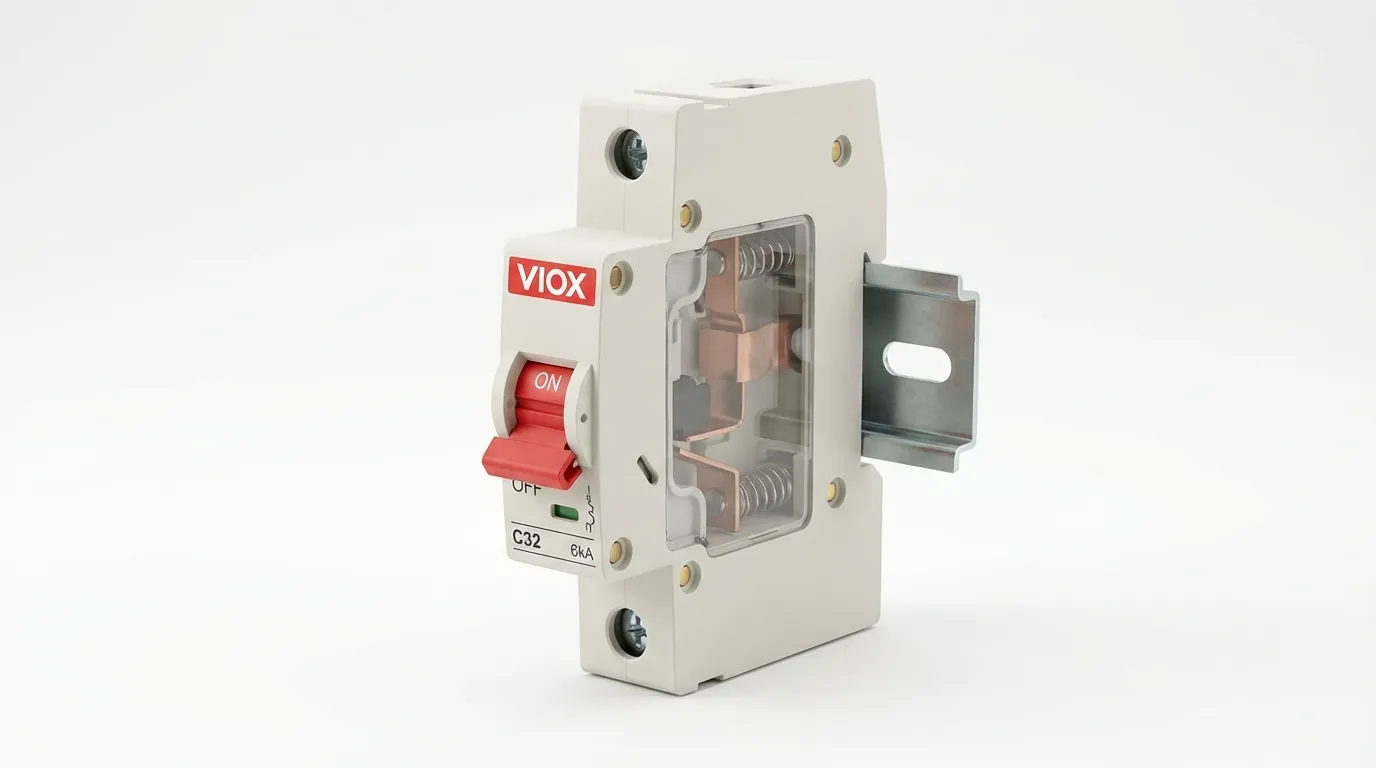
A Miniature Circuit Breaker (MCB) is a compact, automatically operated electrical switch designed to protect low-voltage circuits from overcurrent and short-circuit conditions. MCBs replaced traditional fuses in residential and light commercial applications due to their reusability and faster response times.
MCB Core Characteristics
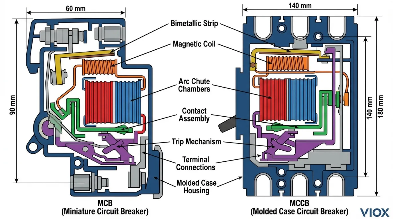
MCBs operate using a thermal-magnetic trip mechanism combining two protection methods. The thermal element uses a bimetallic strip that bends under prolonged overload conditions, while the magnetic element responds instantly to short-circuit currents using an electromagnetic coil.
Technical specifications of standard MCBs:
- Current Rating: 0.5A to 125A (most common: 6A, 10A, 16A, 20A, 32A, 63A)
- Breaking Capacity: 3kA, 6kA, 10kA, or 15kA depending on application
- Voltage Rating: 230V AC (single-phase) or 400V AC (three-phase)
- Trip Curves: Type B (3-5×In), Type C (5-10×In), Type D (10-20×In)
- Pole Configuration: 1P, 2P, 3P, 4P options
- Response Time: 0.01-0.1 seconds for short circuits
- Standards Compliance: IEC 60898-1, EN 60898-1
MCBs excel in residential applications where simplicity, compact size, and cost-effectiveness are priorities. Their fixed trip characteristics make them ideal for predictable loads like lighting circuits, receptacles, and small appliances.
Understanding MCCB: Molded Case Circuit Breaker Fundamentals
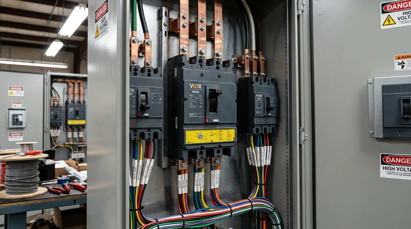
A Molded Case Circuit Breaker (MCCB) is an industrial-grade electrical protection device housed in a robust molded insulating case, designed to interrupt circuits during overcurrent, short-circuit, and ground fault conditions. The “molded case” refers to the thermoset composite or glass polyester housing that provides superior mechanical strength and environmental protection.
MCCB Core Characteristics
MCCBs employ either thermal-magnetic trip units (traditional) or electronic trip units (modern) for precise protection. Electronic trip units offer programmable settings, ground fault protection, and communication capabilities for smart grid integration.
Technical specifications of standard MCCBs:
- Current Rating: 10A to 2,500A (common ranges: 63A, 100A, 250A, 400A, 630A, 800A)
- Breaking Capacity: 10kA to 200kA (Icu rating per IEC 60947-2)
- Voltage Rating: Up to 1,000V AC (690V most common for industrial)
- Trip Unit Types: Thermal-magnetic (TM), electronic (ETU), microprocessor-based
- Adjustability: Overload (0.4-1×In), short-circuit delay, instantaneous trip
- Pole Configuration: 2P, 3P, 4P with various neutral arrangements
- Standards Compliance: IEC 60947-2, UL 489, GB 14048.2
MCCBs dominate industrial and commercial applications requiring high current capacity, adjustable protection coordination, and robust construction for harsh environments.
MCCB vs MCB: Comprehensive Technical Comparison
1. Current Rating and Load Capacity
The most fundamental difference between MCCB and MCB lies in their current-handling capabilities, which directly determines their application scope.
MCB Current Ratings:
- Residential circuits: 6A-63A (lighting, outlets, small appliances)
- Light commercial: 32A-125A (small HVAC units, commercial equipment)
- Maximum continuous current: 125A
MCCB Current Ratings:
- Light industrial: 63A-250A (motor feeders, small machinery)
- Heavy industrial: 400A-1,600A (main distribution, large motors)
- Specialized applications: Up to 2,500A (service entrance, transformer protection)
This capacity difference means MCCBs can protect entire building electrical systems, while MCBs protect individual branch circuits. For example, a 200A MCCB might serve as the main breaker for a commercial building, with 20A MCBs protecting individual office circuits downstream.
2. Breaking Capacity (Interrupting Rating)
Breaking capacity represents the maximum fault current a breaker can safely interrupt without damage. This critical specification must exceed the prospective short-circuit current at the installation point.
MCB Breaking Capacities:
- Domestic installations: 6kA (6,000A fault current)
- Commercial buildings: 10kA standard
- Industrial feeders: 15kA maximum
MCCB Breaking Capacities:
- Light industrial: 25kA-50kA
- Heavy industrial: 65kA-100kA
- Critical infrastructure: 150kA-200kA (specialized units)
Higher breaking capacity in MCCBs enables installation closer to power sources where fault currents are highest, such as main service entrances and transformer secondary connections.
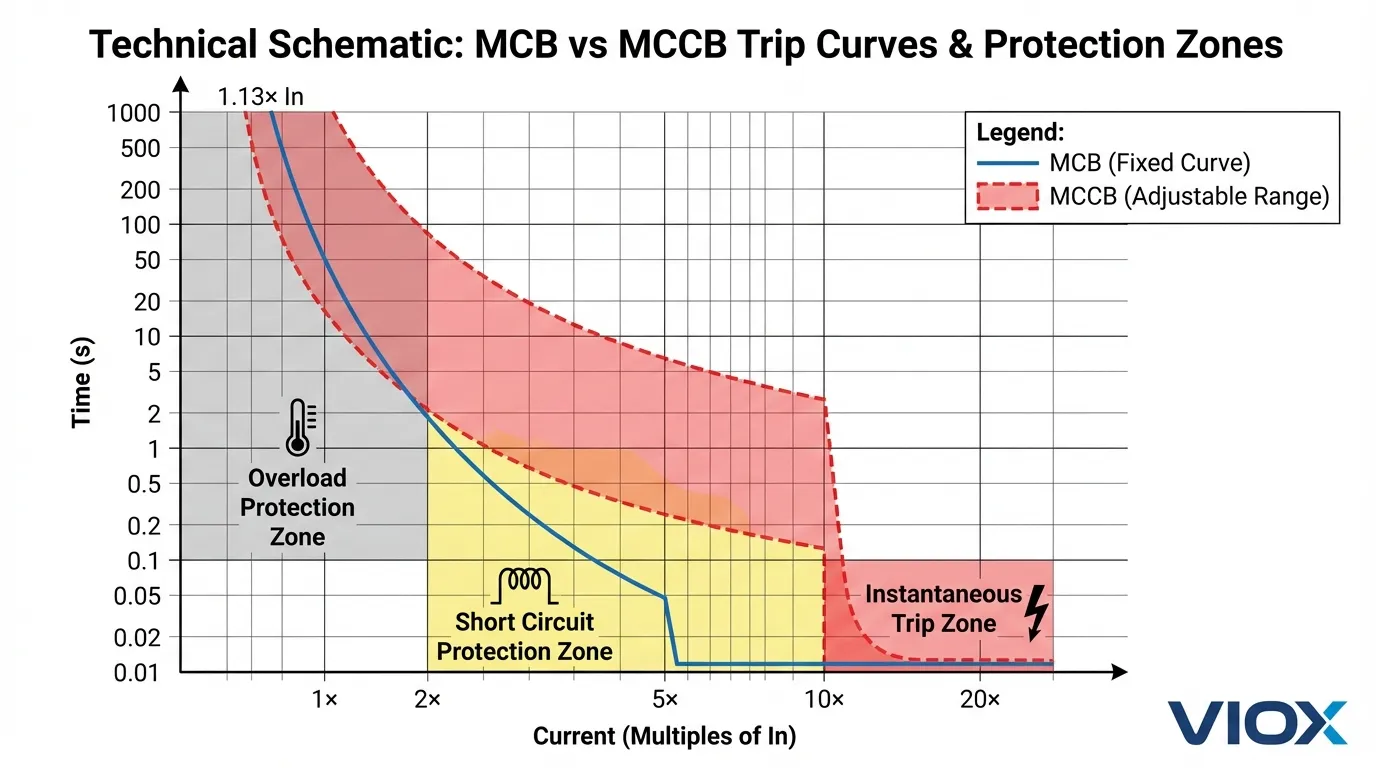
3. Trip Setting Adjustability
Trip setting flexibility represents a major operational difference affecting protection coordination and system selectivity.
MCB Trip Settings (Fixed):
- Factory-set trip curves (B, C, or D type)
- No field adjustment possible
- Overload protection: Fixed at rated current
- Magnetic trip: Fixed at 3-20× rated current (curve dependent)
- Advantage: Simplicity, no configuration errors
- Limitation: Cannot adapt to changing load conditions
MCCB Trip Settings (Adjustable):
- Thermal overload: Adjustable 0.4-1.0× rated current
- Short-circuit delay: Adjustable time bands (I²t curves)
- Instantaneous trip: Adjustable 2-15× rated current
- Ground fault: Optional, adjustable sensitivity and delay
- Advantage: Precise coordination, load-specific optimization
- Requirement: Proper configuration by qualified personnel
This adjustability allows MCCBs to achieve selective coordination, where only the breaker closest to a fault trips, maintaining power to unaffected circuits—critical for hospitals, data centers, and continuous process industries.
4. Physical Size and Installation Requirements
MCB Dimensions:
- Width: 17.5mm-18mm per pole (DIN rail standard)
- Height: 85mm typical
- Depth: 70-80mm
- Weight: 100-200g per pole
- Mounting: DIN rail (35mm TH35-7.5 or TH35-15)
- Panel space: Minimal, high-density installation possible
MCCB Dimensions:
- Width: 70mm-280mm (frame size dependent)
- Height: 140mm-320mm
- Depth: 80mm-150mm
- Weight: 1-15kg depending on frame size
- Mounting: Panel mounting with bolts, busbar connections
- Panel space: Requires dedicated compartment with clearance
The size difference impacts panel design significantly. A typical residential panel accommodates 12-40 MCB positions in compact space, while an industrial MCC (Motor Control Center) dedicates substantial volume to each MCCB with proper heat dissipation spacing.
5. Cost Analysis and Economic Considerations
MCB Pricing Structure:
- Basic single-pole: $5-15
- Three-phase (3P): $25-60
- High breaking capacity (10kA): $30-100
- Installation cost: Minimal (DIN rail snap-on)
- Replacement philosophy: Dispose and replace entire unit
MCCB Pricing Structure:
- Entry-level (63-100A): $100-300
- Mid-range (250-400A): $400-1,200
- High-capacity (630-1,600A): $1,500-5,000+
- Electronic trip units: Add $500-2,000
- Installation cost: Higher (requires skilled electrician, torque specifications)
- Maintenance philosophy: Serviceable components, periodic testing
Total Cost of Ownership (TCO) Considerations:
While MCCBs cost significantly more upfront, their adjustability and serviceability often result in lower TCO for industrial applications. MCCBs reduce nuisance tripping through proper coordination, minimize downtime, and provide monitoring capabilities that identify issues before failures occur.
6. Protection Features and Capabilities
MCB Protection Functions:
- Overload protection (thermal element)
- Short-circuit protection (magnetic element)
- Basic arc fault protection (inherent)
- No ground fault protection (requires separate RCCB)
- No communication capabilities
- No monitoring or diagnostics
MCCB Protection Functions:
- Overload protection (adjustable thermal or electronic)
- Short-circuit protection (adjustable magnetic or electronic)
- Ground fault protection (optional, adjustable)
- Undervoltage release (optional accessory)
- Shunt trip (remote tripping capability)
- Zone selective interlocking (ZSI)
- Power monitoring (electronic units)
- Communication protocols (Modbus, Profibus, Ethernet/IP)
- Predictive maintenance alerts
- Event logging and fault diagnostics
Advanced MCCBs with electronic trip units function as intelligent protection devices, providing real-time data on current, voltage, power factor, energy consumption, and harmonic distortion—capabilities impossible with basic MCBs.
Detailed Comparison Table: MCCB vs MCB
| Parameter | MCB (Miniature Circuit Breaker) | MCCB (Molded Case Circuit Breaker) |
|---|---|---|
| Current Rating | 0.5A – 125A | 10A – 2,500A |
| Breaking Capacity | 3kA – 15kA | 10kA – 200kA |
| Voltage Rating | 230V – 400V AC | Up to 1,000V AC |
| Trip Adjustment | Fixed (factory set) | Adjustable (field configurable) |
| Trip Curve Types | B, C, D (fixed) | Customizable I²t curves |
| Pole Configuration | 1P, 2P, 3P, 4P | 2P, 3P, 4P |
| Physical Size | 17.5mm per pole | 70mm – 280mm per unit |
| Weight | 100-200g | 1-15kg |
| Mounting Method | DIN rail snap-on | Panel bolt-on, busbar |
| Installation Time | 1-2 minutes | 15-60 minutes |
| Price Range | $5 – $100 | $100 – $5,000+ |
| Trip Mechanism | Thermal-magnetic (fixed) | Thermal-magnetic or electronic |
| Ground Fault Protection | No (requires RCCB) | Optional (integrated) |
| Remote Control | No | Yes (shunt trip, motor operator) |
| Communication | No | Yes (electronic units) |
| Monitoring Capability | No | Yes (current, voltage, power, energy) |
| Selectivity | Limited | Full coordination possible |
| Maintenance | Replace when faulty | Serviceable, testable |
| Service Life | 10-15 years | 20-30 years |
| Standards | IEC 60898-1, EN 60898 | IEC 60947-2, UL 489 |
| Typical Applications | Residential, light commercial | Industrial, commercial mains |
| Arc Interruption | Basic arc chutes | Advanced arc extinction chambers |
| Ambient Temperature | -5°C to +40°C | -25°C to +70°C (varies) |
| Altitude Rating | Up to 2,000m standard | Up to 2,000m (derating above) |
| Accessories | Minimal (auxiliary contacts) | Extensive (UVR, shunt trip, motor operator) |
Application Selection Guide: When to Use MCB vs MCCB
Choose MCB When:
Residential Applications:
- Lighting circuits (6A-16A MCBs)
- General power outlets (16A-20A MCBs)
- Kitchen appliances (20A-32A MCBs)
- Air conditioning units up to 5 tons (32A-40A MCBs)
- Water heaters and small pumps (20A-32A MCBs)
Light Commercial Applications:
- Office lighting and receptacles
- Small retail stores
- Restaurant equipment (individual circuits)
- Small workshops
- Residential apartment buildings (individual units)
Key Selection Criteria for MCB:
- Total circuit current ≤ 125A
- Prospective fault current ≤ 15kA
- Fixed protection adequate for stable loads
- Space constraints require compact solution
- Budget-conscious projects
- Simple installation and maintenance preferred
Choose MCCB When:
Industrial Applications:
- Motor feeders for equipment >10HP
- Main distribution panels
- Transformer secondary protection
- Welding equipment and heavy machinery
- Industrial HVAC systems (chillers, cooling towers)
- Conveyor systems and production lines
Commercial Applications:
- Building main service entrance
- Floor distribution panels
- Elevator and escalator feeders
- Commercial kitchen main feeders
- Data center power distribution
- Hospital critical power systems
Critical Infrastructure:
- Wastewater treatment plants
- Manufacturing facilities
- Telecommunications facilities
- Emergency power systems
- Renewable energy installations (solar, wind)
Key Selection Criteria for MCCB:
- Circuit current >125A or future expansion anticipated
- Prospective fault current >15kA
- Selective coordination required
- Adjustable protection needed for varying loads
- Monitoring and communication capabilities desired
- Harsh environmental conditions
- Critical applications requiring maximum reliability
Installation and Wiring Differences
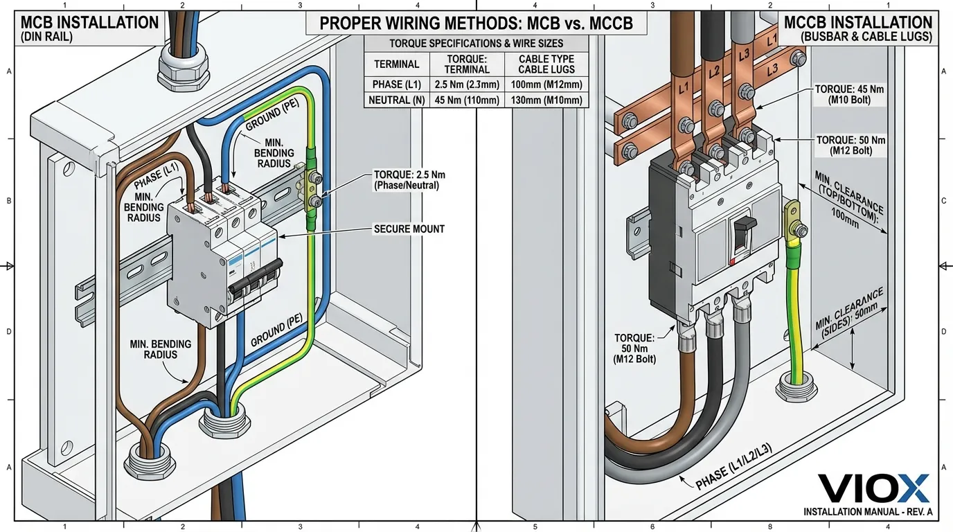
MCB Installation Best Practices
DIN Rail Mounting:
- Snap MCB onto 35mm DIN rail (TH35-7.5 standard)
- Ensure secure mechanical engagement
- Maintain minimum 5mm spacing between adjacent MCBs for heat dissipation
- Group by circuit type for logical organization
Wiring Connections:
- Conductor size: 1.5mm² – 16mm² (14-6 AWG)
- Terminal torque: 2-3 Nm (check manufacturer specifications)
- Connection method: Screw terminals (most common) or plug-in connectors
- Busbar connection: Use MCB-rated busbars for multiple device linking
- Wire preparation: Strip 10-12mm insulation, no ferrules required for solid conductors
Panel Layout Considerations:
- Install with toggle switch accessible from front
- Maintain NEC/IEC required working clearances
- Label each circuit clearly
- Consider future expansion space
MCCB Installation Best Practices
Panel Mounting:
- Mark and drill mounting holes per manufacturer template
- Use appropriate bolt size (typically M8-M12)
- Torque mounting bolts to specification (typically 10-25 Nm)
- Ensure panel back plate provides adequate support for MCCB weight
Wiring Connections:
- Conductor size: 10mm² – 300mm² (8 AWG – 600 kcmil) depending on frame size
- Use cable lugs crimped to manufacturer specifications
- Terminal torque: Critical—follow exact specifications (typically 25-100 Nm)
- Busbar connection: Use appropriately rated busbars with proper support
- Phase sequence: Maintain consistent L1-L2-L3 arrangement
- Neutral handling: 4-pole MCCBs provide switched neutral where required
Critical Installation Requirements:
- Verify adequate ventilation around MCCB
- Maintain minimum clearances per NEC 110.26 or local codes
- Use anti-vibration mounting in mobile or high-vibration applications
- Configure trip settings before energization
- Perform insulation resistance testing before commissioning
- Document settings and maintain as-built records
Maintenance and Testing Requirements
MCB Maintenance (Minimal)
Routine Inspection (Annual):
- Visual inspection for physical damage, discoloration, or burning
- Check for loose connections (thermal imaging recommended)
- Verify proper mechanical operation (manual trip test)
- Clean dust and debris from panel
Functional Testing (Every 3-5 Years):
- Manual operation test (trip and reset)
- Test button verification (if equipped)
- Insulation resistance measurement
- Contact resistance measurement (if accessible)
Replacement Indicators:
- Visible damage or burning
- Frequent nuisance tripping
- Failure to trip under test conditions
- Age >15 years in critical applications
- Contact welding or mechanical binding
Important Note: MCBs are sealed units with no user-serviceable parts. Replace entire device when faulty—do not attempt repairs.
MCCB Maintenance (Comprehensive)
Routine Inspection (Quarterly to Annual):
- Visual inspection for damage, corrosion, discoloration
- Thermal imaging of connections under load
- Verify trip unit settings match documentation
- Check auxiliary device operation
- Clean arc chutes and ventilation paths
- Inspect busbar connections for tightness
Functional Testing (Annual to Triennial):
- Manual operation test (open/close cycling)
- Primary injection testing (trip time verification)
- Insulation resistance testing (>1000V megger)
- Contact resistance measurement
- Ground fault function testing (if equipped)
- Communication interface verification (electronic units)
Comprehensive Testing (Every 5-10 Years):
- Complete trip unit calibration
- Contact wear assessment
- Arc chute inspection and replacement if needed
- Mechanical component lubrication
- Firmware updates (electronic units)
- Full functional testing per manufacturer procedures
Maintenance Records:
Maintain detailed records including:
- Installation date and initial settings
- All testing dates and results
- Any adjustments or repairs performed
- Fault history and trip events
- Replacement of components or accessories
Common Selection Mistakes and How to Avoid Them
Mistake 1: Undersizing Breaking Capacity
Problem: Installing a 6kA MCB where prospective fault current is 12kA creates catastrophic failure risk. The breaker may explode when attempting to interrupt fault current beyond its rating.
Solution: Calculate prospective short-circuit current at installation point using utility transformer data and conductor impedances. Select breaker with breaking capacity ≥125% of calculated fault current. When uncertain, specify higher breaking capacity (10kA MCBs cost only marginally more than 6kA versions).
Mistake 2: Using MCB for High-Current Applications
Problem: Paralleling multiple MCBs to achieve higher current capacity (e.g., two 63A MCBs for 126A load) violates electrical codes and creates safety hazards due to unequal current sharing.
Solution: Use appropriately rated MCCB for any continuous load >100A. Never parallel circuit breakers unless specifically designed and approved for parallel operation.
Mistake 3: Ignoring Coordination Requirements
Problem: Installing MCBs throughout a system without considering selective coordination results in upstream breakers tripping for downstream faults, causing unnecessary outages to unaffected circuits.
Solution: Perform coordination study using manufacturer time-current curves. Use MCCBs with adjustable settings at upstream positions to achieve selectivity with downstream MCBs. Specify electronic trip MCCBs for critical applications requiring guaranteed coordination.
Mistake 4: Incorrect Trip Curve Selection
Problem: Using Type B MCBs (3-5×In magnetic trip) for motor circuits causes nuisance tripping during motor starting, while using Type D MCBs (10-20×In) for lighting circuits provides inadequate short-circuit protection.
Solution: Match trip curve to load characteristics:
- Type B: Lighting, resistive loads, long cable runs
- Type C: General purpose, small motors, transformers (most common)
- Type D: Large motors, transformers, high inrush loads
Mistake 5: Neglecting Environmental Factors
Problem: Installing standard MCBs rated for 40°C ambient in enclosed panels where temperature exceeds 50°C causes premature tripping and reduced service life.
Solution: Apply derating factors for high ambient temperature and enclosed spaces. Consider MCCBs with higher temperature ratings for harsh environments. Ensure adequate panel ventilation or specify breakers with extended temperature ratings.
Mistake 6: Overlooking Future Expansion
Problem: Fully loading panel capacity with MCBs leaves no room for future circuit additions, requiring costly panel replacement.
Solution: Design panels with 20-30% spare capacity. Use MCCBs for main feeders with ratings allowing future load growth. Consider modular panel systems enabling easy expansion.
Standards and Certifications: Ensuring Compliance
International Standards
IEC 60898-1 (MCB Standard):
- Defines performance requirements for MCBs ≤125A
- Specifies trip curve characteristics (B, C, D types)
- Establishes breaking capacity ratings (Icn)
- Mandates marking and labeling requirements
- Covers mechanical and electrical endurance testing
IEC 60947-2 (MCCB Standard):
- Covers MCCBs and circuit breakers in general
- Defines Icu (ultimate breaking capacity) and Ics (service breaking capacity)
- Specifies utilization categories (A and B)
- Establishes coordination requirements (Type 1 and Type 2)
- Includes requirements for electronic trip units
UL 489 (North American Standard):
- Covers molded-case circuit breakers and switches
- Defines interrupting ratings (AIR – Ampere Interrupting Rating)
- Specifies 80% vs 100% rated breakers
- Establishes testing procedures for North American market
- Required for UL-listed products in USA/Canada
Critical Certifications to Verify
For MCBs:
- CE marking (European conformity)
- CB certificate (international mutual recognition)
- UL listing (North American markets)
- CCC certification (China market)
- Local authority approvals (varies by jurisdiction)
For MCCBs:
- All MCB certifications plus:
- Type testing reports from accredited laboratories
- Short-circuit coordination studies
- Seismic qualification (critical infrastructure)
- Marine certifications (shipboard applications)
- Hazardous location approvals (ATEX, IECEx for explosive atmospheres)
Compliance Verification Checklist
Before purchasing MCBs or MCCBs, verify:
- Appropriate standard compliance for your jurisdiction
- Breaking capacity certification at rated voltage
- Temperature rating suitable for installation environment
- Coordination documentation if selective operation required
- Manufacturer test reports available for inspection
- Warranty coverage and technical support availability
- Spare parts availability for MCCBs requiring maintenance
Future Trends: Smart Circuit Breakers and IoT Integration
Digital Transformation in Circuit Protection
Modern MCCBs increasingly incorporate smart technology transforming them from passive protection devices into active power management tools:
Current Capabilities:
- Real-time monitoring of current, voltage, power, energy
- Harmonic analysis and power quality assessment
- Predictive maintenance alerts based on operating conditions
- Remote control and status monitoring
- Integration with building management systems (BMS)
- Cloud connectivity for analytics and reporting
Emerging Technologies:
- AI-powered fault prediction and diagnostics
- Blockchain-based maintenance verification
- Digital twin modeling for system optimization
- Cybersecurity features for critical infrastructure protection
- Self-healing grid integration capabilities
Smart MCBs: Bridging the Gap
While traditional MCBs lack intelligence, new smart MCB products are emerging:
- Wi-Fi or Bluetooth connectivity for residential monitoring
- Energy consumption tracking per circuit
- Smartphone app control and notifications
- Integration with home automation systems
- Overcurrent event logging and analysis
These devices bridge the gap between basic MCB protection and MCCB intelligence at residential price points, representing the future of home electrical safety.
Frequently Asked Questions (FAQ)
General Questions
Q: Can I replace an MCB with an MCCB in my residential panel?
A: Physically, no—MCCBs are too large for residential panels designed for DIN-rail MCBs. Functionally, it’s also unnecessary and cost-prohibitive. MCCBs are designed for industrial applications. If you need higher capacity than MCBs provide, consider upgrading your entire panel to a larger service with appropriate main breaker.
Q: How do I know if I need MCB or MCCB for my application?
A: Use this simple decision tree:
- Load current ≤100A + residential/light commercial = MCB
- Load current >100A + industrial/commercial = MCCB
- Adjustable protection needed = MCCB
- Selective coordination required = MCCB
- Budget-conscious + simple loads = MCB
Q: What does the “C” in C32 MCB mean?
A: The “C” indicates the trip curve type (magnetic trip threshold), while “32” is the rated current in amperes. Type C MCBs trip magnetically at 5-10× rated current, making them suitable for general-purpose circuits with moderate inrush currents. Type B trips at 3-5×In (sensitive, for lighting), Type D at 10-20×In (motors, transformers).
Technical Questions
Q: Can MCCBs protect against ground faults?
A: Some MCCBs include optional ground fault protection modules (GFPM) that detect earth leakage currents. This feature is not standard but available as an add-on or integrated function in electronic trip units. Standard MCBs do not provide ground fault protection—you need a separate RCCB (Residual Current Circuit Breaker) for that function.
Q: What is the difference between Icu and Ics ratings on MCCBs?
A: Icu (Ultimate Breaking Capacity) is the maximum fault current the MCCB can interrupt once without damage, but may not be suitable for continued service. Ics (Service Breaking Capacity) is the fault current level the MCCB can interrupt multiple times and remain in service. For critical applications, ensure Ics meets or exceeds prospective fault current. Typically, Ics = 50-100% of Icu depending on breaker class.
Q: How often should MCBs and MCCBs be replaced?
A: MCBs: Replace every 10-15 years as preventive maintenance, or immediately if they show signs of damage, frequent tripping, or failure to trip during testing. MCCBs: With proper maintenance, MCCBs can last 20-30 years. Replace based on condition assessment, fault interruption history, and manufacturer recommendations. MCCBs that have interrupted major faults should be inspected and possibly replaced even if they appear functional.
Installation Questions
Q: Can I install MCBs or MCCBs in any orientation?
A: MCBs are typically designed for vertical mounting with terminals up/down, but many can be mounted horizontally without derating. MCCBs can usually be mounted in various orientations, but this may affect current rating due to heat dissipation changes. Always consult manufacturer installation instructions and apply derating factors if specified for non-standard orientations.
Q: Do I need special tools to install MCCBs?
A: Yes. MCCB installation requires:
- Torque wrench (critical for proper terminal tightening)
- Cable lug crimping tools
- Insulation resistance tester (megger)
- Multimeter for verification
- Thermal imaging camera (recommended for commissioning)
- Trip unit programming tools (for electronic units)
MCB installation requires only basic electrician tools (screwdrivers, wire strippers, multimeter).
Cost and Maintenance Questions
Q: Why are MCCBs so much more expensive than MCBs?
A: MCCBs cost more due to:
- Higher current and breaking capacity requiring more robust materials
- Precision adjustable trip mechanisms
- Extensive testing and certification requirements
- Optional features (ground fault, communication, monitoring)
- Serviceable design with replaceable components
- Lower production volumes compared to mass-produced MCBs
The price difference reflects the industrial-grade construction and advanced capabilities required for critical applications.
Q: Can I test MCBs and MCCBs myself?
A: MCBs: Basic manual operation testing (trip and reset) can be performed by homeowners. However, proper trip time and current threshold testing requires specialized equipment and should be performed by qualified electricians.
MCCBs: Testing should only be performed by qualified electrical technicians with appropriate test equipment (primary injection test sets, insulation testers). Improper testing can damage the breaker or create safety hazards. Many jurisdictions require licensed electricians for MCCB testing and maintenance.
Conclusion: Making the Right Choice for Your Application
Selecting between MCCB and MCB fundamentally depends on your application requirements, load characteristics, and system design objectives. This comprehensive comparison reveals that these devices, while serving the same basic function of circuit protection, are optimized for distinctly different applications.
Choose MCBs for residential and light commercial applications where:
- Circuit currents remain below 125A
- Fixed protection characteristics suit stable loads
- Compact size and economical pricing are priorities
- Simple installation and minimal maintenance are desired
- Prospective fault currents don’t exceed 15kA
Choose MCCBs for industrial and commercial applications requiring:
- Current capacity from 100A to 2,500A
- Adjustable protection for coordination and selectivity
- High breaking capacity (10kA-200kA) near power sources
- Monitoring, communication, and smart grid integration
- Robust construction for harsh environments
- Long service life with maintainable components
Key Success Factors:
- Perform proper load calculations including future expansion
- Calculate prospective fault currents at installation points
- Consider coordination requirements for system reliability
- Verify environmental conditions and apply appropriate derating
- Ensure compliance with applicable standards and codes
- Select reputable manufacturers with proven track records
- Plan for maintenance and testing throughout service life
The electrical protection landscape continues evolving with smart technology integration, but the fundamental principles remain: match the protection device to the application, prioritize safety over cost savings, and design systems with future needs in mind.
For complex installations or critical applications, consult with qualified electrical engineers to perform detailed coordination studies and ensure optimal protection device selection. The investment in proper design and quality components pays dividends through enhanced safety, reliability, and reduced lifecycle costs.
Related Resources:
