On this page
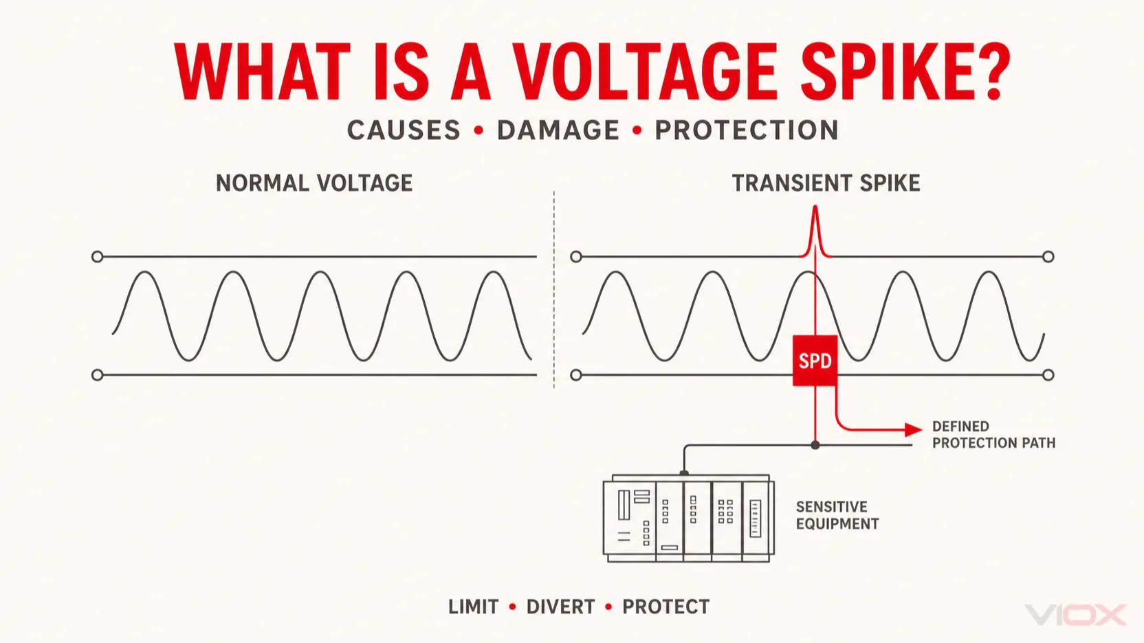
A voltage spike is a rapid, short-duration rise above the normal voltage of an electrical circuit. It is a type of transient overvoltage commonly caused by lightning influence, utility switching, fault clearing, or the interruption of inductive loads such as motors, transformers, relays, and contactor coils.
A surge protective device (SPD) can limit many transient overvoltages by diverting surge current through a defined protection path. However, an SPD does not correct sustained high voltage, undervoltage, overload, poor voltage regulation, or every form of electrical noise. Correct protection begins by identifying the disturbance.
Voltage Spike Meaning
In power-quality work, a voltage spike is a steep, temporary departure from the normal voltage waveform. Depending on the source and circuit, it may be an impulsive transient with a single sharp peak or an oscillatory transient that rings before decaying.
The term power surge is often used broadly in everyday language. Engineers usually need more precision because the duration, waveform, source impedance, available energy, and protection path determine whether an SPD, voltage relay, filter, snubber, uninterruptible power supply (UPS), or another measure is appropriate.
Voltage Spike vs Surge, Swell, Sag, and Inrush Current
These disturbances can produce similar complaints—equipment resets, flickering lights, alarms, or failed electronics—but they are not the same problem.
| Disturbance | What changes | Typical behavior | Appropriate first response |
|---|---|---|---|
| Voltage spike / transient overvoltage | Voltage rises sharply | Very short, steep-fronted event | Identify the source; apply coordinated SPD or source suppression |
| Voltage swell | RMS voltage rises | Lasts longer than a fast transient | Investigate supply regulation, load switching, and system conditions |
| Sustained overvoltage | Supply remains above its intended range | Persists rather than decaying rapidly | Use voltage monitoring or disconnection appropriate to the system; correct the supply fault |
| Voltage sag or dip | RMS voltage falls | Temporary reduction | Check source capacity, faults, conductor voltage drop, and large-load starting |
| Inrush current | Load current rises at energization | Common with motors, transformers, and capacitive inputs | Review starting method, circuit impedance, and overcurrent-device coordination |
| Electrical noise | Unwanted high-frequency content | May be repetitive or continuous | Investigate coupling, shielding, grounding, filtering, and cable routing |
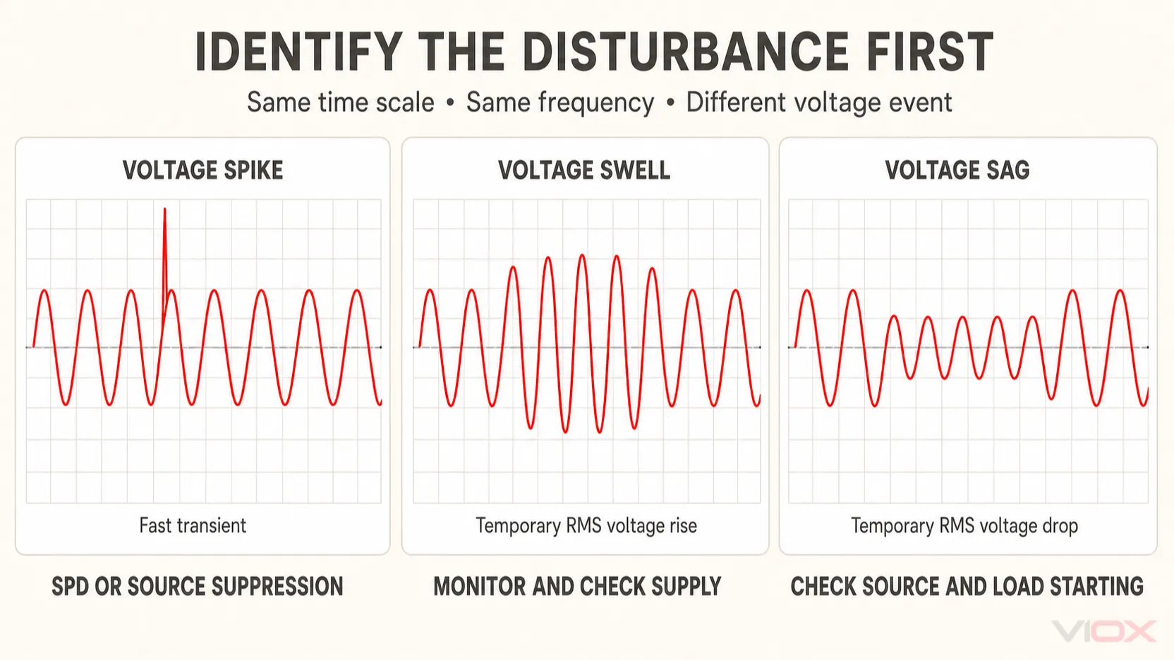
This distinction prevents a common specification error: installing a larger SPD for a problem that is actually sustained overvoltage, voltage sag, or excessive starting current.
What Causes Voltage Spikes?
Lightning and induced transients
A direct strike is not required for lightning activity to produce a transient inside an installation. Electromagnetic coupling, nearby conductors, incoming power lines, and communication cables can carry surge energy into a building or industrial system.
Lightning-related protection is a system-level task. It can involve an external lightning protection system, equipotential bonding, earthing, coordinated SPDs, and protection on power and signal conductors. One plug-in protector should not be treated as complete lightning protection.
Utility and distribution switching
Capacitor-bank switching, transformer energization, fault clearing, reclosing, and other network operations can create transient voltage changes. The waveform that reaches a load depends on the distribution network, installation impedance, and protective devices between the source and the equipment.
Switching inductive loads
Motors, solenoids, transformers, relays, and contactor coils store energy in a magnetic field. When current is interrupted, the collapsing field can generate a high voltage across the switching device or coil. The basic relationship is:
v = L × di/dtThe faster the current changes, the greater the induced voltage can become for a given inductance. This is why a small contactor coil can create a troublesome local transient even when it is not a large load.
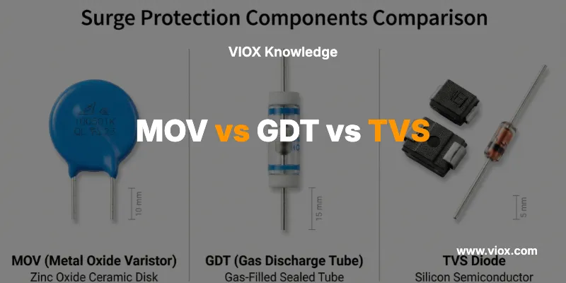
Source suppression may be more effective than relying only on a panel SPD. Depending on whether the coil is AC or DC and how quickly it must release, the solution may involve a flyback diode, resistor-capacitor snubber, metal-oxide varistor (MOV), transient-voltage-suppression (TVS) diode, or manufacturer-approved suppression module.
Wiring, faults, and equipment operation
Loose or intermittent connections, arcing contacts, abrupt fault interruption, power-electronic switching, and incorrect wiring can also create or propagate transients. A spike is therefore a symptom to characterize—not proof that lightning or the utility is responsible.
How Voltage Spikes Damage Equipment
A transient can exceed the insulation strength or component withstand capability of the affected circuit. The result depends on peak voltage, current path, source impedance, duration, repetition, and the susceptibility of the connected equipment.
Possible effects include:
- semiconductor junction breakdown;
- punctured or weakened insulation;
- damaged power supplies, control boards, drivers, and communication ports;
- relay, programmable logic controller (PLC), sensor, or drive resets;
- corrupted signals and unexplained control-system faults;
- gradual degradation that contributes to a later failure.
The absence of immediate failure does not prove that no stress occurred. Repetitive transients can reduce the remaining margin of insulation or protective components without leaving an obvious external mark.
How to Prevent Voltage Spikes from Damaging Equipment
Effective protection is layered. Each layer addresses a different path or source.
| Protection layer | Main purpose | Important boundary |
|---|---|---|
| Source suppression | Limits a transient close to a relay, coil, motor control, or switching device | Suppressor type must match AC/DC operation, release time, voltage, and manufacturer instructions |
| Service-entrance protection | Manages incoming surge energy at the installation boundary | Selection depends on supply system, lightning exposure, local rules, and product rating |
| Distribution-panel protection | Limits residual and internally generated transients closer to downstream circuits | Coordination and installation conductor layout affect the voltage seen by equipment |
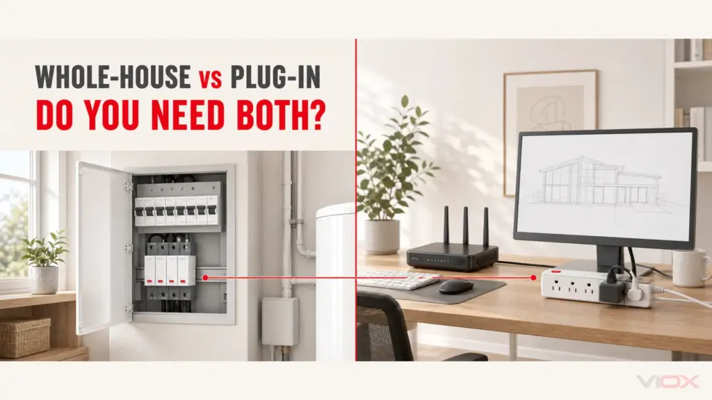
| Equipment-level protection | Provides final-stage protection near sensitive loads | Must be compatible with the upstream protection and equipment interface |
| Signal and communication protection | Addresses transients entering through data, control, antenna, or communication conductors | Power-only protection leaves another entry path unprotected |
| Bonding, earthing, and wiring | Provides a controlled, low-impedance surge-current path and reduces damaging potential differences | An SPD cannot compensate for incorrect bonding, long loops, or an unsuitable protection mode |
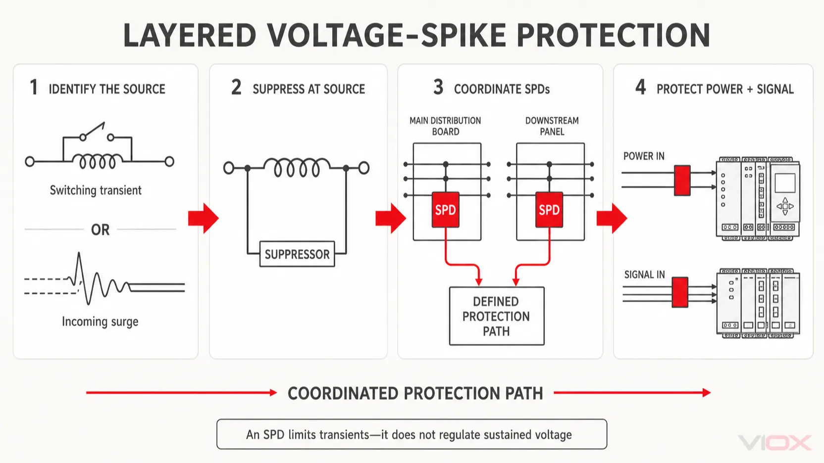
Use coordinated SPDs—not one device in isolation
For low-voltage installations, Type 1, Type 2, and Type 3 SPDs have different installation roles and test duties. They may be coordinated from the service entrance through distribution boards to sensitive equipment when the system design requires it. See the VIOX guide to Type 1, Type 2, and Type 3 SPDs for the location and duty of each type.
An SPD should be selected by more than the largest kA value on its label. Relevant checks include:
- AC or DC system and nominal system voltage;
- maximum continuous operating voltage, shown as Uc in IEC practice or MCOV in North American practice;
- required protection mode for the earthing or grounding arrangement;
- voltage protection level (Up) or the applicable listed let-through/protection rating;
- Type 1, Type 2, Type 3, or combined duty as required by the installation point;
- discharge-current and impulse-current ratings relevant to that SPD type;
- prospective short-circuit conditions, upstream protection, and manufacturer instructions;
- status indication, remote signaling, and replaceable-module requirements;
- conductor routing and connection length.
For a complete explanation of these parameters, use the VIOX SPD working principle and selection guide rather than turning this definition page into a second SPD buying guide.
Keep the protection path short and direct
An SPD limits the voltage at its terminals, but the installation conductors add voltage during a rapidly changing surge current. Long, looped, or poorly routed connections can therefore increase the residual voltage presented to downstream equipment.
Installers should follow the device instructions and applicable rules for conductor routing, overcurrent protection, earthing arrangement, and separation. The VIOX guide to common SPD installation mistakes explains why lead length and wiring configuration matter.
Do not use an SPD for sustained overvoltage
An SPD is designed to limit transient overvoltage. It is not a voltage regulator and should not be expected to correct a persistent high supply voltage, lost-neutral condition, incorrect transformer tap, or other sustained abnormal condition.
Those faults require diagnosis and an appropriate monitoring, control, or disconnection strategy. Likewise, a miniature circuit breaker or molded-case circuit breaker protects against overcurrent within its characteristics; it is not a substitute for transient overvoltage protection.
How to Detect a Voltage Spike
A standard digital multimeter may show normal voltage while missing a fast transient. Investigation may require a power-quality analyzer, oscilloscope, or transient recorder with sufficient bandwidth, sampling capability, triggering, voltage range, and measurement category for the circuit.
A useful diagnostic sequence is:
- Record the affected equipment, time, operating state, and alarm or failure symptom.
- Check whether the event coincides with motor, contactor, capacitor-bank, generator, transfer-switch, or utility operations.
- Determine whether the disturbance is present on the power conductors, control wiring, or communication lines.
- Capture the waveform with equipment and probes rated for the installation category and expected voltage.
- Compare the event timing and waveform with switching operations before selecting suppression.
- Verify the proposed solution under the same operating condition without exceeding equipment or personnel safety limits.
Measurement on energized distribution systems should be performed only by qualified personnel using appropriately rated instruments and safe work practices. A transient problem should not be diagnosed by connecting an unsuitable oscilloscope or grounded probe directly to a hazardous circuit.
Standards and Product Boundaries
IEC 61643-11:2025 covers requirements and test methods for SPDs connected to AC low-voltage power systems. It describes devices intended to limit surge voltage and divert surge current; it does not make every SPD suitable for every circuit or installation.
Different applications use different parts of the IEC 61643 series. Photovoltaic DC circuits, telecommunications and signaling networks, and other specialized systems require the applicable product standard and system-specific ratings. The VIOX overview of IEC 61643-11 for low-voltage SPDs explains this boundary in more detail.
For North American projects, verify the adopted electrical code, the SPD type and listing, manufacturer instructions, and applicable product requirements such as UL 1449. Do not assume that an IEC classification and a North American SPD type are interchangeable solely because the same number appears in both systems.
Voltage Spike Protection Checklist
Before specifying a solution, confirm:
- Is the event a fast transient, a longer swell, or sustained overvoltage?
- Is the likely source external, internal, or located at the affected load?
- Which conductors can carry the transient—power, PE/ground, signal, data, or antenna?
- Can the transient be suppressed at its source?
- Is coordinated protection needed at the service, panel, and equipment levels?
- Does the SPD match the AC/DC system, voltage, grounding arrangement, installation point, and short-circuit conditions?
- Are connection paths short and consistent with the manufacturer’s instructions?
- Is the protected equipment’s impulse withstand or interface requirement known?
- Is the selected measurement method capable of capturing the event safely?
Frequently Asked Questions
What is the difference between a voltage spike and a power surge?
The terms often overlap in everyday use. A voltage spike usually describes a very fast, short transient with a steep peak, while surge may be used more broadly for transient overvoltage events. For engineering decisions, use the measured waveform, duration, source, and energy rather than relying only on the label.
Can a circuit breaker protect against voltage spikes?
A conventional circuit breaker responds to overcurrent according to its trip characteristics. It does not normally operate fast enough or on the correct electrical quantity to serve as transient overvoltage protection. An SPD and a circuit breaker perform different functions and may both be required.
Can a UPS stop voltage spikes?
It depends on the UPS topology and its published surge-protection and power-conditioning characteristics. Do not assume that every UPS provides the same transient protection. Verify the manufacturer’s ratings and coordinate the UPS with upstream and equipment-level protection.
Does an SPD eliminate a voltage spike?
No. An SPD limits the transient voltage and diverts surge current through its designed protection path. The equipment still sees a residual voltage determined by the SPD characteristics, surge current, protection mode, and installation wiring.
When should an SPD be replaced?
Follow the status indicator, remote alarm, inspection results, manufacturer instructions, and site maintenance policy. Review the device after a severe electrical event or when there are signs of overheating, damage, or loss of protection status. A universal fixed replacement interval is not appropriate for every installation.
Technical References
- IEC 61643-11:2025 — Low-voltage surge protective devices connected to AC systems
- NIST — Surges Happen! How to Protect the Appliances in Your Home
- Fluke — Voltage sags, dips, swells, and transients
- UL Solutions — Overvoltage Protection
For project-specific SPD evaluation, compare the installation requirements with the published characteristics in the VIOX surge protective device range. Final selection and installation must follow the applicable local rules, system design, and device instructions.