
Quick Answer: How to Choose an MCB
To choose the right miniature circuit breaker (MCB), start with the circuit, not the breaker catalog. The MCB must protect the conductor, tolerate normal load and inrush current, interrupt the available fault current, and match the applicable installation standard.
The practical selection sequence is:
- Calculate design current IB for the load.
- Select cable/conductor ampacity IZ for the installation method, ambient temperature, and grouping condition.
- Choose MCB rated current In so the conductor is protected: IB ≤ In ≤ IZ.
- Verify overload protection using the IEC condition: I2 ≤ 1.45 × IZ, where I2 is the conventional tripping current from the product standard or manufacturer data.
- Check breaking capacity against the prospective short-circuit current (PSCC) at the installation point.
- Select the trip curve based on inrush current: B for low inrush, C for moderate inrush, D/K/Z for specialized cases.
- Choose poles and standard according to system wiring, market, and panel type.
- Confirm coordination with upstream/downstream protection, busbars, terminals, and enclosure conditions.
For foundational device background, see What Is a Miniature Circuit Breaker (MCB)?. This page is the MCB selection hub for choosing the right model in real panels.
Quick Selection Table
| Load / circuit type | Typical curve | Current rating logic | Breaking capacity check | Standard focus | Typical application |
|---|---|---|---|---|---|
| Resistive lighting / heating | B | IB ≤ In ≤ IZ | 6kA or 10kA depending on PSCC | IEC 60898-1 or local equivalent | Lighting circuits, heaters, simple loads |
| Commercial sockets / mixed loads | C | Allow normal load plus moderate inrush | Often 6kA or 10kA; verify fault level | IEC 60898-1 / IEC 60947-2 depending on panel | Distribution boxes, commercial sub-panels |
| Small motors / fans / pumps | C or D after inrush check | Do not oversize for motor starting alone | Verify magnetic trip current and PSCC | IEC 60947-2 often preferred in industrial panels | Machine panels, pump controls |
| Transformers / high inrush loads | D or K | Confirm inrush magnitude and duration | Higher curve needs higher fault current | IEC 60947-2 / manufacturer curve data | Control transformers, industrial equipment |
| Sensitive electronics / control circuits | Z or manufacturer-specific | Match small conductor and device sensitivity | Fault level still must be adequate | IEC 60947-2 / UL 489 or UL 1077 depending role | PLC inputs, control power circuits |
| OEM industrial panel branch circuits | C, K, or Z | Conductor protection plus equipment manual requirements | Match panel short-circuit current rating strategy | IEC 60947-2 or UL 489 by market | OEM machinery and control cabinets |
| Distribution box outgoing circuits | B or C | Match final circuit load and conductor | 6kA vs 10kA based on installation PSCC | IEC 60898-1 for household/similar; IEC 60947-2 for industrial | Residential, commercial, and modular boards |
This table is a starting point, not a substitute for project calculation. The same 16A C-curve MCB may be acceptable in one panel and wrong in another if the cable size, fault current, standard, or load profile changes.
What an MCB Actually Protects
An MCB protects against two conditions:
- Overload: current is above the circuit design value for too long, causing conductor heating.
- Short circuit: a high fault current flows because of a low-impedance fault path.
The MCB does this using two trip mechanisms:
- Thermal trip: a bimetal element responds to sustained overload.
- Magnetic trip: an electromagnetic mechanism responds quickly to high short-circuit current.
The important design point is that an MCB primarily protects conductors and circuits. It is not automatically a complete protection solution for every load. Motors, residual-current risk, arc faults, surge events, and electronic equipment may require additional devices such as overload relays, motor protection circuit breakers (MPCBs), residual current devices (RCDs/RCCBs), residual current breaker with overcurrent protection (RCBOs), arc fault detection devices (AFDDs), or surge protective devices (SPDs).
MCB Selection Formula: IEC Conductor Protection Logic
For IEC-style low-voltage installations, the basic overload protection relationship is commonly expressed as:
and:
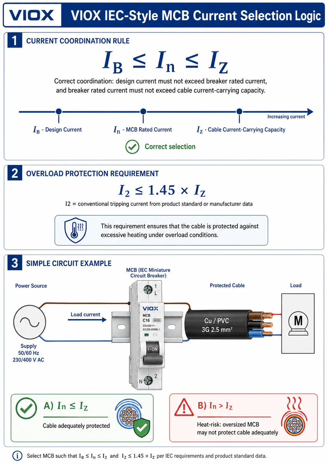
Where:
| Symbol | Meaning |
|---|---|
| IB | Design current of the circuit |
| In | Rated current of the protective device |
| IZ | Continuous current-carrying capacity of the conductor under installation conditions |
| I2 | Current ensuring effective operation of the protective device within the conventional time |
This logic prevents two common mistakes:
- choosing an MCB smaller than the expected design current, causing nuisance tripping
- choosing an MCB larger than the conductor can safely carry, creating overheating risk
The formula is only the overload part of selection. You still need to verify short-circuit breaking capacity, disconnection conditions, trip curve, voltage rating, and applicable local code.
A note on the 125% rule
Some older or North-America-focused guides use a “125% rule” for continuous loads. That rule belongs to specific NEC-style design contexts and should not be presented as a universal global MCB rule. For an IEC-oriented article, it is cleaner to lead with IB ≤ In ≤ IZ and I2 ≤ 1.45 × IZ, then mention North American continuous-load sizing only where the project is under NEC or equivalent local requirements.
Step 1: Determine Design Current IB
Start by calculating the maximum normal current expected in the circuit.
For a simple single-phase resistive load:
For three-phase loads:
where P is power, U is voltage, PF is power factor, and η is efficiency.
In real panels, also account for:
- diversity factor
- continuous duty
- motor starting current
- transformer inrush
- LED driver inrush
- ambient temperature
- future load expansion
- manufacturer instructions for connected equipment
Do not choose the MCB first and make the wire “fit” later. Choose the circuit architecture first, then select the protective device.
Step 2: Match MCB Current Rating to Conductor Ampacity
The MCB rated current In must not exceed the conductor’s usable ampacity IZ after derating.
Derating may be required because of:
- high ambient temperature
- multiple cables grouped together
- installation in conduit or trunking
- enclosure heat buildup
- insulation type
- cable tray spacing
- terminal temperature limits
In panel building, this detail is often missed when an MCB is selected from a catalog table without checking the actual wiring environment. A 32A MCB does not protect a conductor safely if the conductor’s derated ampacity is below 32A.
For distribution-board context, VIOX’s distribution box selection guide explains how circuit breakers, busbars, neutral bars, earth bars, and SPDs fit together inside the box.
Step 3: Choose the Trip Curve Based on Inrush Current
Trip curve selection determines when the magnetic instantaneous trip operates. The curve does not change the MCB’s continuous current rating.
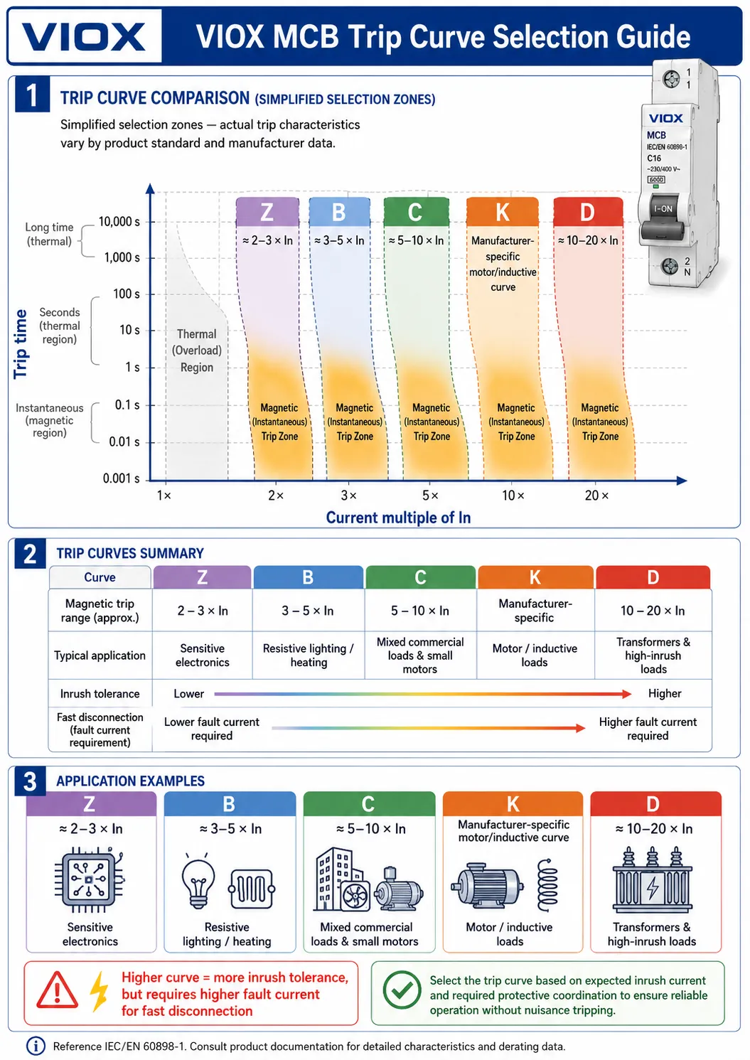
| Curve | Instantaneous trip range | Best fit | Main risk if misused |
|---|---|---|---|
| B | 3-5 × In | Low-inrush resistive loads, simple lighting, domestic-style circuits | Nuisance trips on motors, transformers, and large LED driver groups |
| C | 5-10 × In | Mixed loads, commercial circuits, small motors, moderate inrush | May need higher fault current than B curve for fast disconnection |
| D | 10-20 × In | High-inrush loads, transformers, large motors | Can fail fast-disconnection requirements if fault current is too low |
| K | Manufacturer-specific, often motor/inductive focused | Motors and inductive loads where available | Must be checked against manufacturer curve and standard |
| Z | Low instantaneous threshold | Sensitive electronics and control circuits | Can nuisance-trip if load has unexpected inrush |
For a deeper explanation of B, C, D, K, and Z characteristics, use VIOX’s dedicated Understanding Trip Curves article. For a focused inrush-current article, see MCB B, C, and D Curves Explained.
Curve selection is not a nuisance-trip workaround
Moving from B to C or from C to D increases inrush tolerance, but it also raises the magnetic trip threshold. That means the circuit must be able to deliver enough fault current for fast operation under short-circuit conditions.
Example:
- B16 magnetic trip upper band: about 80A
- C16 magnetic trip upper band: about 160A
- D16 magnetic trip upper band: about 320A
If the far end of the circuit cannot deliver that fault current, the breaker may still trip thermally, but not fast enough for the required short-circuit protection objective.
Step 4: Select Breaking Capacity: 6kA, 10kA, or Higher?
Breaking capacity, also called interrupting capacity, is the maximum prospective short-circuit current the MCB can safely interrupt under specified conditions.
The key rule:
The MCB breaking capacity must be equal to or greater than the prospective short-circuit current at the installation point.
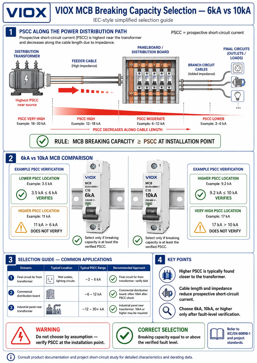
| Situation | Typical decision logic |
|---|---|
| Final circuits far from supply transformer | 6kA may be sufficient if PSCC is verified below rating |
| Commercial distribution boards | 10kA is often selected for higher margin, but still verify PSCC |
| Industrial control panels near low-impedance supply | 10kA or higher may be required |
| OEM equipment for multiple markets | Use product standard and panel SCCR strategy; do not assume 6kA is enough |
| Unknown PSCC | Do not guess; calculate, measure, or obtain utility/engineering data |
For the detailed comparison, see VIOX’s MCB Breaking Capacity 6kA vs 10kA Selection Guide. This page gives the selection logic; the dedicated breaking-capacity guide goes deeper into fault-current evaluation.
Step 5: Choose the Right Standard: IEC 60898-1, IEC 60947-2, or UL 489
The standard changes the application context and rating language.
| Standard | Main application context | Key selection point |
|---|---|---|
| IEC 60898-1 | Circuit breakers for household and similar installations | Uses ratings such as Icn; common in residential and similar final circuits |
| IEC 60947-2 | Industrial low-voltage circuit breakers | Uses Icu, Ics, utilization in industrial assemblies, and broader performance data |
| UL 489 | Branch-circuit protection in North America | Required for branch circuit protection in UL/NEC-style applications |
| UL 1077 | Supplementary protectors inside equipment | Not a substitute for a UL 489 branch circuit breaker unless upstream protection is already provided |
This matters for OEMs and panel builders. A breaker that is acceptable in an IEC control panel may not automatically satisfy a North American branch-circuit requirement. Conversely, a UL 1077 supplementary protector is not the same as a UL 489 branch circuit breaker.
For practical marking interpretation, use VIOX’s guide on How to Read the Nameplate of a Miniature Circuit Breaker. Nameplate details such as rated current, voltage, curve, breaking capacity, and standard reference should always be checked before approving a model.
Step 6: Select the Number of Poles
Pole selection depends on what conductors must be interrupted and what the local wiring rules require.
| Pole type | Typical use | Notes |
|---|---|---|
| 1P | One phase conductor | Common for simple final circuits where neutral is not switched |
| 1P+N | Phase protected, neutral switched | Common in compact distribution boards; check exact product function |
| 2P | Two conductors switched/protected depending on product design | Used in single-phase circuits requiring double-pole disconnection |
| 3P | Three-phase circuits without switched neutral | Common for three-phase loads |
| 4P / 3P+N | Three phases plus neutral | Used where neutral switching or isolation is required |
For three-phase motors and equipment, ensure common trip behavior is suitable. Do not assemble unrelated single-pole breakers as if they are a factory-designed multipole protective device unless the manufacturer and code allow that arrangement.
Step 7: Check Voltage Rating and AC/DC Suitability
The MCB voltage rating must match or exceed the circuit voltage. Pay special attention to DC systems.
DC interruption is harder than AC interruption because DC has no natural current zero crossing. A breaker that is rated for AC use is not automatically suitable for DC use. DC MCBs may require correct polarity, a specific number of poles in series, or a defined wiring direction.
For DC breaker selection, use VIOX’s DC circuit breaker guide for solar, battery, and EV systems rather than treating an AC MCB as universal.
MCBs in Distribution Boxes, Control Panels, and OEM Equipment
This is where VIOX’s MCB selection should feel more industrial than a basic household guide.
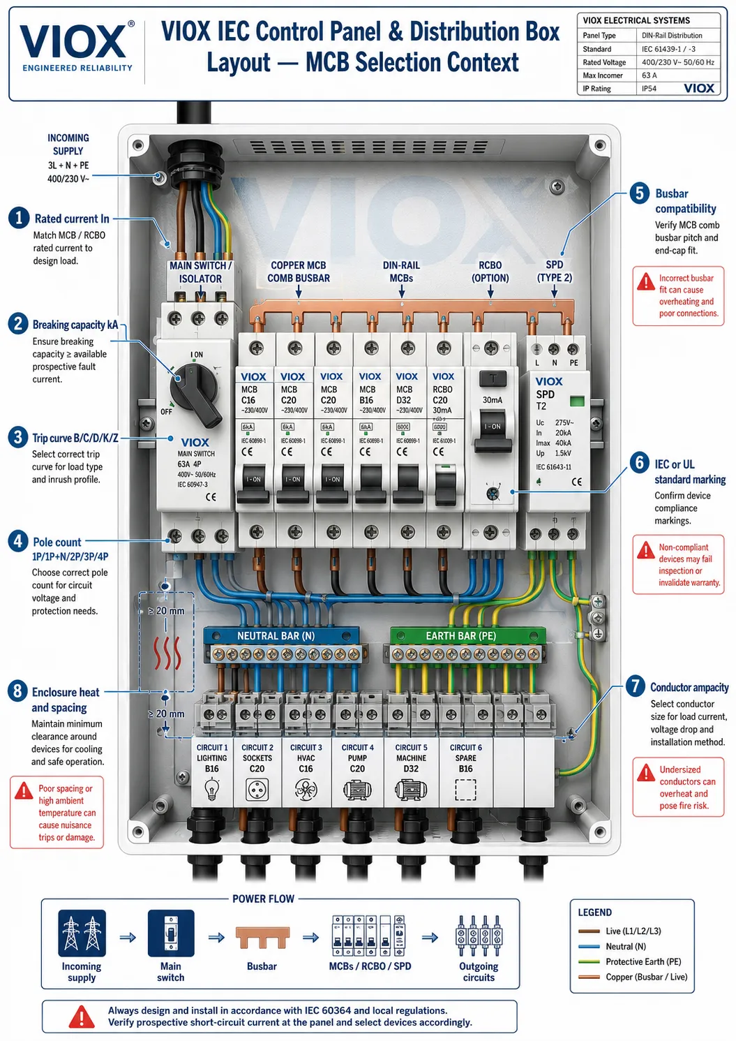
Distribution boxes
In distribution boxes, MCBs protect outgoing circuits and work alongside:
- busbars
- neutral and earth bars
- RCCBs or RCBOs
- SPDs
- incoming isolators or main breakers
- enclosure and cable-entry systems
The MCB must match the busbar system, pole configuration, short-circuit rating, terminal capacity, and available enclosure space. For busbar matching, see MCB Busbar Compatibility Guide and How to Select the Right Busbar for MCB.
Industrial control panels
In control panels, MCBs often protect control transformers, power supplies, solenoid circuits, PLC power, auxiliary circuits, lighting, and small branch circuits. Here the main questions are:
- Is the MCB branch protection or supplementary protection?
- Does the panel require IEC or UL construction?
- What is the panel short-circuit current rating (SCCR) or equivalent fault strategy?
- Does the connected device manual require a specific protective device?
- Is the curve suitable for power supply or transformer inrush?
For broader panel context, see VIOX’s Industrial Control Panel Components Guide.
OEM equipment
OEM buyers usually need repeatable model selection, stable supply, marking consistency, and accessory compatibility. In this context, MCB selection should include:
- standard and certification target
- curve availability across current ratings
- 1P, 2P, 3P, and 4P family coverage
- busbar and terminal compatibility
- auxiliary contact and shunt trip options where needed
- packaging, labeling, and documentation for export markets
- lifecycle and replacement consistency
This is where VIOX can support model mapping rather than simply selling a breaker by amp rating.
Can an MCB Protect Motors?
An MCB can provide short-circuit and overload protection to a circuit, but it is not always sufficient as complete motor protection.
Motor circuits may require:
- overload relay
- motor protection circuit breaker (MPCB)
- contactor
- phase-loss protection
- undervoltage protection
- soft starter or variable frequency drive protection strategy
- manufacturer-specified fuse or breaker coordination
For motor-specific protection, use VIOX’s Motor Protection Circuit Breaker Guide and MCB vs Voltage Monitoring Relay for Motor Protection.
When Should You Use RCBO Instead of MCB?
An MCB protects against overload and short circuit. It does not detect earth leakage or residual current. If the circuit also needs residual-current protection, use an RCCB plus MCB arrangement or an RCBO depending on the panel strategy.
Use an RCBO when:
- individual circuit residual-current protection is needed
- nuisance trips should be limited to one circuit
- space allows combined overcurrent and residual-current protection
- the installation standard or project specification requires it
The important point is simple: MCB and RCBO are not interchangeable protection functions. Use an MCB when overload and short-circuit protection are enough; use an RCBO when the same final circuit also needs residual-current protection.
Practical MCB Selection Workflow
Use this engineering sequence before approving an MCB:
- Define system: AC/DC, voltage, frequency, phase, earthing system, market.
- Define load: normal current, duty cycle, inrush, motor/transformer/electronic behavior.
- Select conductor: cross-section, insulation, installation method, derating.
- Choose In: satisfy IB ≤ In ≤ IZ.
- Verify overload operation: check I2 ≤ 1.45 × IZ where applicable.
- Calculate or obtain PSCC at the installation point.
- Choose breaking capacity: 6kA, 10kA, or higher as required by PSCC.
- Choose trip curve: B/C/D/K/Z based on inrush and fault-current availability.
- Choose poles: 1P, 1P+N, 2P, 3P, or 4P.
- Confirm standard: IEC 60898-1, IEC 60947-2, UL 489, or UL 1077 depending on application.
- Verify accessories: busbar, auxiliary contact, shunt trip, enclosure, terminal compatibility.
- Check documentation: markings, datasheet, approvals, and project specification.
Common MCB Selection Mistakes
Mistake 1: Oversizing the MCB to stop tripping
Frequent tripping is a symptom. It may be caused by overload, short circuit, inrush, wrong curve, poor connection, heat, or equipment fault. Increasing the current rating without checking conductor ampacity can remove protection from the cable.
Mistake 2: Choosing C curve or D curve without checking fault current
C and D curves tolerate more inrush, but they require higher fault current for instantaneous operation. This is especially important at the far end of long cable runs.
Mistake 3: Assuming 6kA is always enough
6kA may be suitable in some final circuits, but not where PSCC is higher. Verify the actual fault level instead of using the cheapest breaking capacity.
Mistake 4: Confusing IEC 60898-1 and IEC 60947-2 applications
Both standards deal with circuit breakers, but they are not used in the same way. Industrial panels and OEM equipment often need IEC 60947-2 data or UL 489 branch protection depending on market.
Mistake 5: Using UL 1077 supplementary protectors as branch protection
In North American contexts, UL 1077 devices are supplementary protectors, not substitutes for UL 489 branch circuit breakers unless the required upstream protection architecture is already present.
Mistake 6: Ignoring heat inside the enclosure
MCBs are tested under reference conditions. Dense enclosures, high ambient temperature, adjacent heat sources, and poor ventilation can affect performance and connection reliability.
Mistake 7: Ignoring busbar compatibility
Busbar mismatch can cause poor contact, overheating, or unsafe installation. The MCB and busbar system must be mechanically and electrically compatible.
MCB Buyer Checklist for VIOX Projects
When requesting MCB selection support, provide:
- target market: IEC, UL/North America, or mixed export
- AC or DC circuit
- system voltage and frequency
- rated load current and load type
- inrush profile if motor, transformer, LED, or power supply
- conductor size and installation method
- expected PSCC or panel SCCR requirement
- required breaking capacity
- curve preference or load curve requirement
- pole configuration
- busbar type and panel layout
- auxiliary contact, shunt trip, or accessory needs
- required markings, packaging, and documentation
This lets the supplier map a breaker family correctly instead of guessing from “16A C curve” alone.
FAQ
Should I choose a 6kA or 10kA MCB?
Choose based on the prospective short-circuit current at the installation point. If PSCC is below the device’s rated breaking capacity, the rating may be acceptable. Many commercial and industrial panels choose 10kA or higher for margin, but the correct answer comes from fault-level verification, not habit.
Should I use B curve or C curve MCB?
Use B curve for low-inrush loads where faster magnetic operation at lower fault current is useful. Use C curve for mixed loads or moderate inrush such as small motors, LED driver groups, and commercial circuits, provided the circuit has enough fault current for correct disconnection.
When should I use D curve MCB?
Use D curve only for high-inrush loads such as transformers, large motors, or similar equipment, and only after checking fault-current availability. D curve is not a universal solution for nuisance tripping.
What is the IEC formula for choosing MCB current rating?
The common IEC overload protection logic is IB ≤ In ≤ IZ and I2 ≤ 1.45 × IZ. This coordinates design current, breaker rating, and conductor current-carrying capacity.
What is the difference between IEC 60898-1 and IEC 60947-2 MCBs?
IEC 60898-1 is mainly for household and similar circuit-breaker applications. IEC 60947-2 is for industrial low-voltage circuit breakers and uses industrial rating concepts such as Icu and Ics. Choose according to the installation and panel context.
Is UL 489 the same as IEC 60898-1?
No. UL 489 is the North American branch-circuit breaker standard. IEC 60898-1 is an IEC standard for household and similar circuit breakers. Export panels should verify the required market standard rather than assuming one replaces the other.
Can an MCB protect a motor?
An MCB may provide short-circuit protection for the circuit, but complete motor protection often requires overload protection, contactor coordination, phase-loss consideration, or an MPCB. Check the motor and equipment manufacturer’s requirements.
When should I use RCBO instead of MCB?
Use RCBO when the circuit needs both overcurrent protection and residual-current protection in one device. An MCB alone does not detect earth leakage.
Can I replace an MCB with a larger current rating?
Only if the conductor ampacity, installation method, fault conditions, and code requirements allow it. Increasing the MCB rating to stop tripping without checking the circuit can create fire risk.
What information should I provide when asking VIOX to select an MCB?
Provide load current, voltage, AC/DC type, trip curve requirement, breaking capacity, pole count, standard or market, conductor size, panel type, busbar arrangement, and any accessory requirements.
Conclusion
Choosing the right MCB is not a one-line catalog decision. The correct breaker must match the load current, conductor ampacity, breaking capacity, trip curve, voltage, pole configuration, product standard, panel architecture, and market requirement.
For IEC panels, the core current relationship is:
and:
For real products, the next step is verifying curve, kA rating, poles, standard, busbar compatibility, and enclosure conditions.
Need help selecting MCBs for IEC panels, distribution boxes, or OEM projects? Contact VIOX for model selection support and product matching across MCB ratings, trip curves, breaking capacities, poles, and panel accessories.
Sources Reviewed
- IEC 60947-2:2016 – Low-voltage switchgear and controlgear circuit-breakers
- IEC 60898-1:2015+AMD1:2019 CSV – Circuit-breakers for overcurrent protection for household and similar installations
- ABB – UL489 Miniature Circuit Breakers
- UL – Molded Case Circuit Breaker Marking Guide
- VIOX – MCB Breaking Capacity 6kA vs 10kA Selection Guide
- VIOX – Understanding Trip Curves
