On this page
A circuit breaker symbol identifies a protective switching function on an electrical drawing. There is no single symbol that is correct for every drawing: the representation depends on the symbol system, the type of diagram, and the project legend.
The graphic alone may not identify whether a breaker is an MCB, MCCB, ACB, VCB, or SF6 circuit breaker. Engineers often use a base circuit breaker symbol together with a device tag, pole count, voltage class, protection function, or equipment label. Always read the symbol and its annotations as one unit.
Circuit Breaker Symbols Reference Chart
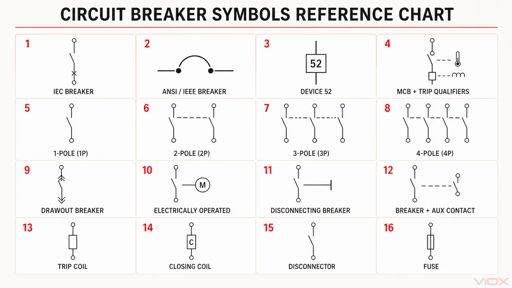
The chart below groups 16 commonly encountered breaker representations and related drawing elements. It is an interpretation aid, not a substitute for the symbol library and legend specified for a project. Exact geometry can vary with the drawing system, diagram type, CAD library, utility convention, and manufacturer documentation.
How the chart is organized
- Standards-oriented representations and identifiers (1–4): an IEC-oriented breaker function, the horizontal ANSI/IEEE breaker representation, device number 52, and an MCB shown with thermal and magnetic trip qualifiers.
- Pole configurations (5–8): 1P, 2P, 3P, and 4P arrangements. Dashed lines indicate mechanical linkage between poles; they do not represent electrical conductors.
- Construction and operating functions (9–12): drawout, electrically operated, disconnecting, and breaker-plus-auxiliary-contact representations. These features may be shown beside the main symbol or on another drawing sheet through a cross-reference.
- Control and adjacent devices (13–16): trip coil, closing coil, disconnector, and fuse. The last two are included because they are commonly confused with circuit breakers, not because they are breaker types.
Quick identification table
| Drawing item | What the drawing normally communicates | What to verify |
|---|---|---|
| General circuit breaker | A switching device capable of interrupting current automatically under defined conditions | Symbol standard, device tag, rating and protection notes |
| Single-pole breaker | One protected pole or one pole represented on the diagram | Whether the drawing is single-line or multi-line |
| Multi-pole breaker | Mechanically linked poles, often shown as repeated contacts or identified by a pole label | 2P, 3P, 4P, 1P+N or 3P+N configuration |
| MCB | Usually a breaker symbol with an MCB or QF-style device reference | Rated current, trip curve, breaking capacity and product standard |
| MCCB | Usually a breaker symbol identified by MCCB, frame information or trip-unit data | Frame size, trip unit and interrupting rating |
| ACB | Often identified by an ACB label, drawout notation or switchgear reference | Fixed or drawout construction and control circuit references |
| VCB | Commonly identified by VCB text or a medium-voltage equipment tag | Voltage class, truck position and project legend |
| SF6 circuit breaker | Commonly identified by an SF6 or high-voltage equipment label | Equipment technology and substation drawing convention |
| GFCI or AFCI breaker | A breaker symbol with a project-specific text label or qualifier | Do not assume one universal graphic; check the legend |
| RCCB or RCBO | Breaker or switching-device representation combined with residual-current identification | Device function, overcurrent protection and regional terminology |
| Motor-operated breaker | Breaker symbol linked to an operating mechanism or motor-control notation | Control power, close coil, trip coil and interlocks |
| Auxiliary or alarm contact | A separate contact associated with the breaker through a tag or cross-reference | Normal state, terminal numbering and manufacturer diagram |
The most reliable identification comes from four elements used together: graphic symbol, device tag, adjacent ratings, and drawing legend.
IEC vs ANSI Circuit Breaker Symbols
IEC graphical symbols
IEC 60617 is the official IEC database for graphical symbols used in electrotechnical diagrams. It is a maintained database rather than a set of current standalone paper parts. The database includes symbol titles, graphical representations, reference numbers, application notes, and relationships between symbols.
An IEC-based drawing may construct a breaker representation from a switching contact and one or more qualifying symbols. The exact form can change with the function being communicated and the type of diagram. For that reason, a simplified symbol copied from one drawing should not automatically be treated as the only IEC circuit breaker symbol.
ANSI and North American drawings
North American drawings may use symbols and device designations inherited from IEEE/ANSI practice, company drafting standards, utility conventions, or CAD libraries. IEEE/ANSI 315-1975 is now classified by IEEE as inactive-reserved, although its symbols still appear in legacy documentation and established drawing systems.
Power-system drawings may also use device numbers. For example, 52 is commonly used to identify an AC circuit breaker in protection and control documentation. A device number is an identifier, not a replacement for the drawing legend or the breaker specifications.
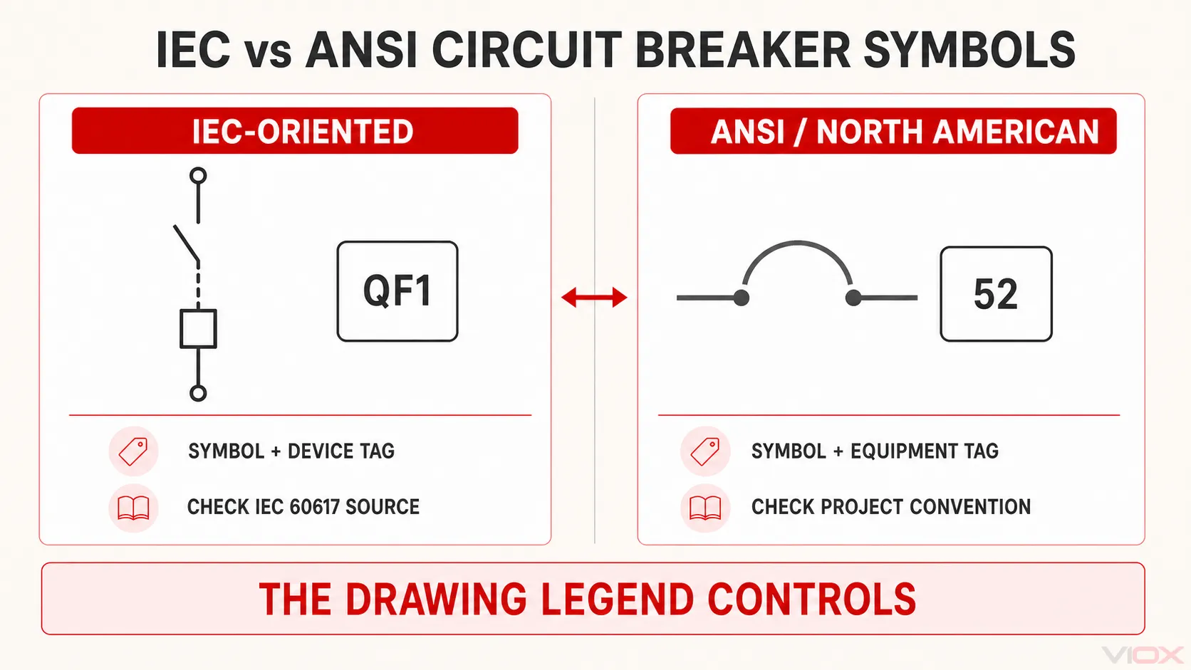
| Comparison point | IEC-oriented drawing | ANSI/North American drawing |
|---|---|---|
| Primary reference | IEC 60617 database | Project or utility convention; legacy IEEE/ANSI 315 symbols may appear |
| Device identification | Symbol plus class/reference designation and project tag | Symbol plus equipment tag or device number |
| Common source of variation | Function qualifiers and diagram type | Utility, manufacturer and legacy drafting conventions |
| Correct reading method | Check the IEC symbol reference used by the project and the legend | Check the drawing legend, device list and project drafting standard |
How to Read a Circuit Breaker Symbol
1. Identify the drawing type
A single-line diagram represents a multi-conductor power system in a simplified form. A multi-line schematic may show individual poles, operating coils, auxiliary contacts, and interlocks separately. Architectural plans can use a different notation again.
Do not expect the same amount of information from every drawing type.
2. Find the protective switching function
First distinguish the circuit breaker from a plain switch, disconnector, or fuse. A circuit breaker combines switching with automatic interruption under specified conditions. A disconnector primarily provides isolation, while a fuse interrupts by melting its element and must be replaced after operation.
A symbol can show a function without revealing the full construction of the product. Ratings and protection characteristics normally appear as adjacent text, a device tag, a schedule entry, or a separate specification.
3. Read the device tag and annotations
Look for labels such as CB, MCB, MCCB, ACB, VCB, QF, or a project-specific equipment number. Then check the associated information, which may include:
- rated current;
- system voltage;
- number of poles;
- interrupting or breaking capacity;
- trip-unit type or protection functions;
- fixed, plug-in, or drawout construction;
- normally open, normally closed, or normal service position.
The abbreviation is useful only within the drawing’s documented convention. For example, a QF-style tag is common in some IEC-oriented projects but should not be assumed to be universal.
4. Determine the number of poles
On a detailed schematic, linked contacts may show that the poles operate together. On a single-line diagram, one line can represent a complete three-phase circuit, so the number of drawn lines is not always the physical pole count.
Confirm the arrangement from labels such as 1P, 2P, 3P, 4P, 1P+N, or 3P+N. A switched neutral is not automatically an overcurrent-protected pole; the product documentation and schematic must make the function clear.
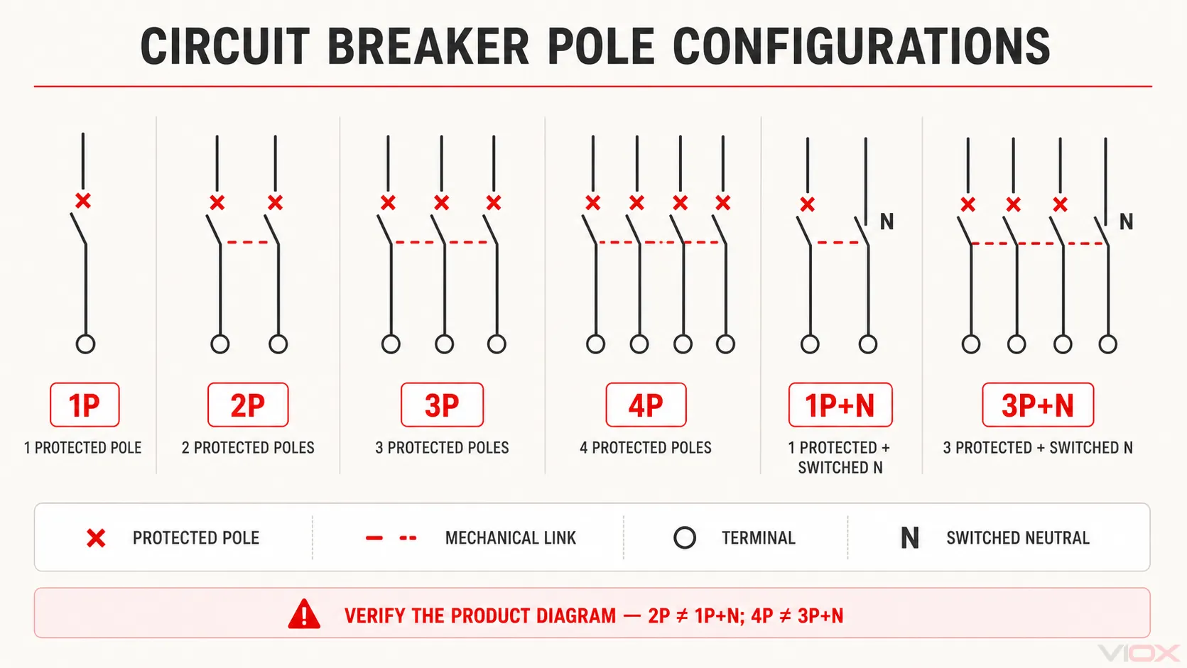
Use these reading rules:
- An × qualifier identifies a protected pole in this illustration.
- A dashed line indicates mechanical linkage between contacts, not an electrical connection.
- In a typical 1P+N arrangement, one phase pole is protected and the neutral pole is switched with it. In a typical 3P+N arrangement, the three phase poles are protected and the neutral is switched with them.
- 2P is not automatically equivalent to 1P+N, and 4P is not automatically equivalent to 3P+N. Verify which poles contain overcurrent releases from the breaker markings and manufacturer diagram.
5. Follow the cross-references
Trip coils, closing coils, undervoltage releases, shunt releases, alarm contacts, and position contacts may be drawn away from the main breaker symbol. Matching device tags and grid references connect these elements to the same physical breaker.
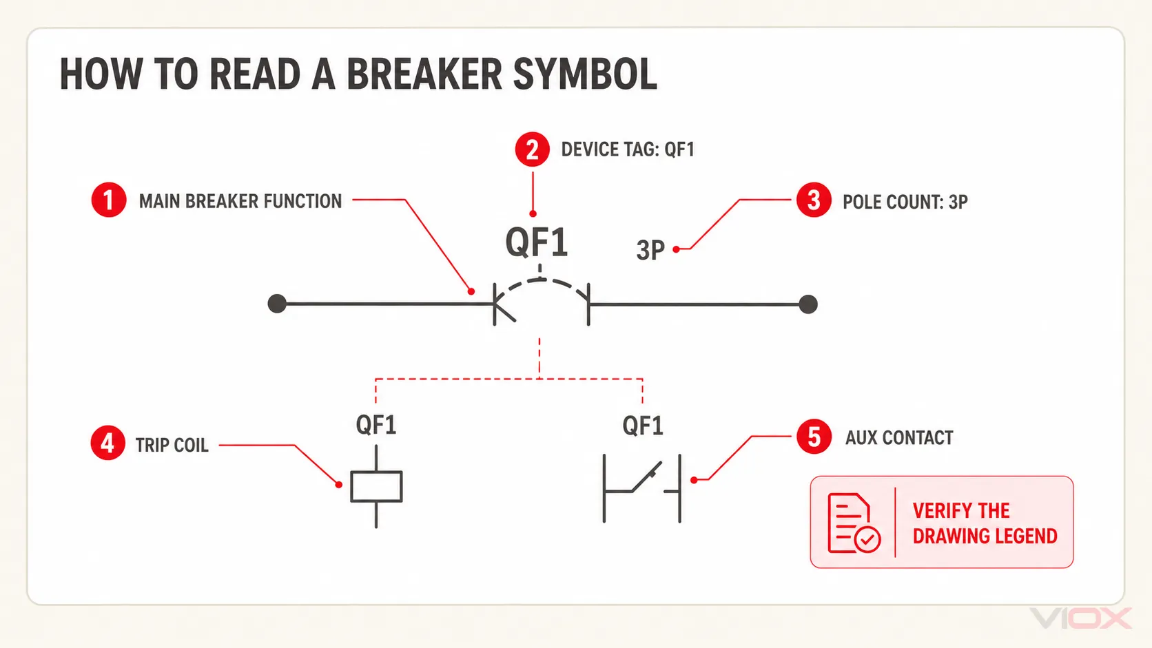
Symbols for MCB, MCCB, ACB, VCB and SF6 Breakers
The product name does not always produce a unique universal graphical symbol.
MCB and MCCB symbols
A miniature circuit breaker (MCB) and a molded case circuit breaker (MCCB) may use the same base breaker function on a single-line diagram. The distinction is often carried by the device tag, frame or current data, trip-unit information, and equipment schedule.
Do not infer the trip curve, breaking capacity, or applicable product standard from the graphic alone.
ACB, VCB and SF6 circuit breaker symbols
Air, vacuum, and SF6 describe the breaker technology or interrupting medium. Some drawing libraries provide specialized graphics, but many projects use a general circuit breaker symbol followed by an ACB, VCB, or SF6 label.
For a vacuum circuit breaker, the surrounding context is often more informative than the basic symbol: medium-voltage switchgear references, truck positions, earthing switches, protection relays, and control-circuit cross-references help confirm the device.
GFCI, AFCI, RCCB and RCBO notation
GFCI and AFCI protection requirements do not create one universally accepted breaker graphic for every electrical plan. Designers commonly add a text label, abbreviation, qualifier, or panel-schedule note. The project legend remains decisive.
The same rule applies to residual-current devices in IEC-oriented markets. An RCCB provides residual-current protection without integral overcurrent protection, while an RCBO combines residual-current and overcurrent protection. A drawing should make that functional difference clear instead of relying on a vague “RCD” label alone.
Circuit Breaker, Fuse, Switch and Disconnector Symbols
| Device | Main function communicated | Common interpretation risk |
|---|---|---|
| Circuit breaker | Switching plus automatic fault interruption | Mistaking it for a manually operated switch |
| Fuse | Overcurrent interruption by a replaceable element | Assuming it can be reset like a breaker |
| Switch | Making and breaking current under its specified duty | Assuming it provides automatic overcurrent protection |
| Disconnector or isolator | Isolation and a defined disconnection function | Assuming it can interrupt fault current |
| Switch-disconnector | Switching and isolation within its declared ratings | Treating it as a circuit breaker without overcurrent protection |
The equipment specification—not the visual similarity of two symbols—determines the device’s ratings and permitted duties.
Auxiliary Contact and Trip Contact Symbols
Auxiliary contacts report breaker status or participate in control logic. Alarm or trip-indication contacts may change state only after a protective trip. Position contacts can indicate open, closed, connected, test, or disconnected conditions on drawout equipment.
Terminal numbering must be verified against the manufacturer diagram. As one common example, Schneider Electric documentation identifies 95–96 as a normally closed fault-signalling contact and 97–98 as a normally open fault-signalling contact for specified devices. This numbering should not be generalized to every breaker accessory or manufacturer.
When reading auxiliary contacts:
- Match the contact tag to the parent breaker.
- Determine whether the drawing shows the normal, de-energized, or service state.
- Identify whether the contact reports breaker position, mechanism state, or protective trip.
- Verify terminal numbers in the product wiring diagram.
Common Circuit Breaker Symbol Mistakes
Assuming one symbol is universal
IEC, North American, utility, manufacturer, and project-specific conventions can differ. Use the legend before assigning a meaning.
Identifying breaker technology from shape alone
A VCB, ACB, or SF6 breaker may use a general circuit breaker symbol with a text identifier. The symbol shape alone may not reveal the interrupting medium.
Reading ratings into the graphic
Current rating, voltage, breaking capacity, trip curve, and trip settings normally come from annotations, schedules, or device data—not from the basic breaker symbol.
Confusing code requirements with symbol standards
Installation codes define where particular protection may be required. They do not necessarily prescribe one universal CAD symbol for every project. Keep protection requirements and drawing conventions separate.
Ignoring the normal-state convention
Contacts are often shown in a defined normal condition, but that condition must be stated or understood from the drawing rules. Incorrectly assuming the operating state can reverse the interpretation of an interlock or alarm circuit.
Frequently Asked Questions
What is the standard symbol for a circuit breaker?
There is no single graphic that applies to every drawing worldwide. IEC-oriented projects reference the IEC 60617 database, while North American and legacy drawings may use different conventions. Always confirm the project legend and drawing standard.
What is the IEC circuit breaker symbol?
IEC 60617 contains graphical symbols and qualifying elements for electrotechnical diagrams. The exact breaker representation depends on the function and diagram context. Use the official IEC 60617 database or a licensed, project-approved symbol library for the exact geometry and reference number.
Is the MCB symbol different from the MCCB symbol?
Not necessarily. A single-line diagram may use the same basic breaker symbol and distinguish the products with MCB or MCCB tags, ratings, frame information, and trip-unit data.
What is the symbol for a vacuum circuit breaker?
Some symbol libraries provide a specialized representation, but many drawings use a general breaker symbol labeled VCB. Verify the equipment tag, voltage class, switchgear context, and legend rather than relying on shape alone.
How is a GFCI breaker shown on a drawing?
The notation varies. It may be identified by GFCI, GF, a project-defined qualifier, or a panel-schedule note. Do not assume that a wavy line, ground mark, or other graphic has the same meaning on every drawing.
What does 52 mean next to a circuit breaker?
In power-system protection and control documentation, device number 52 commonly identifies an AC circuit breaker. The complete tag may include additional letters or numbers that identify location, voltage level, or equipment sequence.
How do I distinguish a circuit breaker from a disconnector?
A circuit breaker has an automatic fault-interruption function. A disconnector provides isolation and is not automatically equivalent to a breaker. Check the symbol qualifiers, device tag, equipment specification, and project legend.
Final Reading Rule
Treat a circuit breaker symbol as the starting point, not the complete specification. A reliable interpretation combines the symbol with the drawing type, equipment tag, ratings, cross-references, and project legend. When these sources conflict, stop and verify the approved drawing standard or equipment documentation before using the diagram for design, operation, or maintenance.