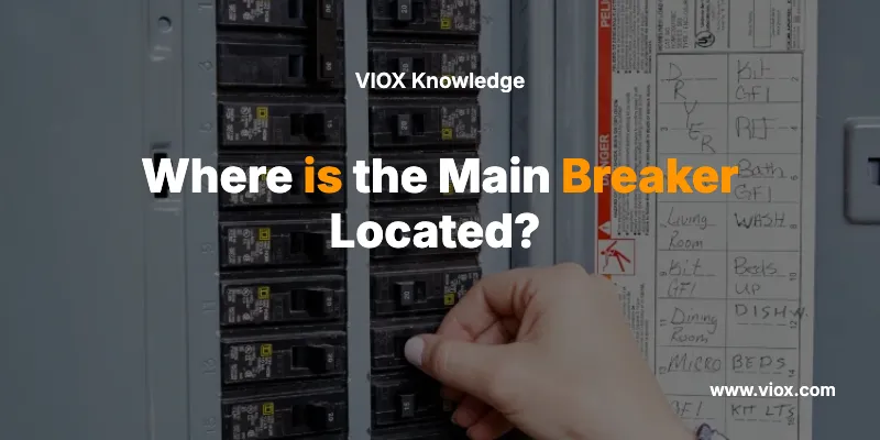
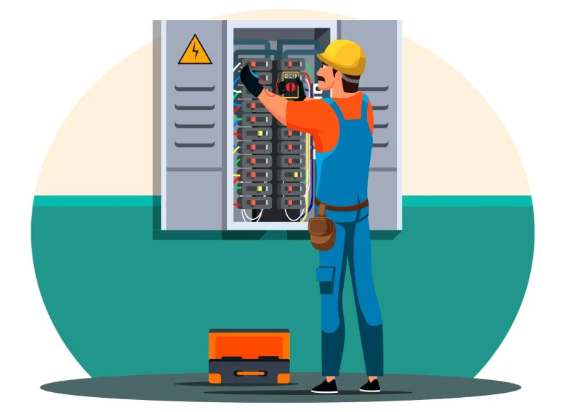
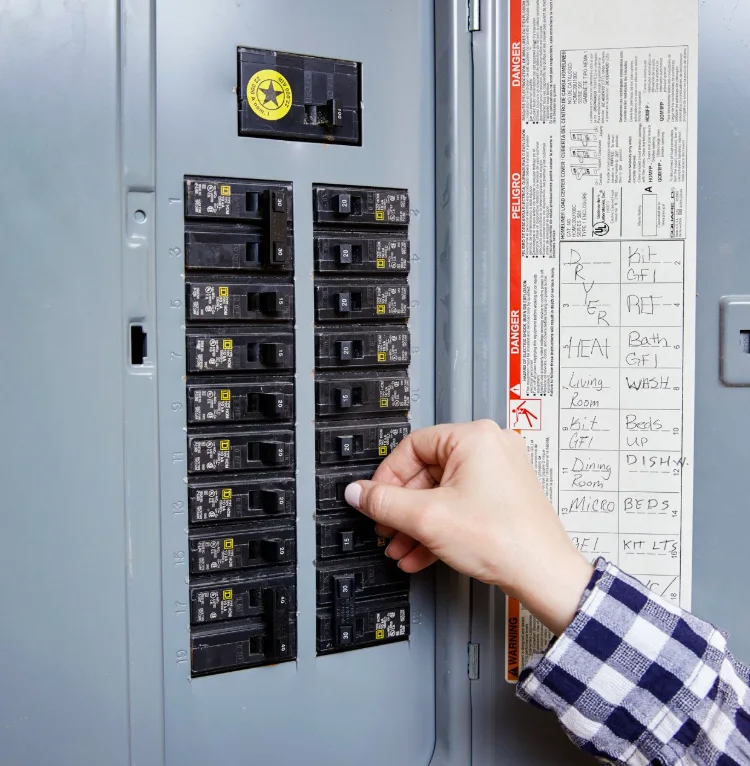
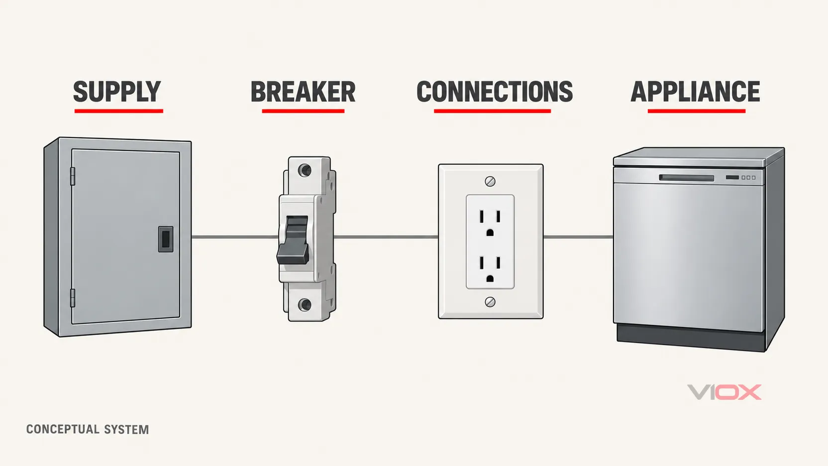
The main breaker is typically located at the top of your home’s electrical panel (breaker box), which is most commonly found on an exterior wall, in the basement, garage, utility room, or near the electric meter. Understanding your main breaker’s location is crucial for emergency power shutoffs and electrical safety.
⚠️ SAFETY WARNING: Always exercise extreme caution around electrical panels. If you’re unsure about any electrical work, consult a licensed electrician immediately.
What is a Main Breaker and Why Does Location Matter?
Main Breaker Definition
A main breaker is the primary circuit breaker that controls all electrical power entering your home from the utility company. It acts as the master shutoff switch for your entire electrical system, typically rated between 100-200 amps for residential properties.
Why Knowing the Location is Critical
Emergency shutoffs during electrical fires or flooding
Electrical work preparation by contractors
Power management during storms or outages
Safety compliance with local electrical codes
Home inspection requirements for real estate transactions
Main Breaker Location by Home Type: Quick Reference Table
Home Type
Most Common Location
Secondary Locations
Access Notes
Single-Family Home
Garage or exterior wall
Basement, utility room
Usually at eye level
Townhouse/Condo
Interior utility closet
Garage, basement
May be shared panel
Apartment
Kitchen/hallway closet
Bedroom closet
Often labeled unit number
Mobile Home
Exterior panel near meter
Under-home utility area
Weather-protected box
Older Homes (Pre-1960)
Basement near meter
Fuse box instead of breakers
May need electrical upgrade
Step-by-Step Guide to Locating Your Main Breaker
Step 1: Start with the Electric Meter
Go outside and locate your electric meter (usually mounted on exterior wall)
Look nearby for a gray or tan metal box (electrical panel)
Check within 10 feet of the meter – code requires close proximity
Step 2: Check Common Interior Locations
Basement: Near where power lines enter the home
Garage: Along walls, typically opposite the house entrance
Utility room: Often combined with water heater/HVAC equipment
Kitchen area: In older homes, sometimes in kitchen closets
Hallway closets: Especially in apartments and condos
Step 3: Identify the Main Breaker
Open the panel cover (if safe to do so)
Look for the largest breaker – usually at the top
Check the label – should read “MAIN” or show highest amperage (100A, 150A, 200A)
Verify it controls multiple circuits – not just one outlet or appliance
Expert Tip: The main breaker is typically twice the width of standard circuit breakers and has two switches that move together.
Main Breaker Types and Configurations
Standard Main Breaker Panel
Location: Top of electrical panel
Appearance: Double-wide breaker switch
Function: Controls all power to sub-breakers below
Rating: Usually matches panel capacity (100A-200A)
Main Lug Panel (No Main Breaker)
Location: Power controlled by exterior disconnect
Appearance: No main breaker in panel
Function: Direct connection from meter to panel
Safety Note: Must locate exterior disconnect for shutoff
Accessibility: Cannot be blocked by storage or furniture
Labeling: All breakers must be clearly labeled
Grounding: Proper grounding rod connection required
⚠️ Professional Recommendation: Never remove the main panel cover unless you’re a qualified electrician. Exposed bus bars carry lethal voltage even when main breaker is off.
Emergency Shutoff Procedures
When to Use Main Breaker Shutoff
Electrical fires – Shut off immediately before calling 911
Flooding – Turn off before water reaches electrical components
Gas leaks – Eliminate ignition sources
Major electrical work – Required by code for safety
Storm preparation – Prevent power surge damage
Safe Shutoff Steps
Ensure dry conditions – Never touch electrical panels with wet hands
Stand to the side – Not directly in front of panel
Use insulated tools if available
Flip main breaker to OFF – Should click firmly into position
Verify power is off – Check lights and outlets
Call professionals for electrical issues
Troubleshooting: What If You Can’t Find Your Main Breaker?
Common Scenarios and Solutions
Problem: No main breaker visible in panel
Solution: Look for exterior disconnect switch near meter
Action: Check with electrician about panel upgrade needs
Problem: Multiple panels in home
Solution: Identify which contains the service entrance conductors
Action: Main breaker is in the first panel after the meter
Problem: Apartment/condo confusion
Solution: Check lease documents or contact property management
Code compliance issues discovered during inspection
Flickering lights or frequent breaker trips
Burning smells or visible damage around panel
Certification Requirements
Licensed electrician required for all main breaker work
Electrical permits needed for panel modifications
Inspection required after major electrical changes
Insurance compliance may require professional installation
Quick Reference Checklist for Main Breaker Location
Before You Need It
[ ] Locate and test your main breaker function
[ ] Ensure clear access path to electrical panel
[ ] Label all circuit breakers clearly
[ ] Keep flashlight near electrical panel
[ ] Post emergency electrician contact information
Emergency Preparedness
[ ] Know exact main breaker location
[ ] Practice safe shutoff procedure
[ ] Keep panel area clear of storage
[ ] Have backup lighting available
[ ] Know when to call professionals
Frequently Asked Questions
What should you look for when locating a main breaker?
The main breaker is typically the largest switch in your electrical panel, located at the top, and controls power to all other breakers. It’s usually rated for 100-200 amps and may be labeled “MAIN” or show the service capacity.
How do I know if my main breaker is working properly?
A properly functioning main breaker should flip firmly between ON and OFF positions, control power to your entire home, and not show signs of burning, corrosion, or loose connections. If you notice any issues, contact a licensed electrician immediately.
Can I replace a main breaker myself?
No. Main breaker replacement requires a licensed electrician due to safety risks and code requirements. Working on service entrance equipment can be deadly and may violate local electrical codes and insurance policies.
What’s the difference between a main breaker and circuit breakers?
The main breaker controls all electrical power entering your home from the utility, while circuit breakers control power to individual circuits (lights, outlets, appliances). The main breaker protects the entire electrical system.
Where is the main breaker in older homes?
Older homes may have the main breaker in the basement near where power lines enter, or may use a fuse box with a main fuse or knife switch instead of a modern circuit breaker panel.
How often should main breakers be inspected?
Main breakers should be professionally inspected every 3-5 years, or immediately if you notice flickering lights, burning smells, or other electrical issues. Annual visual inspections by homeowners are recommended.
What amp rating should my main breaker be?
Most modern homes use 150A or 200A main breakers. Older homes may have 100A service. The rating depends on your home’s electrical needs and should match your service entrance capacity.
Is it safe to flip the main breaker during a storm?
Yes, turning off the main breaker during severe storms can protect your home’s electrical system from power surges. However, only do this if you can safely reach the panel and aren’t standing in water.
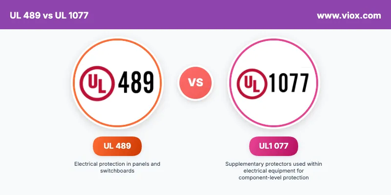
Direct Answer: UL 489 covers molded-case circuit breakers and switches used as main electrical protection in panels and switchboards, while UL 1077 covers supplementary protectors used within electrical equipment for component-level protection. The key difference is UL 489 devices provide primary electrical protection, while UL 1077 devices provide secondary protection.Understanding these two critical UL standards is essential for electrical contractors, engineers, and facility managers who need to select the right protective devices for their applications and ensure code compliance.
What Are UL 489 and UL 1077 Standards?
UL 489 Standard Definition
UL 489 is the Standard for Molded-Case Circuit Breakers, Molded-Case Switches, and Circuit-Breaker Enclosures. This standard governs the primary electrical protection devices you’ll find in electrical panels, switchboards, and motor control centers.
Key Applications:
Main electrical panels
Distribution switchboards
Motor control centers
Industrial control panels
Service entrance equipment
UL 1077 Standard Definition
UL 1077 is the Standard for Supplementary Protectors for Use in Electrical Equipment. These devices provide additional protection within electrical equipment and are not intended to be the sole means of protection.
⚠️ Safety Warning: Never substitute a UL 1077 device for a UL 489 device in primary protection applications. This violates electrical codes and creates serious safety hazards.
Applications and Use Cases
When to Use UL 489 Circuit Breakers
Primary Applications:
Main electrical service protection
Feeder circuit protection
Branch circuit protection in panels
Motor starter protection
Lighting panel protection
Specific Use Cases:
200A main breaker in residential panel
100A feeder to sub-panel
20A branch circuit for receptacles
30A motor protection
277V lighting circuits
When to Use UL 1077 Supplementary Protectors
Primary Applications:
Control circuit protection
Component protection within equipment
Secondary protection in machinery
Lighting control system protection
Electronic equipment protection
Specific Use Cases:
5A protection for PLC input circuits
2A protection for control transformers
10A protection for variable frequency drives
15A protection for lighting contactors
1A protection for electronic control modules
Selection Criteria and Best Practices
Choosing the Right Standard
Use UL 489 When:
You need primary electrical protection
Installing in main electrical panels
Protecting feeder or branch circuits
Meeting NEC Article 240 requirements
Requiring high interrupting capacity
Use UL 1077 When:
You need supplementary protection
Installing within electrical equipment
Protecting control circuits
Already have UL 489 primary protection
Requiring compact protection solutions
Expert Selection Tips
? Expert Tip: Always verify that UL 1077 devices are installed downstream of appropriate UL 489 protection. The UL 1077 device must be within the protective range of the upstream UL 489 device.
Technical Specifications to Consider:
Factor
UL 489 Considerations
UL 1077 Considerations
Current Rating
Match load and conductor ampacity
Match equipment requirements
Voltage Rating
Match system voltage
Match control circuit voltage
Interrupting Capacity
Match available fault current
Consider equipment withstand rating
Trip Characteristics
Match load type and starting current
Match component protection needs
Environmental Conditions
Consider panel environment
Consider equipment environment
Code Compliance and Safety Requirements
NEC Requirements
UL 489 Compliance:
Must comply with NEC Article 240
Required for overcurrent protection
Must be listed and labeled
Installation per manufacturer instructions
Proper coordination with conductors
UL 1077 Compliance:
Cannot be sole means of protection
Must be used with UL 489 protection
Equipment installation requirements
Marking and labeling requirements
Not recognized for branch circuit protection
Safety Considerations
⚠️ Critical Safety Warning: UL 1077 devices are not tested for the same fault current levels as UL 489 devices. Using them incorrectly can result in fire, equipment damage, or personal injury.
Professional Installation Requirements:
Both standards require installation by qualified electricians
Proper torque specifications must be followed
Arc flash hazard assessment required
Coordination study recommended for complex systems
Installation and Maintenance Guidelines
UL 489 Installation Best Practices
Step-by-Step Installation:
Verify Power Off: Confirm electrical power is de-energized and locked out
Check Compatibility: Ensure breaker matches panel manufacturer and specifications
Inspect Connections: Verify proper wire sizing and connection torque
Test Operation: Perform manual operation test before energizing
Document Installation: Record breaker specifications and settings
UL 1077 Installation Best Practices
Step-by-Step Installation:
Verify Primary Protection: Confirm UL 489 protection is properly installed upstream
Secure Mounting: Install per manufacturer mounting instructions
Verify Coordination: Confirm proper coordination with upstream protection
Test Functionality: Perform operational test within equipment system
Troubleshooting Common Issues
UL 489 Troubleshooting
Common Problems:
Nuisance tripping: Check for loose connections or overloading
Won’t reset: Verify fault is cleared and breaker isn’t damaged
Overheating: Check torque specifications and conductor sizing
Arc flash incidents: Ensure proper coordination and maintenance
UL 1077 Troubleshooting
Common Problems:
Frequent operation: Check for equipment overload or malfunction
Coordination issues: Verify proper relationship with upstream protection
Premature failure: Ensure proper application and environment
Incorrect application: Verify not being used for primary protection
Professional Recommendations
When to Consult an Expert
Mandatory Professional Consultation:
Arc flash hazard analysis
Coordination studies
Fault current calculations
Code compliance verification
Complex system design
? Expert Tip: Always have a qualified electrical engineer perform a coordination study when mixing UL 489 and UL 1077 devices in complex systems.
Quality and Reliability Factors
Choosing Quality Devices:
Select UL-listed devices only
Choose established manufacturers
Verify proper ratings and specifications
Consider long-term availability
Review manufacturer support
Quick Reference Guide
UL 489 Quick Facts
Purpose: Primary electrical protection
Location: Panels, switchboards, MCCs
Ratings: 15A to 6000A
Interrupting: Up to 200kA
Code: NEC Article 240 compliant
UL 1077 Quick Facts
Purpose: Supplementary protection
Location: Within electrical equipment
Ratings: 0.5A to 63A typically
Interrupting: Up to 10kA typically
Code: Must have UL 489 upstream
Frequently Asked Questions
What makes UL 489 different from UL 1077 in terms of safety?
UL 489 circuit breakers undergo extensive testing for primary protection applications, including high fault current interruption and endurance testing. UL 1077 supplementary protectors are tested for specific equipment applications with lower fault current requirements and cannot provide the same level of protection.
Can I use a UL 1077 device to replace a UL 489 circuit breaker?
No, this is never acceptable and violates electrical codes. UL 1077 devices are supplementary protectors that must be used in addition to, not instead of, UL 489 primary protection devices.
How do I determine the correct interrupting capacity for each standard?
For UL 489 devices, calculate the available fault current at the installation point and select a breaker with equal or greater interrupting capacity. For UL 1077 devices, consider the equipment’s withstand rating and ensure the upstream UL 489 device provides adequate protection.
Are there specific marking requirements for each standard?
Yes, UL 489 devices must be marked “Circuit Breaker” and include ratings, while UL 1077 devices must be marked “Supplementary Protector” and include appropriate warnings about their intended use.
What are the consequences of using the wrong standard?
Using UL 1077 devices for primary protection can result in inadequate fault protection, code violations, insurance issues, fire hazards, and potential personal injury. Always use the appropriate standard for each application.
How often should devices from each standard be maintained?
UL 489 circuit breakers in critical applications should be inspected annually and tested every 3-5 years. UL 1077 supplementary protectors should be inspected as part of equipment maintenance schedules, typically annually or per manufacturer recommendations.
Can both standards be used together in the same system?
Yes, this is common and often necessary. UL 489 devices provide primary protection while UL 1077 devices provide supplementary protection within equipment. Proper coordination between the devices is essential for optimal performance.
What training is required for installation and maintenance?
Both standards require installation by qualified electricians with appropriate training and certification. Complex systems may require additional training in coordination studies and arc flash safety.
Conclusion
Understanding the difference between UL 489 and UL 1077 is crucial for electrical safety and code compliance. UL 489 circuit breakers provide primary electrical protection in panels and switchboards, while UL 1077 supplementary protectors provide additional protection within electrical equipment. Never substitute one for the other, and always ensure proper coordination when using both standards in the same system.
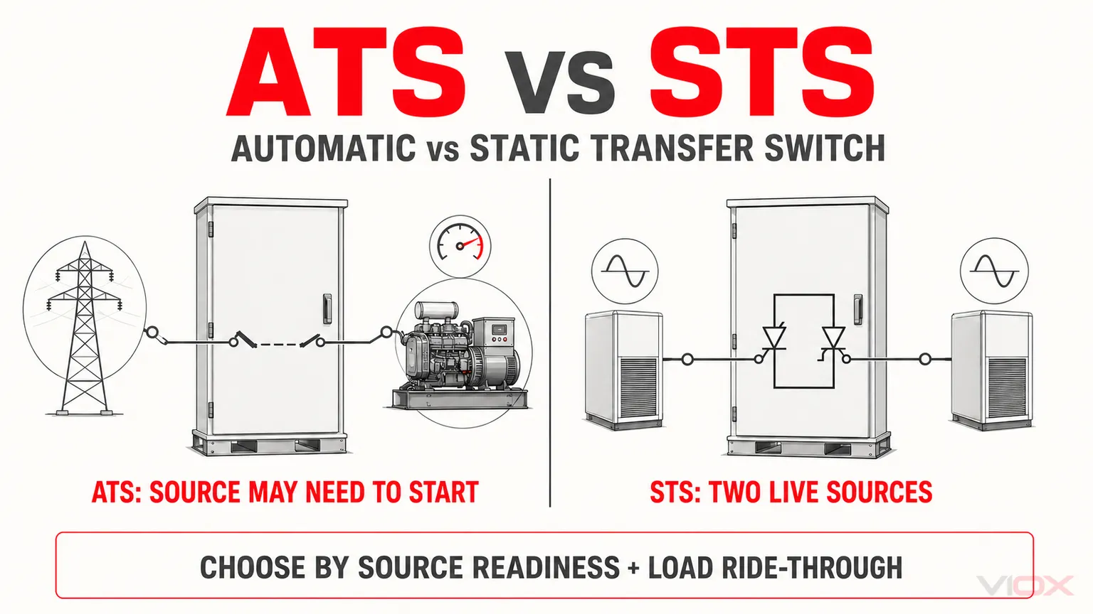
An automatic transfer switch (ATS) is normally the better fit when the alternate source may need to start, particularly in a utility-to-generator system, or when the load can tolerate the declared electromechanical transfer sequence. A static transfer switch (STS) is normally selected when two independent AC sources are already energized and acceptable and a sensitive load requires a much shorter transfer under the manufacturer’s declared source and load conditions.
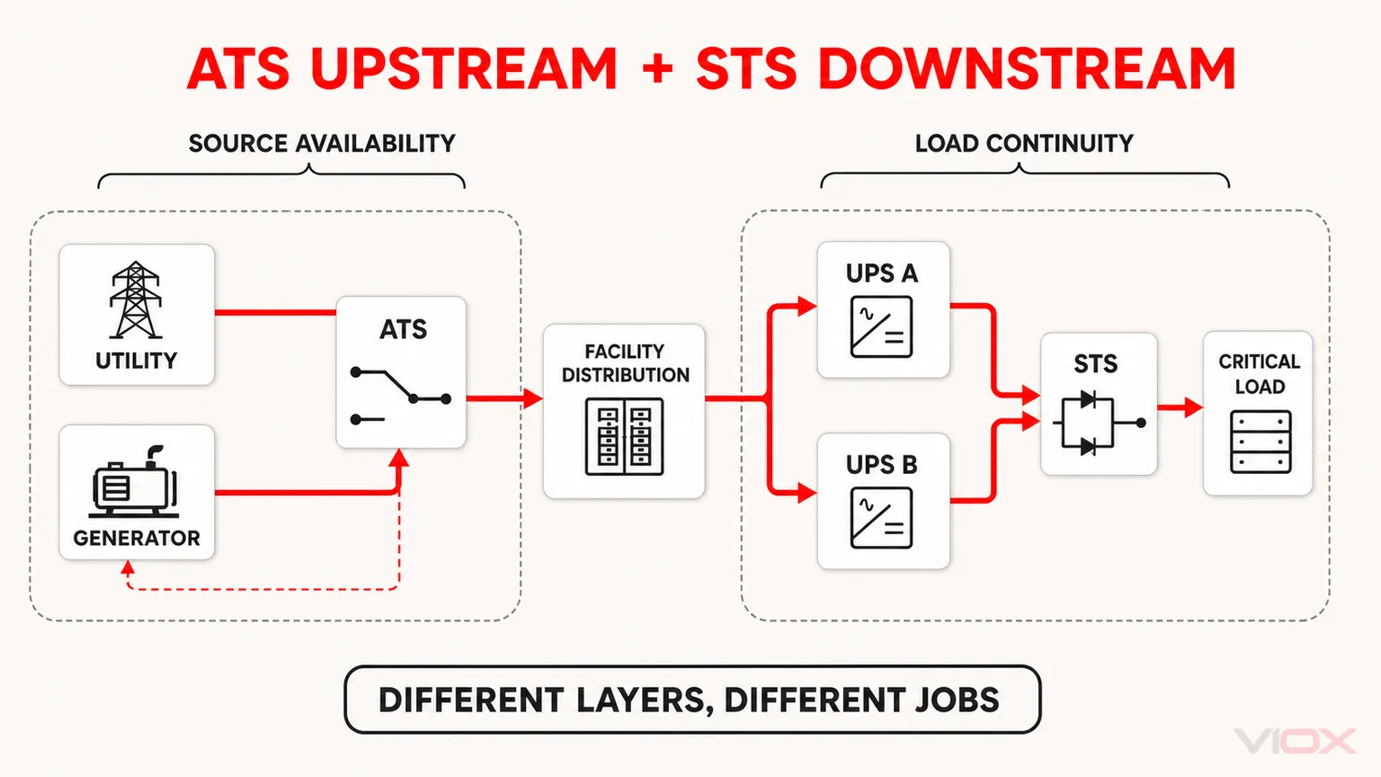
The devices are therefore not separated by speed alone. They solve different source-availability and continuity problems. In some critical-power systems, the correct answer is both: an ATS manages facility-level utility and generator sources, while a downstream STS transfers a critical load between two live UPS or distribution paths.
ATS vs STS at a Glance
Decision factor
Automatic transfer switch (ATS)
Static transfer switch (STS)
Switching path
Electromechanical contacts operated by a transfer mechanism
Solid-state power devices, commonly thyristor or SCR paths
Typical source arrangement
Utility-generator, generator-generator, or two available feeders
Two energized, monitored AC sources
Alternate source at failure
May be unavailable and require generator starting and stabilization
Normally already energized and within the STS acceptance window
Transfer behavior
Open transition is break-before-make; some systems support controlled closed transition
Fast solid-state source transfer controlled to prevent an unintended source-to-source current path
Load interruption
Depends on detection, source readiness, intentional delays, mechanism, and transition mode
Often sub-cycle or a few milliseconds, but depends on source relationship, load current, control logic, and product design
Main system role
Facility or distribution-level source transfer
Point-of-use or downstream protection of continuity-sensitive loads
Continuous conduction
Current flows through closed mechanical contacts
Current flows through semiconductor devices, creating continuous losses and heat that must be managed
Fault and protection design
Requires declared short-circuit ratings and system coordination
Requires declared ratings, semiconductor protection, bypass strategy, and system coordination
Principal IEC family
IEC 60947-6-1 for transfer switching equipment
IEC 62310-1 and IEC 62310-3 for static transfer systems
Typical selection trigger
The backup source must be started or electromechanical isolation is part of the architecture
Both sources are live and the load has limited ride-through capability
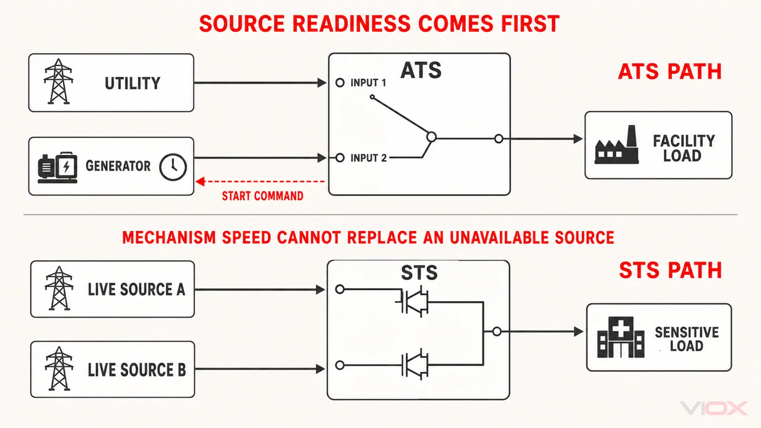
Selection rule: choose by source readiness first, acceptable load interruption second, and equipment ratings third. Do not select either device from an isolated transfer-time number.
ATS and STS source-readiness architecture showing utility and generator inputs for ATS and two live inputs for STS
Conceptual architecture only. The dashed line is a generator start command; solid lines are power paths. It is not a product wiring diagram.
Why Transfer-Time Numbers Can Be Misleading
A datasheet may publish a switching or commutation time, but that value is not necessarily the total time for power to be restored to the load. A useful engineering model separates four time components:
Time component
What it represents
Why it matters
Failure detection and confirmation
Time required to determine that the preferred source is outside its acceptable limits
Filters and programmed validation can prevent nuisance transfers but add delay
Alternate-source readiness
Time required for the alternate source to become usable
Generator starting, acceleration, voltage buildup, and frequency stabilization may dominate the outage
Programmed transfer delay
Intentional delay imposed by the controller or operating sequence
May support coordination, avoid transient transfers, or allow a source to stabilize
Switching or commutation interval
Time taken by the contacts or semiconductor path to move the load
This is often the number emphasized in product marketing
Conceptually:
Restoration time depends on detection + source readiness + programmed delay + transfer action.
These events can overlap, so this is a system model rather than a universal arithmetic formula. Its purpose is to show why a fast mechanism cannot compensate for a generator that has not started. The detailed ATS switching-time guide explains why published values must be tied to a specific transfer sequence.
An STS usually avoids the source-starting component because both inputs are expected to be energized. That architectural difference, not the absence of moving parts by itself, is the main reason an STS can restore an eligible load much faster.
How an ATS Transfers Power
An ATS monitors the preferred source and commands an electromechanical transfer mechanism when its control criteria are met. Depending on the product architecture, the switching elements may be contactor-based, switch-disconnector-based, or circuit-breaker-based. It is therefore inaccurate to describe every ATS as a contactor assembly.
In a typical utility-to-generator sequence, the controller detects an unacceptable utility source, sends a generator start signal, waits until the generator voltage and frequency are acceptable, opens the normal-source path, and closes the emergency-source path. The load interruption includes much more than the physical contact movement.
Open transition is break-before-make: the switch disconnects one source before connecting the other. The load experiences an interruption, but the arrangement avoids intentionally paralleling the two sources.
This is the common transfer principle where temporary source paralleling is not required or permitted. The actual interruption is product- and sequence-specific; it should not be represented by one universal ATS value.
Closed-Transition ATS
Closed transition is make-before-break. The switch momentarily connects both sources during transfer, but it can do so only when both sources are available and meet the product’s synchronization conditions. The project must also permit the brief source overlap.
Closed transition is especially relevant to planned retransfers or transfers between two acceptable sources. It does not make the initial loss of a utility source to a stopped generator interruption-free. If the alternate source is not energized, no transition mechanism can connect the load to power that does not yet exist.
How an STS Transfers Power
An STS commonly uses opposing or anti-parallel silicon-controlled rectifier (SCR) paths for each AC source. The controller continuously evaluates source conditions and transfers the load by turning off the active path and enabling the alternate path according to its commutation logic.
Because the transfer does not wait for a mechanical contact mechanism, the switching interval can be very short. However, an STS still has operating boundaries:
Both sources normally need to be energized and within the device’s acceptance criteria.
The phase relationship between sources affects the voltage step applied to the load.
Load current and power factor affect SCR commutation behavior.
The controller may inhibit or delay a transfer when the alternate source is unacceptable.
Semiconductor conduction produces continuous losses and heat.
A maintenance bypass and a coordinated protection design may be necessary to service the system without interrupting the load.
For these reasons, “static” should not be translated into an unconditional promise of zero interruption. The specified transfer performance must be read together with the manufacturer’s test conditions, source acceptance window, load assumptions, and bypass architecture.
The Engineering Differences That Change the Specification
1. Is the Alternate Source Already Live?
This is the first and most important question.
If Source B is a standby generator that is normally stopped, an ATS is the natural control and transfer platform. The system must detect the failure, start the generator, verify its output, and then transfer the load.
If Source A and Source B are two live UPS outputs, utility feeders, or independently conditioned distribution paths, an STS may be considered for loads that cannot tolerate the electromechanical interruption.
An STS is not a substitute for generator starting controls. An ATS cannot create static-transfer performance when its alternate source is unavailable.
2. How Much Ride-Through Does the Load Have?
The right comparison is between the load’s ride-through capability and the complete transfer event, not merely the switch mechanism.
A heating load, many motors, and general building circuits may tolerate an open-transition transfer or a generator-start interval, although motor behavior and process consequences still require engineering review. A sensitive server power supply, medical electronics load, control processor, or continuous process may have a much smaller interruption tolerance.
Where the load cannot bridge the source-starting interval, an uninterruptible power supply (UPS), stored energy, redundant power supply, or another continuity measure is required. Choosing a faster ATS does not remove that energy gap.
3. Can the Sources Be Paralleled?
Open-transition ATS equipment avoids intentional source overlap. Closed-transition ATS equipment momentarily parallels sources only under controlled conditions and where the installation permits it.
An STS controller is designed to prevent an unintended current path between its two sources; the exact commutation sequence depends on the product, load current, and source phase relationship. It is not automatically a source-paralleling system. The project must distinguish three separate requirements:
Avoid source overlap.
Transfer fast enough for the load.
Limit the voltage phase step and transient seen by the load.
These are related but not interchangeable requirements.
4. What Happens During a Fault?
Neither ATS nor STS selection is complete without short-circuit and protection coordination.
For an ATS, verify the declared short-circuit rating, the permitted upstream protective device, utilization category, number of poles, neutral switching arrangement, and the ratings of the complete assembly. The distinction between transfer-switch architectures is covered in the VIOX guide to PC Class vs CB Class ATS.
For an STS, verify the prospective fault current, upstream and downstream protection, SCR protection strategy, bypass-path rating, and behavior during downstream faults. A fast source transfer does not replace overcurrent protection or selective coordination.
5. What Continuous Losses and Thermal Conditions Apply?
When an ATS is in a stable position, current passes through closed mechanical contacts. An STS carries load current through semiconductor devices continuously. Its enclosure, cooling arrangement, room heat load, and derating rules therefore require explicit review.
This does not mean an ATS has no thermal limits or that an STS is inefficient. It means the two technologies create and manage conduction losses differently. Compare manufacturer-declared losses and thermal limits at the actual load current rather than applying a generic efficiency percentage.
6. How Will the System Be Isolated and Serviced?
ATS equipment contains moving mechanisms and contacts that must operate reliably after long periods in one position. Exercising, inspection, and maintenance requirements should follow the manufacturer and the criticality of the installation.
An STS has no moving transfer contacts, but it is not maintenance-free. Semiconductor assemblies, control electronics, cooling components, protective devices, connections, and bypass equipment remain part of the service plan.
For critical loads, the important question is not which product is described as lower maintenance. It is whether the architecture provides a safe, rated bypass and a practical method to isolate the transfer equipment without creating an unacceptable outage.
Choose ATS, STS, Both, or Neither
System condition
Preferred architecture
Engineering reason
Utility source plus a normally stopped standby generator
ATS
The system must initiate generator starting, validate the source, and execute the transfer sequence
Two energized feeders supplying general distribution loads
ATS in many installations; STS only if load continuity requires it
Source availability alone does not justify the cost and thermal complexity of static transfer
Two independent UPS outputs supplying sensitive single-cord loads
STS
Both sources are live and the load may require a sub-cycle or few-millisecond transfer under declared conditions
Facility utility-generator system with downstream critical IT or control loads
ATS upstream plus UPS/STS downstream
The ATS manages source availability; stored energy and static transfer protect continuity-sensitive loads
Load cannot tolerate generator start time and only one live source exists
Neither device alone is sufficient
The design needs stored energy or another continuously available source before transfer technology can solve the interruption
Sources cannot be paralleled and the load tolerates interruption
Open-transition ATS
Break-before-make transfer respects the no-parallel requirement without unnecessary static-transfer complexity
Planned retransfer must avoid interruption and both sources can be synchronized and briefly paralleled
Closed-transition ATS may fit
Suitability depends on source synchronization, product controls, utility rules, and project authorization
This table is an architecture screen, not a substitute for equipment ratings. A final specification still requires source, load, fault, environment, and certification data.
Combined critical-power architecture with an upstream ATS feeding two UPS paths and a downstream STS
Conceptual system architecture only. The ATS manages source availability; the UPS paths and downstream STS address load continuity. It is not a product wiring diagram.
Why a Closed-Transition ATS Does Not Automatically Replace an STS
Both technologies can reduce or avoid a visible interruption in specific circumstances, but their operating assumptions differ.
A closed-transition ATS needs two acceptable, synchronized sources and permission to overlap them briefly. It is commonly used to improve planned transfer or retransfer behavior. If the preferred source fails suddenly, the contacts cannot maintain a closed transition to a source that is not yet ready.
An STS normally transfers without intentional source overlap and is designed around two continuously energized sources. It can move a qualifying load rapidly when its alternate source is acceptable, but it cannot supply energy during a condition in which neither source is usable.
If uninterrupted power is required through source failure, transfer and generator starting, the system needs energy storage or another live supply path. The ATS or STS then becomes one element of the continuity architecture rather than the complete solution.
Standards: ATS and STS Are Not the Same Product Category
The standards boundary is important because a generic “transfer switch” certificate does not automatically apply to both technologies.
Market framework
ATS / transfer switching equipment
STS / static transfer equipment
IEC
IEC 60947-6-1:2026 covers transfer switching equipment within its stated voltage scope and explicitly excludes static transfer switches
UL Solutions identifies UL 1008 as the principal standard family for transfer switch equipment
UL identifies UL 1008S for solid-state transfer switches
For North American projects, verify the exact listing, equipment category, short-circuit rating, installation conditions, and applicable electrical-code requirements. For IEC projects, verify the exact edition and part required by the tender or assembly standard. A reference to one standard family is not evidence that every model or complete panel has been evaluated to it.
ATS vs STS Specification Checklist
Before requesting a quotation or approving a design, provide and verify the following:
Required input
Questions to resolve
Source architecture
Are both sources continuously energized? Must a generator start? Are the sources independent?
Electrical system
What are the rated voltage, frequency, phase arrangement, poles, and neutral requirements?
Load
What is the continuous current, inrush behavior, power factor, regenerative behavior, and interruption tolerance?
Transfer objective
Is the transfer open, closed, delayed, in-phase, or static? Is brief source overlap allowed?
Source acceptance
What voltage, frequency, phase-angle, and timing windows define an acceptable alternate source?
Fault conditions
What is the prospective short-circuit current, required withstand or short-circuit rating, and protective-device coordination?
Thermal design
What are the ambient temperature, enclosure conditions, ventilation, derating, and declared losses?
Continuity design
Is a UPS, stored energy, redundant load input, or maintenance bypass required?
Control and monitoring
Which status outputs, alarms, remote controls, communication protocols, and event records are needed?
Compliance evidence
Which IEC, UL, local code, assembly standard, test report, and certification apply to the exact model?
Serviceability
Can the device and bypass path be isolated, tested, and maintained without exceeding the permitted outage?
If the system decision points to electromechanical transfer switching equipment, the VIOX ATS product family can be evaluated against the project voltage, current, pole, transition, control, and market requirements. Confirm model-specific ratings and certification evidence before specification.
Frequently Asked Questions
Is an STS the same as an ATS?
No. An ATS normally transfers power through electromechanical contacts and can coordinate a sequence in which an alternate source, such as a generator, must start. An STS transfers between energized AC sources through solid-state power devices. They can serve related continuity objectives, but their source assumptions, transfer behavior, thermal design, and standards differ.
Is an STS really a zero-transfer-time switch?
Not as an unconditional engineering claim. Static transfer can occur within a sub-cycle or a few milliseconds in suitable conditions, but source acceptability, phase relationship, load current, control logic, commutation, and product test conditions matter. The manufacturer’s declared performance is the specification basis.
Can an ATS be used in a data center?
Yes. ATS equipment is widely used at facility and distribution levels, especially for utility-generator transfer. Loads that cannot tolerate the complete ATS and source-start sequence normally require UPS ride-through, redundant power paths, an STS, or a combination of these measures.
Does a closed-transition ATS replace an STS?
Not generally. Closed-transition ATS operation requires both sources to be acceptable and synchronized and normally involves a controlled momentary overlap. An STS is designed for rapid solid-state transfer between already energized sources. The two technologies address different operating conditions.
Which is better for generator backup, ATS or STS?
An ATS is normally the appropriate transfer platform when the backup generator is not continuously running because it can coordinate source failure detection, generator starting, source validation, and load transfer. An STS cannot eliminate generator start time unless another energized source or stored-energy system carries the load.
Final Selection Rule
Choose an ATS when source starting, electromechanical transfer, distribution-level switching, or controlled open/closed transition defines the job. Choose an STS when two acceptable AC sources are already live and the load requires much faster transfer under declared operating conditions. Choose both when facility-level source availability and downstream load continuity are separate problems. Choose neither alone when no alternate source is ready and the load cannot ride through the energy gap.
The final decision must be verified against the exact equipment ratings, source relationship, load behavior, short-circuit conditions, bypass strategy, and applicable standard. Transfer speed is one input, not the specification.
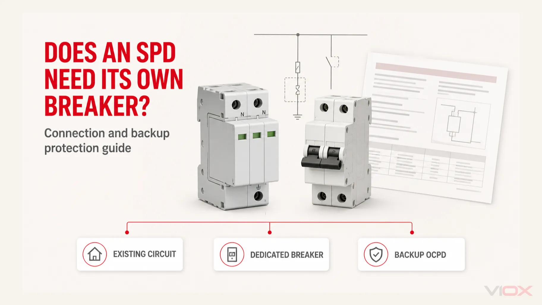
Sometimes—but only when the exact surge protective device (SPD) instructions, the existing overcurrent protective device (OCPD), the conductor and terminal ratings, and the applicable installation rules all permit it. A dedicated breaker is often the clearest way to connect and isolate a panel-mounted SPD, but it is not a universal requirement.
For an IEC-oriented DIN-rail SPD, the question is often different: does the upstream fuse or breaker already satisfy the manufacturer’s maximum backup-protection condition, or must a separate backup fuse or breaker be added? That decision cannot be made from SPD Type or surge-current rating alone.
Key Takeaways
A breaker used as the SPD’s connection point is not automatically the same as the manufacturer’s required backup OCPD.
The SPD’s internal thermal disconnector protects against abnormal heating or end-of-life behavior; it does not automatically provide branch-conductor overcurrent protection.
A suitable existing branch circuit is permitted for some products, but only when the exact instructions and all conductor, terminal, panel, and OCPD conditions are met.
Never use a universal “SPD breaker size.” The required device, rating, poles, characteristic, and short-circuit coordination are model- and installation-specific.
Panel work and SPD connections should be designed and completed by qualified personnel under the applicable local rules.
First Separate the Three Meanings of “SPD Breaker”
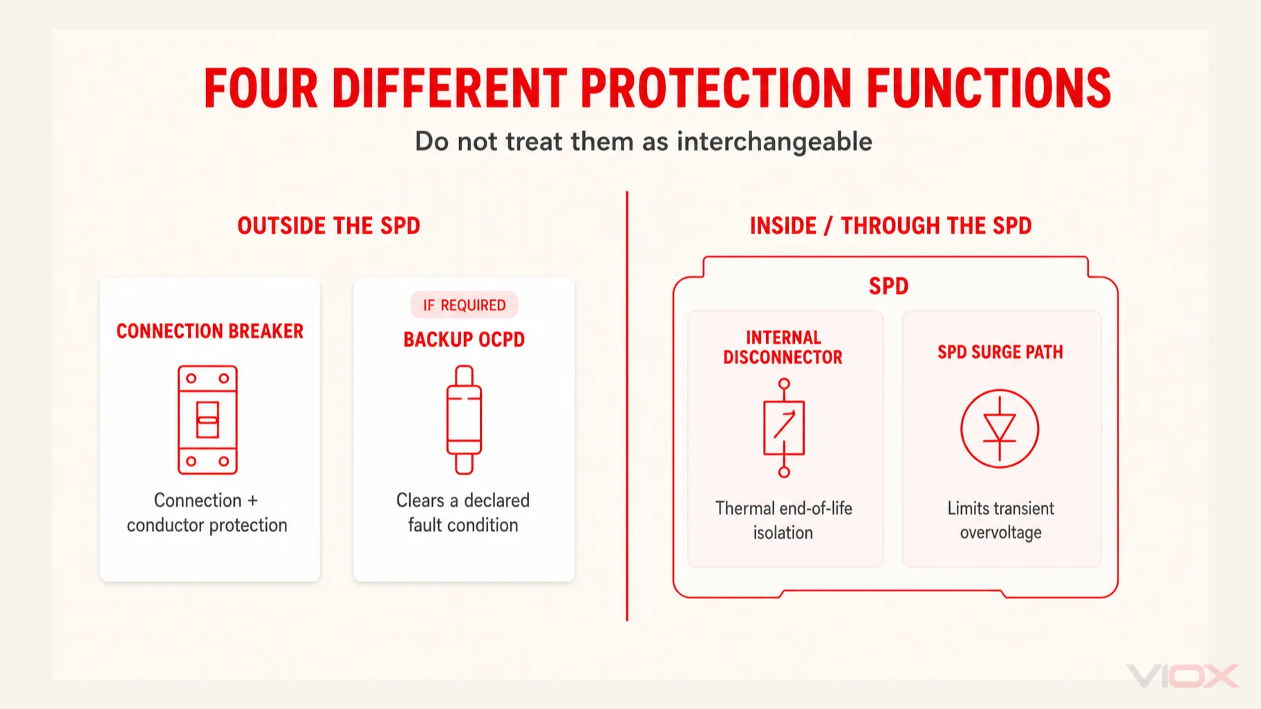
The question becomes much easier once three different functions are separated.
Function
What it does
What must prove suitability
Connection breaker or branch OCPD
Provides a connection point and may protect the SPD branch conductors; it can also provide isolation
SPD instructions, conductor ampacity, terminal ratings, panel compatibility, and local installation rules
External backup fuse or breaker
Clears a fault involving the SPD or its branch when the upstream protection alone does not meet the product’s declared condition
Exact manufacturer backup-protection table, short-circuit declaration, upstream OCPD, and coordination study
Internal SPD disconnector
Disconnects a failed or overheated protective component inside the SPD
Product construction and its evaluated or declared internal protection—not an assumption about external conductors
This distinction matters because an SPD normally operates as a shunt device: it draws negligible current in normal service and carries surge current only during a transient. Its external OCPD is therefore not selected like the breaker for a continuous load, and it is not expected to interrupt the surge before the SPD operates.
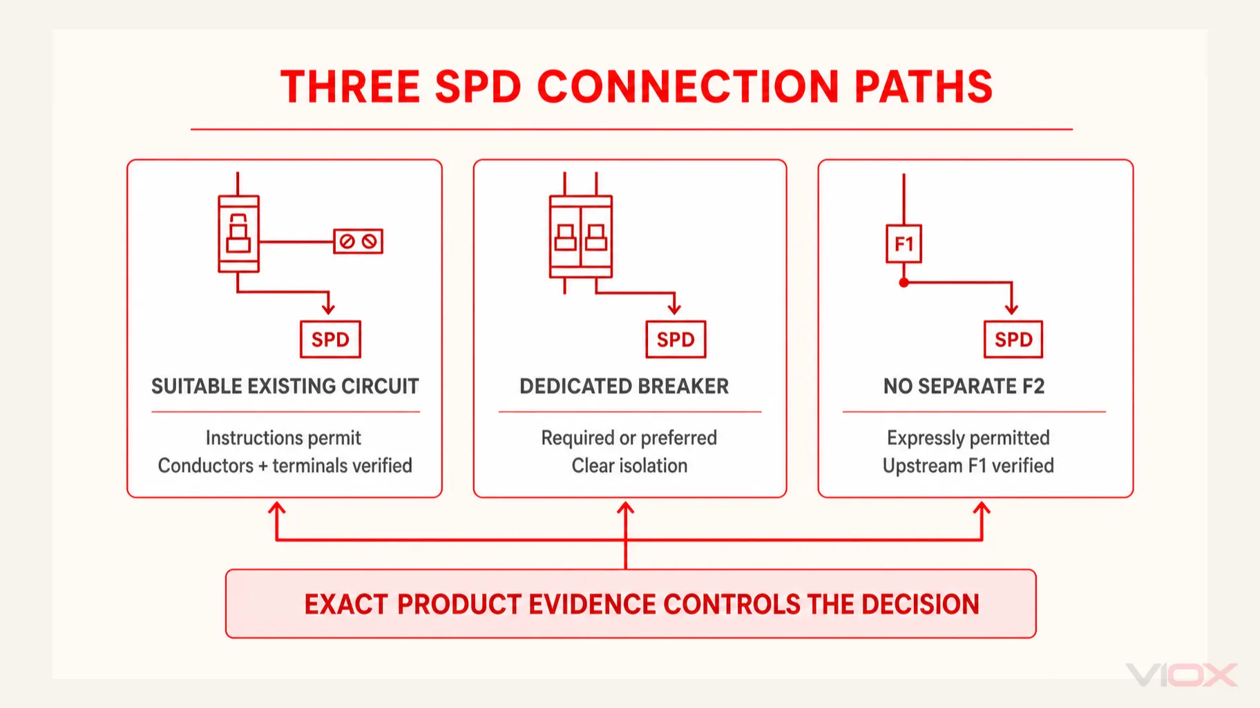
The Three Acceptable Decision Paths
Proposed path
It may be acceptable when
Reject or redesign when
Suitable existing branch circuit
The exact SPD instructions allow it; the existing OCPD and circuit remain suitable; SPD conductors have adequate ampacity; every termination is authorized; isolation and loss-of-protection consequences are acceptable
The instructions require a dedicated circuit; the terminal is not identified for the conductors proposed; conductor protection is inadequate; opening the shared breaker would unknowingly remove critical surge protection
Dedicated breaker or fuse
The product calls for it, a clear isolation point is required, a separate branch simplifies conductor protection, or the panel arrangement supports a shorter and more direct connection
The selected OCPD conflicts with the product’s tested or declared configuration, has inadequate interrupting capability, or creates excessive connection length without an engineered solution
No separate branch OCPD
The exact Type 1, integral, bus-connected, or IEC branch arrangement expressly permits it and upstream protection plus conductor rules satisfy all stated conditions
The decision is based only on “Type 1,” an internal thermal disconnector, or a high SCCR/Isccr; external conductors or the assembly still require protection
The correct output is not merely “yes” or “no.” It is a documented path tied to one exact SPD model, one distribution assembly, and one upstream protective arrangement.
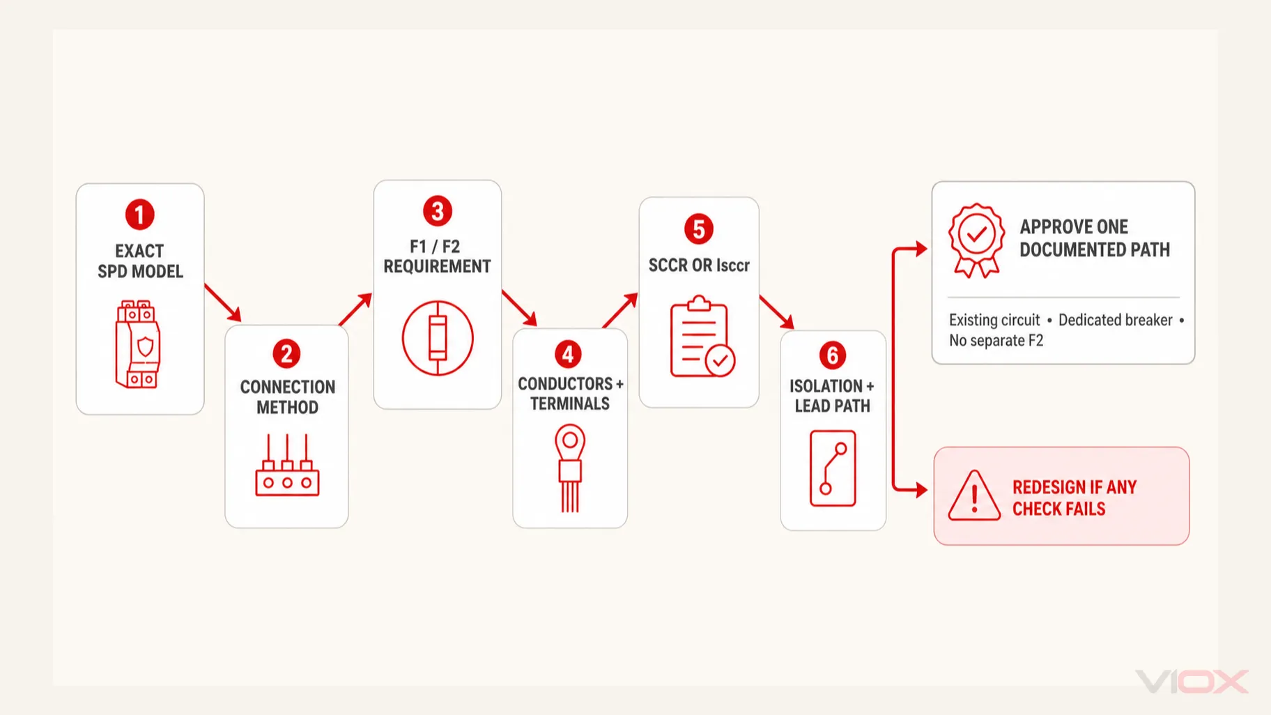
Seven Checks Before Reusing an Existing Breaker
1. Identify the SPD Type and permitted connection location
Type changes where a device may be installed, but it does not complete the breaker decision. In North American terminology, a Type 1 SPD can be installed on either side of the service overcurrent disconnect within its permitted application; a Type 2 SPD is installed on the load side. Eaton’s published SPD guidance notes that Type 1 devices may be applied without a dedicated fuse or breaker for the SPD function, while Type 2 devices may or may not require one. The exact product instructions and installation rules remain controlling.
That does not mean every Type 1 device may be connected directly to any bus. The conductors, enclosure or assembly, disconnecting method, and exact installation instructions still control. See the Type 1 vs Type 2 vs Type 3 SPD guide for classification; keep the present decision focused on the connection and backup protection.
2. Read the exact connection diagram and OCPD statement
Do not approve the connection from a catalog headline or a similar model’s manual. Obtain the current instruction sheet for the exact catalog number and record:
whether a dedicated or suitable existing branch circuit is allowed;
required or maximum OCPD type and rating;
permitted poles and system configurations;
conductor range, insulation rating, and terminal torque;
whether a backup fuse or breaker was part of the declared short-circuit condition;
whether an integral disconnector or fuse changes the external requirements.
For example, Schneider Electric states for one externally mounted SPD family that the assembly can use either a dedicated branch circuit or a suitable existing branch circuit. That is evidence for that named product family—not a universal rule for every whole-building SPD.
3. Verify the existing breaker and panel as an assembly
The proposed breaker must be permitted for the panelboard or switchboard and suitable for the system voltage, poles, interrupting duty, and application. An available empty breaker is not automatically a compatible one.
If the plan places more than one conductor in a breaker terminal, the terminal must be specifically identified for that number, material, and size of conductors. Do not treat “sharing a breaker” as permission to double-tap a terminal that is marked for one conductor. A listed distribution block, an approved pigtail arrangement, or another method may be required, but the exact solution belongs in the panel and product documentation—not in a generic SPD article.
4. Check conductor protection and termination limits
When a manufacturer permits an existing branch circuit, the SPD conductors still need adequate ampacity for the existing OCPD and must fit every terminal used. Schneider’s guidance for a particular externally mounted assembly, for example, requires the SPD conductors on an existing branch circuit to have ampacity not less than the OCPD setting.
This is why a generic breaker-size table is unsafe. Two SPDs with similar surge ratings can use different lead sizes, terminal ranges, OCPD conditions, and listing or declaration details.
5. Compare available fault current with SCCR or Isccr
For UL-oriented equipment, the SPD’s short-circuit current rating (SCCR) must not be lower than the available fault current at its connection point. Eaton’s Bussmann application guide also notes that when a specific OCPD was used to obtain the SPD’s UL short-circuit condition, the installed OCPD must match the documented type and rating.
For IEC products, verify the applicable short-circuit withstand/current declaration, often shown as Isccr, together with the manufacturer’s stated backup protective device. SCCR and Isccr are not surge-current ratings: do not substitute In, Imax, or Iimp for short-circuit coordination.
The SPD datasheet guide explains these declarations and the other ratings that must be checked before procurement.
6. Decide whether shared isolation is operationally acceptable
If the SPD shares an existing branch OCPD, opening or tripping that device may remove both the load and its surge protection. Conversely, an SPD fault could interrupt the shared circuit. That may be unacceptable for a critical control panel, process line, data system, fire/life-safety interface, or other installation where protection status must be independently monitored and restored.
A dedicated breaker can make isolation and maintenance clearer, but this is an operational advantage—not proof that one is always required.
7. Protect the installation performance
Adding an OCPD or moving the SPD to a convenient spare circuit can increase lead length and inductance. The resulting installation can have a higher let-through voltage than the device-only test value suggests. Keep connections short and direct within the product instructions and applicable rules; avoid loops and unnecessary bends.
The SPD wiring guide owns the full phase, neutral, PE, backup-protection, lead-routing, and commissioning workflow. This page determines which connection path should enter that design.
When a Dedicated Breaker Is the Better Decision
Use a dedicated breaker or fuse when the exact product instructions require it. It is also commonly preferred when it provides:
unambiguous conductor protection;
a clearly labeled isolation point for inspection or replacement;
independent service continuity for other circuits;
a practical short and direct SPD connection;
a documented OCPD that matches the product’s tested or declared condition;
cleaner panel schedules and maintenance records.
Do not choose its rating from the SPD’s kA surge-current capacity. The branch or backup OCPD must be selected from the manufacturer instructions, conductor requirements, fault-current study, and applicable installation rules.
A manufacturer-specific number can be useful evidence. Schneider, for example, recommends a 20 A or 30 A two-pole breaker for certain HEPD models. That number must not be copied to a VIOX DIN-rail SPD, an industrial switchboard SPD, or even another Schneider family without its own instructions.
IEC Installations: Compare Upstream F1 with the Declared Backup Limit
In many IEC-oriented shunt-connected SPD applications, the design uses this logic:
Identify the upstream system fuse or breaker, F1.
Find the exact SPD manufacturer’s maximum permissible backup fuse or breaker and any required device class or characteristic.
If F1 satisfies the manufacturer’s stated condition, a separate branch backup device F2 may be unnecessary for that exact arrangement.
If F1 exceeds the permitted limit—or the instructions otherwise require a branch device—select F2 according to the manufacturer data, fault level, conductor protection, selectivity, and impulse-current withstand.
Phoenix Contact illustrates this product-specific approach in its backup-fuse guidance: whether F2 is needed depends on F1, the selected SPD, and the manufacturer’s maximum backup-fuse value. The guide also warns that an added fuse that lacks sufficient impulse withstand can open during a surge and leave the installation unprotected.
This is the correct level of generalization. It explains the decision without turning one manufacturer’s fuse values into an industry-wide table. IEC 61643-12:2020 covers AC SPD selection and application principles and includes disconnecting-device information; the exact product declaration completes the design.
Two Bounded Examples
Example A: externally mounted panel SPD in North America
The manufacturer instructions permit either a dedicated branch circuit or a suitable existing one. Before reusing an existing breaker, the designer verifies that:
the SPD Type and installation location are permitted;
the breaker and panel are compatible;
the existing OCPD does not exceed the ampacity of the SPD conductors;
the proposed termination is identified for all conductors used;
available fault current does not exceed the SPD’s SCCR under the documented OCPD condition;
sharing the circuit will not create an unacceptable loss-of-protection condition;
connection length remains within the manufacturer’s installation guidance.
If one check fails, the answer is not “use a larger breaker.” Use a dedicated compatible path or select a different SPD/assembly arrangement.
Example B: DIN-rail Type 2 SPD in an industrial IEC panel
The datasheet states a maximum permissible upstream backup fuse and an Isccr condition. The project compares the installed F1 with that declaration. If F1 is within the permitted condition and the manufacturer allows omission of F2, the SPD branch may not need a separate backup fuse. If F1 exceeds the limit, F2 is required and must match the declared device type/rating while coordinating with fault current, conductors, and surge impulse duty.
Neither example produces a universal breaker size. Both produce a traceable approval record.
SPD Breaker and Backup-Protection Approval Checklist
Required evidence
Acceptance question
Record
Exact SPD catalog number
Is the instruction sheet for this precise model and revision?
Model/revision
System and SPD Type
Is the connection location permitted?
Type and location
Manufacturer connection method
Existing branch, dedicated branch, direct/integral, or another declared arrangement?
Selected path
Upstream OCPD F1
What device, rating, characteristic/class, poles, voltage, and interrupting rating are installed?
F1 details
Required backup OCPD F2
Is F2 required, optional, integrated, or expressly unnecessary under stated conditions?
F2 decision
Conductors and terminals
Are ampacity, material, size, temperature rating, quantity per terminal, and torque all permitted?
Verified values
Fault-current coordination
Is available fault current within SCCR or the applicable IEC declaration such as Isccr?
Study and declaration
Panel or assembly compatibility
Are the breaker, accessories, and termination method authorized?
Manufacturer evidence
Isolation and monitoring
Can the SPD be safely isolated, and will loss of protection be visible or remotely indicated?
Operating method
Connection path
Are leads short, direct, and compliant with the exact instructions?
Drawing/reference
Applicable rules
Has the design been checked for the project jurisdiction and assembly standard?
Reviewer/approval
Do not release the installation or purchase order while any required row is “assumed.”
Frequently Asked Questions
Does a whole-house surge protector need its own breaker?
Not always. Many panel-mounted Type 2 products use a dedicated two-pole breaker, but some exact products permit a suitable existing branch circuit or another listed connection. Follow the specific SPD and panel instructions rather than a universal rule.
Can an SPD be connected to the main breaker?
Do not place SPD conductors under main-breaker terminals unless the complete assembly and product documentation expressly permit that connection. Type 1 suitability does not by itself authorize an improvised main-terminal tap. Service-side work may also require utility coordination and jurisdiction-specific approval.
Can a Type 1 SPD be installed without a dedicated breaker?
Some Type 1 SPDs are evaluated or declared for installation without a dedicated fuse or breaker. External conductors and the distribution assembly may still require an approved protection or tap arrangement. Verify the exact instructions, SCCR condition, and applicable rules.
What size breaker should I use for an SPD?
Use the breaker or fuse type and rating stated for the exact SPD and installation. If the instructions provide only a maximum value, the final selection must also protect the conductors, satisfy fault-current and coordination requirements, and withstand the relevant surge impulse. SPD kA ratings do not directly determine breaker amperage.
Can two wires be connected to one breaker for an SPD?
Only when the breaker terminal is specifically identified for the number, material, and size of conductors proposed and the SPD instructions allow the circuit arrangement. Otherwise use an approved connection method designed for the assembly; do not improvise a double tap.
Does the breaker protect connected equipment from the surge?
No. The SPD limits transient overvoltage and diverts surge current. The breaker or fuse provides overcurrent protection and isolation according to its design. These devices perform different, coordinated functions.
Final Decision
An SPD may use an existing breaker only after the exact product and installation evidence proves that path suitable. Choose a dedicated breaker when the instructions require one or when it provides the necessary conductor protection, isolation, and operating clarity. For IEC designs, compare upstream F1 with the manufacturer’s maximum backup-protection declaration before deciding whether F2 is required.
For an industrial SPD quotation, provide VIOX with the single-line diagram, system voltage and earthing arrangement, SPD Type, available fault current, upstream OCPD, proposed connection method, required backup protection, and panel constraints. Review VIOX surge protective devices only after those inputs are defined.
This article supports specification and design review. It is not an energized-work or DIY panel-installation procedure. Final work must follow the exact equipment instructions, the applicable installation rules, and qualified engineering or electrical review.
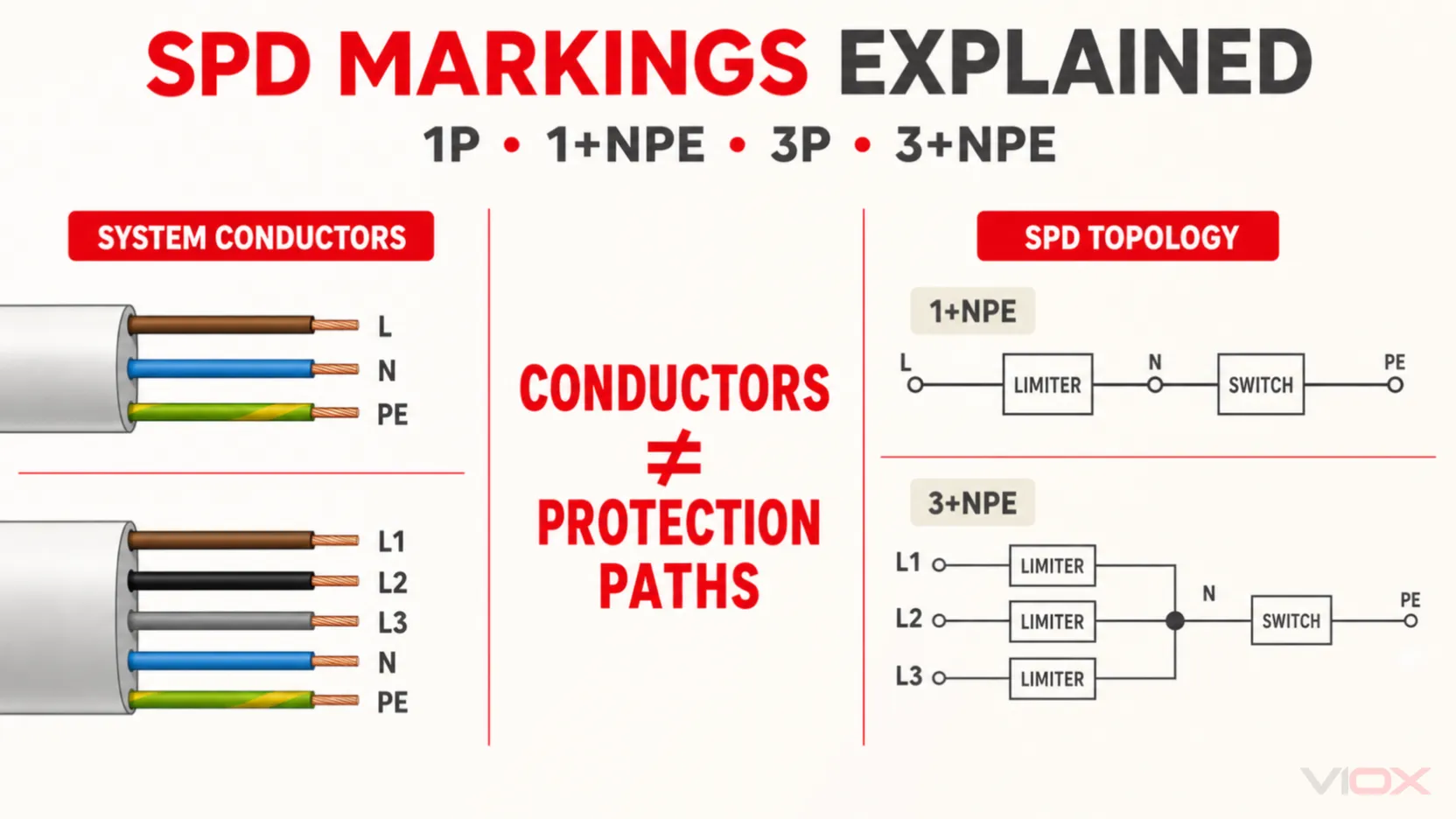
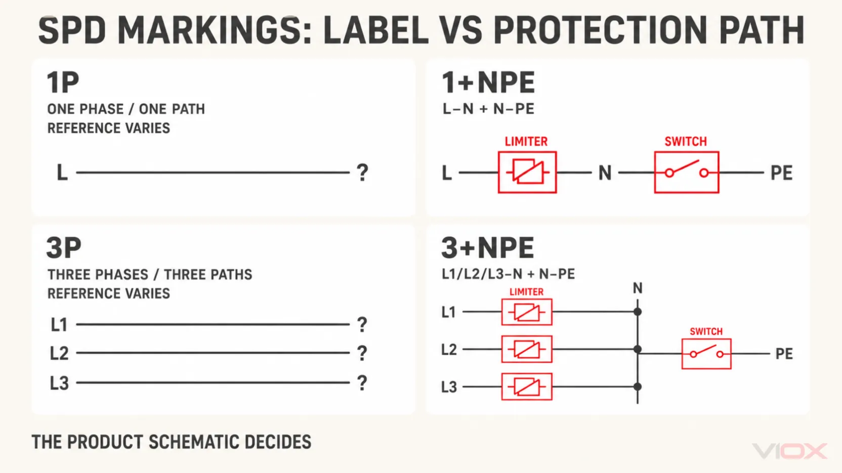
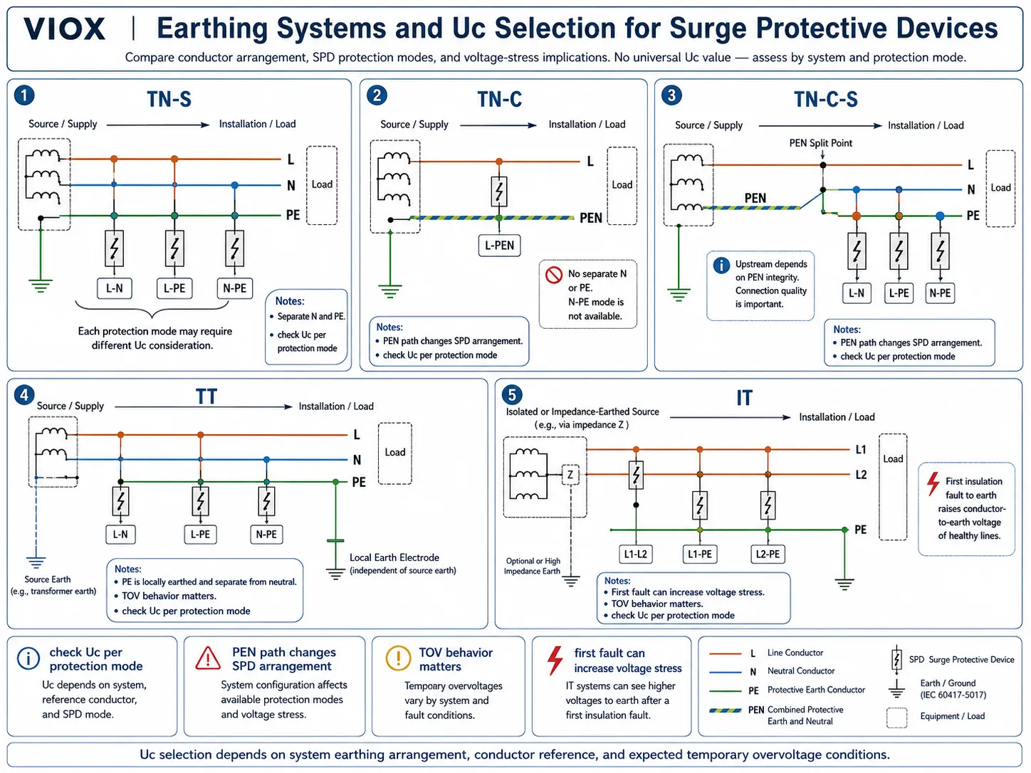
3P+N+PE and 3+NPE do not necessarily mean the same thing. In a cable schedule or single-line diagram, 3P+N+PE usually describes five conductors: three phases, neutral and protective earth. On a surge protective device (SPD), 3+NPE or 3+1 commonly describes an internal protection topology: three line-to-neutral protection paths plus one neutral-to-earth discharge path.
The same distinction applies to 1P+N+PE and 1+NPE. One describes the conductors in the circuit; the other commonly describes how surge-protection elements are connected. Because manufacturer abbreviations vary, the SPD circuit diagram and declared modes of protection always take priority over the short label.
Scope: This guide uses IEC-oriented terminology for low-voltage AC installations. UL 1449 product categories, North American service configurations and manufacturer-specific MCOV markings require a separate selection check. Photovoltaic DC, battery DC and specialized IT applications are outside the simple rules in this article.
Key Takeaways
1P+N+PE normally describes one phase, neutral and protective earth; 3P+N+PE normally describes three phases, neutral and protective earth.
1+NPE or 1+1 on an SPD commonly means one L-N protection path plus one N-PE element.
3+NPE or 3+1 commonly means three L-N paths plus one N-PE element.
1P and 3P are not universal SPD circuit definitions. They may describe protected conductors, cartridges, poles or a manufacturer’s product family.
Earthing system alone is not enough. Selection also depends on system voltage, neutral availability, PE or PEN arrangement, installation position and required modes of protection.
SPD topology, SPD Type and electrical ratings are separate decisions.
Never select an SPD from a fixed kA, voltage or conductor-size rule without checking the applicable installation standard and exact manufacturer instructions.
Quick Comparison: What Do the Markings Mean?
Marking
Where it is commonly seen
Usual meaning
What it does not prove
1P
Product catalog, panel schedule or single-phase equipment description
One phase or one protected pole/path, depending on context
It does not identify whether the SPD is connected L-N or L-PE
1P+N+PE
Cable schedule, connector description or wiring diagram
One phase, one neutral and one protective-earth conductor
It does not specify the SPD’s internal protection elements
1+NPE, 1+1
SPD topology or product description
Commonly one L-N voltage-limiting path plus one N-PE discharge path
It does not by itself establish Type, voltage rating or discharge-current capability
3P
Product catalog or three-phase equipment description
Three phases or three protected paths, depending on context
It does not prove whether the reference is N, PE or PEN
3P+N+PE
Cable schedule or electrical system diagram
Three phases, neutral and PE: normally five conductors
It is not automatically the same as an SPD marked 3+1
3+NPE, 3+1
SPD topology or product description
Commonly three L-N paths plus one N-PE discharge path
It does not prove that the topology suits every TN-S, TT or IT installation
The table is a decoding aid, not a replacement for the product schematic. Some manufacturers use 1N, 3N, 3P+N, 1+1, 3+1 or other abbreviations for similar commercial configurations. Confirm the terminals and internal diagram before procurement or installation.
3P+N+PE Meaning: A Conductor Description, Not an SPD Rating
In an electrical supply description, 3P+N+PE normally means:
3P: L1, L2 and L3;
N: neutral;
PE: protective earth.
This is normally a five-conductor arrangement. It tells the designer which conductors are present, but not how an SPD should be connected among them.
Likewise, 1P+N+PE normally means:
one phase conductor;
one neutral conductor;
one protective-earth conductor.
That is normally a three-conductor single-phase circuit. It still does not tell you whether the intended SPD is 1+1, 2+0 or another manufacturer-defined configuration.
This distinction matters for search terms such as 3npe, 3ph+n+pe and 1/n/pe meaning. The letters may describe a supply, cable, connector, socket or SPD. Identify the object and inspect its diagram before applying an SPD topology rule.
What 1+NPE and 3+NPE Commonly Mean on an SPD
1+NPE or 1+1 topology
A typical single-phase 1+1 arrangement contains:
one protection element between line and neutral; and
one protection element between neutral and protective earth.
The L-N element is commonly voltage-limiting technology, while the N-PE element is commonly a voltage-switching device. This arrangement provides a direct path for limiting line-to-neutral differential voltage and a coordinated path from neutral to earth during the surge.
Do not describe this as “line, neutral and earth are all protected.” PE is not a load conductor that the SPD protects in the same way as a phase. It forms part of the surge-current discharge and equipotential-bonding path.
Generic concept:
L ───── [L-N protection element] ───── N
                                         |
                                 [N-PE element]
                                         |
                                        PE
ABB’s global SPD guide lists 1+1 and 3+1 as protected-line configurations and separately maps product arrangements to TN-C, TN-S and TT networks. That is a useful reminder that the number describes protection architecture—not a universal quality grade or surge-current rating.
The exact internal technology is manufacturer-specific. Verify the declared protection modes, temporary-overvoltage behavior and, where a voltage-switching element is used, the power-frequency follow-current capability.
Why 1P and 3P Labels Are Not Enough
An SPD is connected in parallel with the supply; it does not normally switch the load conductors like a circuit breaker. As a result, “pole” can be less precise on an SPD than it is on an isolating or overcurrent device.
Depending on the manufacturer, 1P or 3P may refer to:
the number of protected phase conductors;
the number of cartridges;
the number of protection paths;
the DIN-rail module count;
or a product-family description.
A three-pole label therefore does not prove whether the internal paths are L-N, L-PE or L-PEN. A four-module device does not automatically provide the same circuit as a 3+1 assembly. Use the product schematic to answer three questions:
Which terminals are connected during a surge?
Which protection modes are declared: L-N, L-PE, N-PE, L-PEN or L-L?
Which voltage and current ratings apply to each mode or complete assembly?
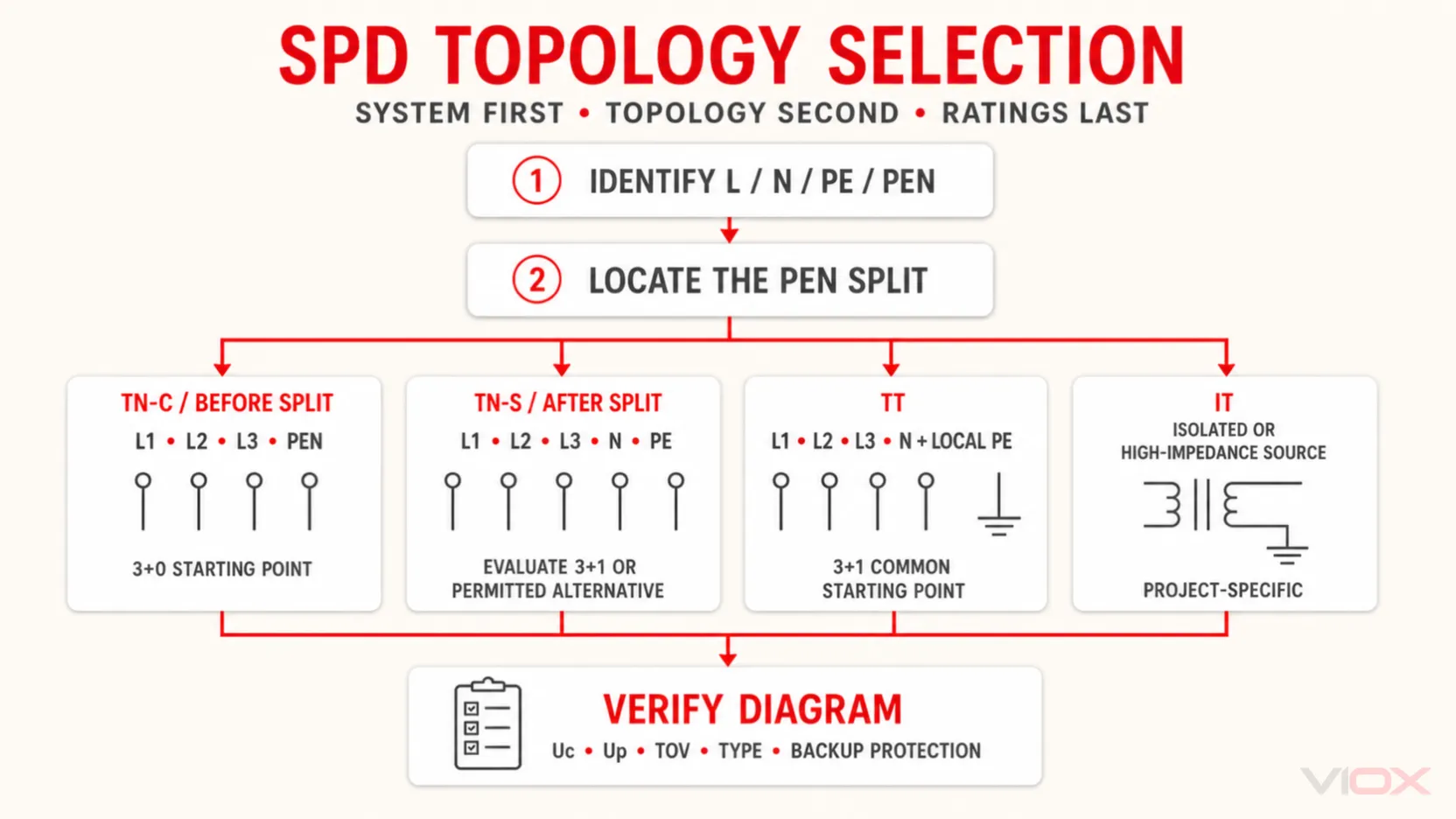
Start Selection With the System at the Exact Installation Point
The correct first question is not “Is the supply single phase or three phase?” It is:
Which live, neutral and protective conductors exist where this SPD will be installed, and how are they earthed?
Record all of the following:
nominal and maximum continuous system voltage;
AC system configuration;
whether neutral is distributed;
whether the protective conductor is PE or combined PEN;
whether the SPD is before or after a PEN separation point;
the earthing system at that exact location;
the installation level: origin, main board, sub-distribution or near the equipment;
the required common-mode and differential-mode protection.
Earthing-system decision table
System and location
Conductors at the SPD
Common topology starting point
Required caution
TN-C
L1/L2/L3 and PEN
Commonly 3+0, with phase-to-PEN paths
There is no separate N-PE path while N and PE remain combined
TN-C-S before PEN separation
L1/L2/L3 and PEN
Treat as the TN-C section
Identify the separation point rather than relying on the utility label alone
TN-C-S after PEN separation
L1/L2/L3, N and PE
Treat as TN-S; evaluate 3+1 or another permitted topology
N and PE must remain separate downstream of the defined bonding point
TN-S
L1/L2/L3, N and PE
3+1 or another topology allowed by the design and local rules
Required common- and differential-mode protection must be defined
TT
L1/L2/L3, N and local PE
3+1 is a common starting architecture
SPD/RCD position, N-PE element and failure behavior require verification
IT
Varies; neutral may be absent or distributed
Project-specific
First-fault voltage-to-earth and TOV conditions can invalidate a generic TN/TT rule
ABB’s guidance illustrates different common-mode and differential-mode arrangements for TN-C, TN-S and TT systems rather than applying one configuration to all networks. The applicable national adoption of IEC 60364, the project single-line diagram and the SPD manufacturer’s instructions remain controlling.
Typical Single-Phase and Three-Phase Wiring Concepts
These diagrams show topology only. They do not specify fusing, RCD position, conductor size, terminal torque or a complete compliant installation.
Single-phase 1+1 concept
Incoming L ───────┬──────────── Load L
                  │
              [L-N element]
                  │
Incoming N ───────┼──────────── Load N
                  │
              [N-PE element]
                  │
PE / bonding bar ─┴──────────── Equipment PE
This is a common concept for a single-phase circuit with separate N and PE. It must not be applied where the product voltage, earthing arrangement or local installation rules require a different configuration.
Three-phase 3+1 concept for suitable TN-S or TT applications
This topology provides direct L-N paths and one N-PE path. It is commonly encountered in TN-S and TT product selections, but “TN-S” or “TT” alone does not complete the specification.
At a TN-C point, neutral and protective functions are combined in PEN. Adding an independent N-PE path is not meaningful when separate N and PE conductors do not exist there.
SPD Topology Is Separate From Type 1, Type 2 and Type 3
1+1, 3+0 and 3+1 describe protection connections. Type 1, Type 2 and Type 3 describe test classification and application role. A 3+1 assembly can be Type 1, Type 2 or combined Type 1+2 if the manufacturer has designed and tested it accordingly.
SPD classification
Principal IEC test quantity
Typical role in a coordinated concept
Type 1 / Class I tested
Impulse current Iimp, using a 10/350 μs current waveform
Lightning-current protection where the risk assessment, external lightning protection system, incoming service or national rules require it
Type 2 / Class II tested
Nominal and maximum discharge current using an 8/20 μs current waveform
Distribution-level protection against induced lightning and switching transients
Type 3 / Class III tested
Combination-wave testing using a 1.2/50 μs voltage impulse and 8/20 μs current impulse
Supplementary protection close to sensitive equipment as part of coordinated protection
Do not convert this table into the rule “every service entrance needs a 100 kA Type 1 SPD.” SPD Type and discharge-current capability must follow the actual lightning risk, incoming services, installation design, national requirements and manufacturer coordination data.
Correct topology is necessary, but it is only the first part of the specification.
Parameter
What it tells you
Selection boundary
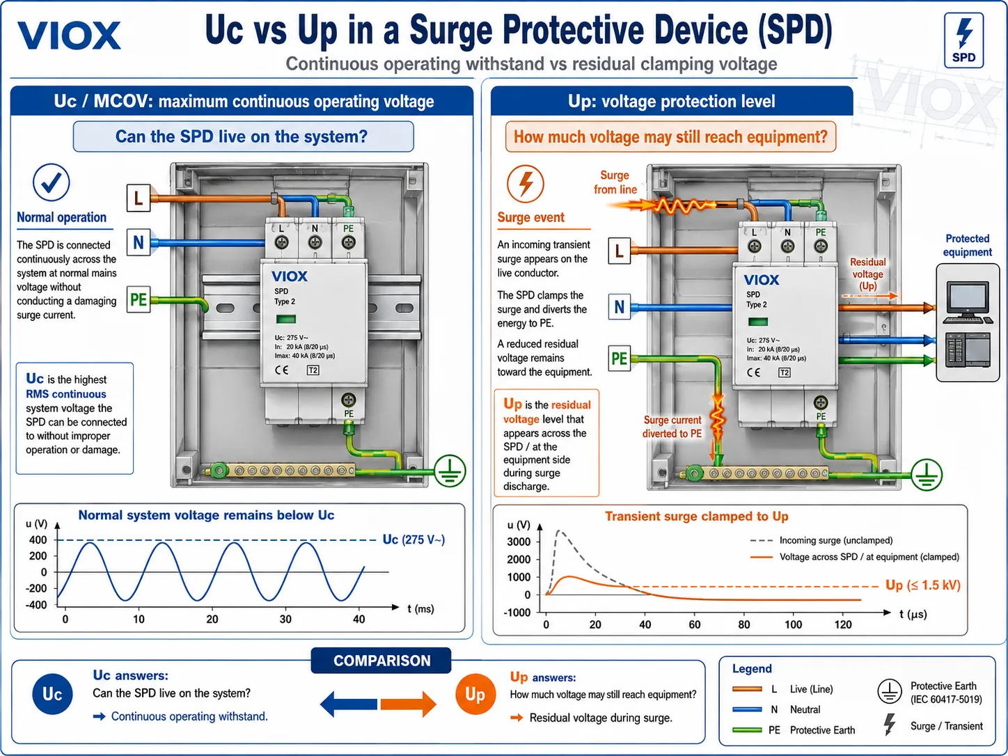
Uc
Maximum continuous operating voltage across the relevant SPD terminals
Must suit the actual system voltage, protection mode and earthing arrangement
Up
Declared voltage protection level under specified test conditions
Must be coordinated with equipment impulse withstand and installation voltage drop
Iimp
Impulse discharge-current rating associated with Type 1 testing
Relevant when lightning-current duty is required
In
Nominal discharge current, normally based on the 8/20 μs waveform
Used to compare declared repetitive discharge performance within the product standard
Imax
Maximum discharge current for a Type 2 SPD under stated 8/20 μs conditions
Not a universal indication of service life or installation suitability
TOV
Temporary-overvoltage withstand or behavior
Must reflect power-frequency overvoltages possible in the specific network and fault condition
Ifi
Follow-current interrupting capability where applicable
Important for voltage-switching elements that may conduct power-frequency follow current
Short-circuit rating or behavior
Ability to coordinate safely with prospective short-circuit current and disconnection
Verify terminology, declared value and required backup protective device from the exact datasheet
There is no universal rule that 275 V Uc is correct for every 120/240 V or 230/400 V installation. Uc must be checked for the voltage appearing across each protection mode, including abnormal conditions considered by the applicable standard and manufacturer.
An SPD may include internal thermal disconnection, but external short-circuit protection may still be required. The permitted fuse or circuit-breaker arrangement depends on:
the SPD design;
available prospective short-circuit current;
upstream overcurrent protection;
manufacturer coordination tables;
and the applicable installation standard.
Do not assign a fixed fuse or breaker to every SPD with the same Type label or discharge-current rating.
Keep connections short and direct
The inductive voltage developed along SPD connection conductors adds to the voltage seen by the protected equipment. Avoid long, looped or unnecessarily separated line and earth connections. Use the topology and routing method permitted by the manufacturer and local rules.
Size conductors from installation requirements—not a universal AWG table
Connection conductor cross-section depends on the SPD Type, product terminals, backup protection, fault-current conditions, installation standard and manufacturer instructions. A generic progression such as 12 AWG for one Type and 8 AWG for another should not be presented as a global requirement.
Coordinate protection stages
One SPD at the origin may not produce the required effective protection level at remote equipment. Cable length, the first SPD’s Up, the equipment impulse withstand and coordination with downstream SPDs all affect the result. Use the manufacturer’s coordination data rather than combining unrelated SPDs solely by Type label.
Determine whether 3P+N+PE describes a cable, connector, power system or SPD. Do not interpret a conductor label as an internal protection circuit.
Step 2: Record the system voltage
Use the nominal voltage, expected continuous operating range and relevant fault/TOV conditions. Avoid selecting Uc from nominal voltage alone.
Step 3: Identify N, PE and PEN at the installation point
Verify whether neutral is distributed and whether protective and neutral functions are separate or combined. In TN-C-S, locate the PEN separation point.
Step 4: Confirm the earthing system
Identify TN-C, TN-S, TN-C-S, TT or IT from the actual single-line diagram. Do not infer it only from conductor colors or the number of terminals in a panel.
Step 5: Define the required protection modes
List the voltage stresses that must be limited: L-N, L-PE, N-PE, L-PEN and, where relevant, L-L. This step turns a vague “pole count” request into an engineering requirement.
Step 6: Select a topology starting point
Evaluate 1+1, 3+0, 3+1, 4+0 or another manufacturer-supported circuit. Confirm it from the schematic, not only the sales description.
Step 7: Select Type and electrical ratings
Determine Type 1, Type 2, Type 3 or a combined classification from the installation role and risk. Then verify Uc, Up, discharge-current ratings, TOV behavior, follow-current capability and short-circuit coordination.
The first commonly describes five system conductors. The second commonly describes an SPD topology. Confusing them can produce the wrong protection path.
Saying that earth is “protected” as another pole
PE is part of the protective bonding and surge-current path. It is not an ordinary active conductor to be described as protected in the same way as L or N.
Selecting from single phase versus three phase alone
Phase count does not reveal whether N exists, whether the reference conductor is PE or PEN, or whether the installation is before or after a PEN split.
Assuming every TN-S or TT system uses the same SPD
3+1 is a common architecture, but voltage, Type, protection mode, RCD position, TOV behavior, fault current and local rules still have to match.
Using one fixed Uc, kA rating or conductor size globally
These values are product- and system-dependent. A number that is appropriate for one voltage system or manufacturer series may be wrong for another.
Ignoring the circuit diagram
Commercial abbreviations are not fully standardized across manufacturers. The declared terminal diagram and modes of protection are the final evidence of the topology.
Specification Checklist
Before approving an SPD, record:
system voltage and frequency;
AC or DC application;
conductor arrangement at the SPD location;
TN-C, TN-S, TN-C-S, TT or IT system;
position relative to the PEN split and residual current device;
required L-N, L-PE, N-PE, L-PEN and L-L modes;
selected topology and manufacturer circuit diagram;
Type 1, Type 2, Type 3 or combined classification;
Uc, Up, Iimp, In, Imax, TOV and any applicable Ifi;
prospective short-circuit current and declared SPD short-circuit behavior;
required backup fuse or circuit breaker;
connection routing and conductor requirements;
applicable product certification and national installation rules.
Only after this checklist is complete should the designer compare product models. For product-family evaluation, review the VIOX surge protective device range and provide the single-line diagram and system data with the inquiry.
Frequently Asked Questions
What does 3P+N+PE mean?
In an electrical system, cable or connector description, 3P+N+PE normally means three phase conductors, one neutral conductor and one protective-earth conductor. It normally describes five conductors. It does not by itself specify the internal topology of an SPD.
Is 3P+N+PE the same as 3+NPE on an SPD?
No. 3P+N+PE usually describes the conductors present in the system. 3+NPE or 3+1 commonly describes three L-N protection paths plus one N-PE protection element inside an SPD. Always verify the product schematic.
What does 1P+N+PE mean?
It normally means one phase, one neutral and one protective-earth conductor. This describes a typical three-conductor single-phase circuit, not necessarily a 1+1 SPD topology.
What is a 1+NPE SPD?
A 1+NPE or 1+1 SPD commonly contains one L-N voltage-limiting path and one N-PE discharge path. Exact technology, ratings and permitted systems depend on the product.
What is a 3+NPE SPD?
A 3+NPE or 3+1 SPD commonly contains three L-N protection paths and one N-PE path. It is frequently used as a starting topology for suitable three-phase TN-S and TT applications, subject to the exact network and installation rules.
Does NPE mean the earth conductor carries normal current?
No. PE should not carry normal load current. The N-PE element provides a surge-current path under transient conditions and must behave according to its declared design and system requirements.
Is a 3+1 SPD always better than a 3+0 SPD?
No. They fit different conductor and earthing arrangements. A TN-C point with PEN commonly leads to a 3+0 architecture, while a system with separate N and PE may require 3+1 or another permitted topology.
Can I select an SPD only from the number of poles?
No. Pole count does not fully define the protection modes, Type, voltage rating, discharge-current rating, TOV behavior or short-circuit coordination. Inspect the schematic and datasheet.
What is the difference between SPD topology and SPD Type?
Topology describes how protection elements connect among L, N, PE or PEN. Type 1, Type 2 and Type 3 describe test classification and application role. They are independent selection dimensions.
Conclusion
The safest way to interpret 1P, 1+NPE, 3P and 3+NPE is to separate conductor notation from SPD topology. 3P+N+PE normally tells you that three phases, neutral and protective earth are present. 3+NPE or 3+1 commonly tells you how four surge-protection paths are arranged.
Neither label completes the specification. Correct SPD selection requires the system voltage, earthing arrangement, N/PE/PEN configuration, installation position, protection modes, SPD Type, electrical ratings, backup protection and manufacturer wiring instructions. When the abbreviation and circuit diagram appear to disagree, trust the verified circuit diagram and request clarification before installation.
Uc vs Up in an SPD, showing maximum continuous operating voltage during normal operation and voltage protection level during a surge event.
Uc and Up are two different voltage parameters on a surge protective device (SPD). Uc, also called maximum continuous operating voltage or MCOV, is the highest voltage the SPD can withstand continuously without operating abnormally. Up, or voltage protection level, is the voltage that may still appear across the SPD terminals during a surge test.
In simple terms, Uc tells you whether the SPD can live safely on the system, while Up tells you how well it limits surge voltage for downstream equipment.
Parameter
Full name
What it tells you
Selection risk
Uc / MCOV
Maximum continuous operating voltage
Whether the SPD can remain connected under normal system voltage and voltage variation
Too low may cause aging, heating, or disconnection; unnecessarily high Uc may reduce protection effectiveness
Up
Voltage protection level
The residual voltage level during a specified surge test
Too high may expose downstream equipment to damaging voltage
If you need the broader device background first, start with What Is a Surge Protective Device?. This article focuses specifically on the two voltage parameters that buyers, panel builders, and engineers most often misread on SPD datasheets.
What Does Uc Mean on an SPD?
Uc is the maximum continuous operating voltage of an SPD. It is the highest voltage that can be continuously applied across a specific SPD protection mode without abnormal operation.
In UL terminology, the equivalent concept is commonly called MCOV (Maximum Continuous Operating Voltage). In IEC-based datasheets, the marking is usually Uc.
Uc answers a very practical question:
Can this SPD remain connected to this system continuously without operating, overheating, aging prematurely, or disconnecting under normal voltage conditions?
Why Uc Is Not Just the Nominal System Voltage
An electrical system marked as 230 V, 400 V, 480 V, 690 V, or 1000 V DC does not stay at exactly that value in real operation. The SPD must tolerate:
normal supply voltage variation
temporary overvoltage (TOV) conditions
line-to-earth and line-to-neutral voltage differences
neutral behavior in TN, TT, and IT systems
DC open-circuit voltage in PV systems
manufacturer-defined voltage and protection mode limits
This is why an SPD is not selected by nominal voltage alone. It is selected by matching Uc to the real maximum continuous voltage that can appear across each protection mode.
What Happens If Uc Is Too Low?
If Uc is too low for the actual system, the SPD may conduct during normal operation or during normal voltage variation. That can cause:
unnecessary thermal stress
accelerated MOV aging
nuisance end-of-life indication
module disconnection
backup protection operation in severe cases
In practical terms, a too-low Uc makes the SPD behave as if ordinary system voltage is already a problem.
What Happens If Uc Is Too High?
Higher Uc is not automatically safer. If Uc is unnecessarily high, the SPD may have a higher voltage protection level and may provide less effective limitation for sensitive equipment.
The correct approach is not "choose the highest Uc available." It is:
choose the lowest Uc that is still suitable for the system voltage, earthing arrangement, temporary overvoltage behavior, protection mode, and manufacturer data.
Some designs apply additional margin for voltage fluctuation or temporary overvoltage, but the correct Uc must be selected according to the real system and the SPD datasheet. Avoid using a universal formula such as
Uc = 1.3 x Un
as a substitute for engineering review.
What Does Up Mean on an SPD?
Up is the voltage protection level of an SPD. It represents the voltage that appears across the SPD terminals during a specified surge test condition.
In practical language, Up is the SPD’s let-through voltage under the defined test. It answers:
When the SPD conducts during a surge event, how much voltage may still reach the downstream equipment?
An SPD does not reduce the voltage to zero. It limits the surge to a lower residual level. That residual level is what Up helps describe.
Why Lower Up Is Usually Better, But Not Always Enough
A lower Up value generally means better voltage limitation, but only when compared under the same:
SPD type
standard
voltage rating
test waveform
discharge current condition
protection mode
installation method
Comparing Up values across different SPD types or standards can be misleading. A Type 1 SPD designed for lightning-current duty and a Type 2 SPD designed for distribution-level protection may not be directly comparable just because both datasheets show a Up value.
Up Must Be Read With Installation Lead Length
The Up value is measured at the SPD terminals under standard test conditions. In a real panel, the protected equipment sees:
SPD terminal voltage + voltage added by connection leads and wiring layout
Long, looped, or poorly routed SPD conductors add inductive voltage during a surge. This can make the actual let-through voltage higher than the datasheet Up value suggests.
Not usually selected "too low," but must match device type and system
Wrong high value risk
Weaker voltage limitation for sensitive equipment
Equipment may still see damaging voltage
Related parameter
Ucpv for PV DC systems; MCOV in UL terminology
VPR in UL terminology; equipment impulse withstand voltage
Selection priority
Check first because it determines system compatibility
Check after Uc because it determines protection quality
Common mistake
Choosing by nominal voltage only
Comparing values across different test conditions
The two parameters work together. Uc must be high enough for the system; Up must be low enough for the equipment. If either side is wrong, the SPD selection is weak.
Why Uc Must Match the System Voltage
Uc is system-dependent. The same SPD may be suitable in one power system and unsuitable in another, even if both systems have similar nominal voltage.
Important factors include:
nominal AC or DC voltage
maximum expected continuous voltage
line-to-neutral and line-to-earth voltage
temporary overvoltage behavior
earthing arrangement
SPD protection mode
AC, DC, or PV-specific rating
manufacturer’s permitted wiring configuration
For AC low-voltage SPDs, IEC 61643-11 is the key IEC product standard. For photovoltaic DC-side SPDs, IEC 61643-31 is the relevant IEC framework. In North American projects, UL 1449 terminology such as MCOV and VPR may appear.
Up should be lower than the impulse withstand level of the protected equipment, with margin for installation lead voltage and coordination. The exact margin depends on the standard, equipment category, project requirements, and the protection strategy.
Avoid treating a simple formula such as
Up <= 0.8 x Uw
as a universal rule. It may be used as a design principle in some contexts, but real selection should account for:
equipment impulse withstand voltage
overvoltage category
distance between SPD and equipment
lead length and routing
upstream/downstream SPD coordination
Type 1, Type 2, or Type 3 SPD role
test condition behind the published Up value
For sensitive electronics, control panels, PLC systems, IT equipment, and EV charging electronics, Up often becomes the parameter that determines whether the protection is genuinely useful, not just installed.
How Earthing Systems Affect Uc Selection
Earthing system diagram showing how TN-S, TN-C, TN-C-S, TT, and IT arrangements affect SPD Uc selection and protection modes.
Earthing arrangement affects which conductors may experience voltage stress and which protection modes are required. This is one of the most common places where SPD voltage selection goes wrong.
System
Why it matters for Uc
Selection note
TN-S
Line, neutral, and protective earth are separated; L-PE and N-PE protection modes may be used
Check Uc for each protection mode, not only the line-to-neutral system voltage
TN-C
Neutral and protective earth are combined as PEN in part or all of the system
Do not treat it the same as TN-S without checking the exact wiring point and permitted SPD arrangement
TN-C-S
PEN is separated into N and PE at a defined point
The transition point matters; confirm the SPD wiring diagram for that location
TT
Local earth electrode impedance and neutral-to-earth behavior can influence overvoltage stress
N-PE path and Uc must be selected carefully; TOV behavior is especially important
IT
First fault condition can raise voltage stress on healthy conductors
Higher Uc may be required depending on system design and insulation monitoring strategy
PV DC
String voltage changes with temperature and open-circuit voltage
Use Ucpv and a DC/PV-rated SPD, not an AC-only Uc value
This table is a selection guide, not a replacement for local code, project design, or manufacturer wiring instructions.
AC SPD vs DC SPD vs PV SPD Voltage Parameters
Application map comparing Uc and Up selection for AC SPDs, industrial DC SPDs, and PV DC SPDs using Ucpv for solar string voltage conditions.
AC, DC, and PV SPDs use similar ideas, but the voltage parameters are not interchangeable.
SPD application
Voltage parameter to check
Main selection issue
AC low-voltage SPD
Uc or MCOV
Must match line-to-neutral, line-to-earth, line-to-line, and earthing arrangement
PV DC SPD
Ucpv or maximum continuous PV voltage rating
Must exceed the maximum PV string voltage, including cold-temperature open-circuit voltage
Industrial DC SPD
DC continuous operating voltage
Must match polarity, fault behavior, and system insulation arrangement
Signal SPD
Maximum operating voltage for the signal interface
Must not disturb communication, bandwidth, or measurement accuracy
For solar systems, nominal DC voltage is not enough. PV string open-circuit voltage increases in cold conditions, so Ucpv must be selected against the maximum corrected voltage, not just the inverter’s nominal DC range.
Check Uc, Up, In/Imax/Iimp, type, and installation location together
Selecting Uc too close to nominal voltage
Heating, aging, nuisance disconnection, or premature end-of-life indication
Allow for normal voltage variation and TOV conditions
Selecting Uc unnecessarily high
Higher residual voltage and weaker protection for sensitive equipment
Use the lowest suitable Uc confirmed by system and manufacturer data
Comparing Up across different test conditions
Misleading product comparison
Compare Up only under the same standard, type, voltage class, and test context
Ignoring lead length
Real let-through voltage becomes higher than datasheet Up suggests
Keep SPD conductors short, straight, and correctly routed
Using AC SPD on PV DC system
Unsafe or non-compliant selection
Use PV/DC-rated SPD with correct Ucpv
Ignoring earthing system
Wrong protection mode or wrong voltage stress assumption
Confirm TN, TT, IT, PV, and protection-mode requirements before selecting Uc
How to Read Uc and Up on an SPD Datasheet
Annotated SPD datasheet and product label showing where to find Uc, Up, In, Imax, Iimp, SCCR, protection mode, and backup protection requirements.
When reviewing an SPD datasheet, do not read the front label as a collection of independent numbers. Read it as a protection design.
Use this sequence:
Identify the SPD application. AC, DC, PV, signal, Type 1, Type 2, Type 3, or Type 1+2.
Confirm the standard. IEC 61643-11 for AC low-voltage SPDs, IEC 61643-31 for PV DC-side SPDs, UL 1449 for North American SPD applications, or another local standard where required.
Read Uc or MCOV by protection mode. Check whether the listed value applies to L-N, L-PE, N-PE, L-L, DC+/DC-, or DC-to-PE.
Read Up by test condition. Confirm the SPD type, waveform, discharge current, and voltage class behind the published Up value.
Compare Up with equipment withstand level. Include margin for lead length and coordination.
Check In, Imax, Iimp, and SCCR. Voltage parameters do not replace surge-current and short-circuit checks.
Confirm backup protection. Follow the manufacturer’s fuse or breaker requirement.
Check installation diagram. The same SPD module may have different allowed wiring configurations depending on system type.
If you are moving from parameter reading to product evaluation, review the VIOX SPD product page and verify the exact model’s Uc, Up, In, Imax, Iimp, SCCR, protection mode, and installation instructions against the real project.
FAQ
What does Uc mean on an SPD?
Uc means maximum continuous operating voltage. It is the highest voltage that can be continuously applied across the SPD’s protection mode without abnormal operation. In UL terminology, the similar parameter is MCOV.
What does Up mean on an SPD?
Up means voltage protection level. It is the residual voltage that appears across the SPD terminals during a specified surge test. In practical terms, it describes the let-through voltage that downstream equipment may still see.
Is lower Up always better?
Lower Up generally means better voltage limitation, but only when comparing SPDs under the same standard, type, voltage rating, waveform, and test condition. Installation lead length and coordination also affect the real voltage seen by equipment.
What happens if Uc is too low?
If Uc is too low, the SPD may conduct during normal voltage variation or temporary overvoltage. This can accelerate aging, cause heating, trigger end-of-life indication, or disconnect the protection module.
What happens if Uc is too high?
If Uc is unnecessarily high, the SPD may provide less effective voltage limitation and may have a higher Up value. Higher Uc should be used only when required by system voltage, earthing arrangement, TOV behavior, or manufacturer guidance.
Is Uc the same as MCOV?
They are closely related terms from different standard contexts. Uc is commonly used in IEC-based SPD datasheets. MCOV, maximum continuous operating voltage, is commonly used in UL-based terminology.
How do I choose Uc for a TT or IT system?
For TT systems, pay close attention to N-PE behavior, temporary overvoltage, and the protection mode. For IT systems, the first fault condition can raise voltage stress on healthy conductors, so Uc selection may need additional margin. In both cases, use the project earthing design and manufacturer data rather than a generic voltage table alone.
Can I compare Up values from different SPD types?
Only with caution. Up values are meaningful when the standard, SPD type, voltage rating, waveform, discharge current, and test context are comparable. Comparing a Type 1 SPD and Type 2 SPD only by Up can lead to a wrong conclusion.
What is Ucpv on a DC solar SPD?
Ucpv is the maximum continuous operating voltage rating for a PV DC SPD. It must be selected against the maximum PV string open-circuit voltage, including cold-temperature correction, not just the nominal PV system voltage.
Should I choose an SPD by Uc and Up only?
No. Uc and Up are critical voltage parameters, but a complete SPD selection also checks Type 1/2/3, In, Imax, Iimp, SCCR, backup protection, earthing system, installation location, lead length, and applicable standard.
In, or nominal discharge current, describes the SPD’s ability to handle a defined repeated surge-current duty. It is the better indicator of normal surge durability under standardized testing.
Imax, or maximum discharge current, describes the highest 8/20 us surge current value the SPD can discharge under specified test conditions. It is more about upper surge capability than everyday life expectancy.
The practical rule:
Use In to judge repeated surge-duty capability. Use Imax to judge maximum single-event surge-current capacity. Do not select an SPD by Imax alone.
If you are new to the device category, start with VIOX’s broader guide on what is a surge protection device. This article focuses specifically on how to read the rating label.
The Four SPD Ratings Buyers Should Read Together
Imax and In are important, but they are not the only ratings that determine whether an SPD fits a real system. At minimum, read Uc, Up, In, and Imax together.
Rating
Meaning
Why It Matters
Uc
Maximum continuous operating voltage
Must match the real system voltage
Up
Voltage protection level
Determines let-through voltage
In
Nominal discharge current
Shows repeated surge duty capability
Imax
Maximum discharge current
Shows one-time high surge capability
Infographic explaining the 4 key ratings: Uc, Up, In, and Imax on a surge protection device.
This table is the safest way to avoid the most common SPD selection error: choosing the device with the biggest kA number while ignoring whether its voltage rating and protection level are appropriate.
VIOX already has a dedicated explanation of what Uc and Up mean on an SPD. This article keeps those voltage parameters inside the Imax/In discussion so the existing page becomes more complete without needing a new URL.
What Is In in an SPD?
In stands for nominal discharge current. It is a standardized surge-current rating used to describe the current that an SPD can discharge under defined test conditions, commonly using the 8/20 us current waveform for low-voltage power SPDs.
In practical terms, In tells you how robust the SPD is under repeated surge exposure. A higher In rating generally indicates stronger repeated-duty capability, assuming the products are being compared under the same standard, SPD type, voltage rating, and technology.
What In does tell you
In helps answer:
How much surge current can this SPD handle under nominal test duty?
Is this device suitable for repeated surge exposure at this installation point?
How does this SPD compare with another device in the same product class?
What In does not tell you
In does not tell you:
the correct system voltage
the let-through voltage to downstream equipment
the maximum single surge the device can survive
whether the SPD is Type 1, Type 2, or Type 3
whether the device is suitable for AC, DC, or PV application
That is why In must be read together with Uc, Up, Imax, SPD type, and the applicable product standard.
What Is Imax in an SPD?
Imax stands for maximum discharge current. It is the maximum peak value of an 8/20 us discharge current that the SPD can handle under specified test conditions.
Imax is useful because it shows the upper surge-current capability of the device. However, it should not be treated as a normal operating or repeated-duty rating. It is not the same as “the current the SPD will take every time lightning occurs.”
What Imax does tell you
Imax helps answer:
What is the highest standardized 8/20 us surge current level this SPD is rated to discharge?
Does the SPD have enough headroom for the expected exposure level?
How does the maximum surge-current capacity compare across similar Type 2 SPDs?
What Imax does not tell you
Imax does not tell you:
how long the SPD will last
whether the device will protect sensitive electronics well enough
whether the SPD is coordinated with upstream or downstream protection
whether the installation lead length is acceptable
whether the voltage protection level is low enough
A high Imax value can look impressive on a datasheet, but a high Imax with the wrong Uc or a poor Up value can still be the wrong selection.
Imax vs In: The Core Difference
Comparison point
In – Nominal discharge current
Imax – Maximum discharge current
Main purpose
Repeated surge-duty capability
Maximum 8/20 us surge-current capability
Selection role
Long-term robustness and normal surge exposure
High-surge headroom
Typical waveform context
8/20 us current waveform
8/20 us current waveform
Best used for
Comparing durability within the same SPD class
Checking maximum surge-current margin
Common mistake
Treating In as the absolute maximum
Treating Imax as the only rating that matters
What to check next
Uc, Up, SPD type, system earthing, installation point
In, Up, Uc, coordination, backup protection
Comparison infographic showing In as repeated surge duty and Imax as maximum high surge capability for SPDs.
The most balanced selection is not always the device with the largest Imax. For many panel and distribution applications, a well-matched SPD with appropriate Uc, low enough Up, suitable In, correct Type, and short lead length will outperform a poorly installed device with a bigger headline Imax value.
Where Uc Fits Into the Imax vs In Decision
Uc, or maximum continuous operating voltage, is the highest voltage the SPD can continuously withstand between its terminals without operating abnormally.
This rating must match the real electrical system, not just the marketing name of the system. For example:
AC systems require the correct Uc for the line-to-neutral, line-to-earth, or line-to-line arrangement depending on SPD mode.
TT, TN-S, TN-C-S, and IT earthing systems can require different SPD arrangements.
PV DC systems require Ucpv or the relevant DC continuous operating voltage rating matched to the maximum PV string voltage.
If Uc is too low, the SPD may operate or degrade during normal voltage conditions or temporary overvoltage events. If Uc is too high, the SPD may not clamp early enough to provide the desired protection level.
This is why Uc is the first voltage check before comparing In and Imax.
Where Up Fits Into the Imax vs In Decision
Up, or voltage protection level, is the voltage that appears across the SPD terminals during the specified surge test condition. In practical language, it is the let-through voltage the protected equipment may still see.
This matters because an SPD does not make the surge disappear. It diverts surge current and limits voltage. The downstream equipment is still exposed to a remaining voltage level.
A lower Up value generally means better voltage limitation, but only when compared under the same standard, test condition, SPD type, system voltage, and installation method. In real panels, lead length and grounding layout can add additional voltage on top of the SPD’s tested Up.
Diagram showing Uc as the maximum continuous operating voltage matching the system, and Up as the let-through voltage protecting downstream equipment.
Why Selecting by kA Alone Is Risky
Many buyers compare SPDs by a single current number:
“This one is 40 kA. That one is 60 kA. The 60 kA device must be better.”
That shortcut is risky because it ignores the rest of the label.
Consider two Type 2 SPDs for the same system voltage:
SPD
Uc
Up
In
Imax
Better choice?
SPD A
Correct for system
Lower Up
Strong In
Moderate Imax
Often stronger for equipment protection
SPD B
Correct for system
Higher Up
Lower In
Higher Imax
May have bigger surge-current headline but weaker protection fit
Visual warning: A higher Imax alone does not make an SPD better if Uc, Up, and In are not correctly fitted to the application.
The better choice depends on the complete protection objective. If the equipment is sensitive, Up may matter more than chasing the largest Imax. If the site has frequent surge exposure, In may be more important than a very high one-time maximum rating. If the system voltage does not match Uc, neither device is acceptable.
SPD Type Matters: Type 1, Type 2, and Type 3
The role of In and Imax also depends on SPD type.
SPD type
Typical installation role
Main rating focus
Type 1
Service entrance or lightning-current exposure zone
Impulse current capability, often expressed as Iimp under IEC practice
Type 2
Distribution boards and sub-distribution panels
In and Imax are commonly compared
Type 3
Point-of-use or equipment-level protection
Up, coordination distance, and equipment compatibility are critical
For Type 1 SPDs, do not reduce the selection only to Imax. In IEC practice, Iimp with the 10/350 us waveform is a key lightning-current parameter. For Type 2 SPDs, In and Imax are more commonly used in buyer comparisons. For Type 3 SPDs, voltage protection and coordination become especially important.
The same label logic applies across SPDs, but the applicable standard and voltage system must be correct.
AC low-voltage SPDs are commonly evaluated under IEC 61643-11 or UL 1449 depending on market.
PV DC-side SPDs are evaluated under IEC 61643-31 in IEC markets, with PV systems up to 1500 V DC covered by that standard’s scope.
North American SPDs often use UL 1449 terminology and rating systems, including MCOV and VPR, which should not be confused one-to-one with IEC labels without checking the datasheet.
If the project is solar, EV, or industrial DC, review the actual DC rating. Do not use an AC SPD simply because the Imax number looks strong. VIOX’s DC surge protection device guide covers that application boundary in more detail.
How to Read an SPD Label in the Right Order
Use this sequence when comparing SPDs:
Confirm the SPD type and standard. Type 1, Type 2, Type 3, IEC, UL, AC, DC, or PV application.
Check Uc or MCOV. The SPD must tolerate the real continuous system voltage.
Check Up or VPR. The let-through voltage must be suitable for the equipment being protected.
Check In. This shows repeated surge-duty capability under the relevant test condition.
Check Imax. This shows maximum 8/20 us discharge-current capability.
Check Iimp if Type 1 lightning-current exposure is relevant.
Check backup protection and short-circuit current rating.
Check installation details. Lead length, grounding, bonding, panel location, and protection coordination affect real performance.
Flowchart showing the correct order for reading SPD ratings including Uc, Up, In, Imax, and Iimp.
This sequence prevents the common error of starting with Imax and forgetting the voltage side of the protection problem.
Common Mistakes When Comparing Imax and In
Mistake 1: Choosing the largest Imax without checking Uc
If Uc does not match the system, the SPD is not suitable. A high Imax value does not fix a wrong continuous operating voltage.
Mistake 2: Treating Imax as a life expectancy rating
Imax is not the normal repeated-duty value. In is more useful when comparing repeated surge endurance within the same class of SPD.
Mistake 3: Ignoring Up
An SPD can have high current-handling capability but still let through too much voltage for sensitive downstream equipment. Up is the protection-quality parameter buyers often overlook.
Mistake 4: Comparing AC and PV SPDs by the same kA number
PV systems have different DC voltage behavior, polarity considerations, and standards. For PV DC-side SPDs, check the relevant DC and PV markings.
Mistake 5: Assuming installation does not affect protection
Long leads, poor grounding, and bad routing add voltage during a surge event. A good Up rating on the datasheet can be undermined by poor installation practice.
Mistake 6: Forgetting end-of-life indication
SPDs degrade after surge events. Status indication, remote signaling, and replaceable modules matter in maintainable panel designs. For MOV-based SPD aging, see ZnO MOV Explained.
Practical Selection Checklist
Before approving an SPD, confirm:
the SPD type matches the installation point
Uc or MCOV matches the real system voltage and earthing arrangement
Up or VPR is low enough for the protected equipment
In is appropriate for expected repeated surge exposure
Imax gives enough maximum 8/20 us surge-current margin
Iimp is reviewed where Type 1 lightning-current duty is required
short-circuit current rating is suitable for the installation
lead length and grounding path are designed correctly
status indication or remote signaling is included where maintenance access matters
If you are moving from rating interpretation to product evaluation, review the VIOX SPD product range and verify each model against the system voltage, SPD type, standard, and installation point.
FAQ
What is the difference between Imax and In in an SPD?
In is the nominal discharge current and indicates repeated surge-duty capability under standardized conditions. Imax is the maximum discharge current and indicates the highest 8/20 us surge-current level the SPD can handle under specified test conditions.
Is higher Imax always better?
Not by itself. A higher Imax gives more maximum surge-current headroom, but the SPD must also have correct Uc, suitable Up, appropriate In, correct type, and proper installation.
Is In more important than Imax?
For repeated surge exposure, In is often more meaningful. For maximum surge-current headroom, Imax matters. Neither should be read alone.
What does Uc mean on an SPD?
Uc is the maximum continuous operating voltage. It tells you the highest voltage the SPD can continuously withstand without abnormal operation. It must match the real system voltage and earthing arrangement.
What does Up mean on an SPD?
Up is the voltage protection level. It represents the voltage that remains across the SPD during the specified surge test. In practical terms, it is the let-through voltage that downstream equipment may still experience.
Should I choose SPD by kA rating only?
No. The kA rating only describes surge-current capability. SPD selection also depends on Uc, Up, SPD type, standard, system voltage, earthing system, backup protection, short-circuit rating, and installation lead length.
Is Imax the same as Iimp?
No. Imax is normally associated with the 8/20 us discharge-current waveform. Iimp is impulse current, typically associated with the 10/350 us waveform for Type 1 lightning-current duty under IEC practice.
Do AC and DC SPDs use the same ratings?
Some rating names are similar, but the application standards and voltage behavior differ. AC SPDs, PV DC SPDs, and North American UL 1449 SPDs must be checked against their own datasheets and applicable standards.
Bottom Line
Imax and In are both important SPD current ratings, but they answer different questions. In tells you about repeated surge-duty capability. Imax tells you about maximum 8/20 us surge-current capability.
For real selection, do not stop there. Read Uc, Up, In, and Imax together. Uc confirms that the SPD can live on the system continuously. Up shows how much voltage may still reach the equipment. In shows repeated surge robustness. Imax shows maximum surge-current headroom.
That four-rating view makes the existing Imax vs In page stronger, more accurate, and more useful for both engineers and buyers.
Direct Answer: Overload, Overcurrent, and Short Circuit
Overcurrent means any current that exceeds the allowed current for a circuit, conductor, or device. Overload and short circuit are two different overcurrent conditions. An overload usually stays in the normal conductive path and develops as a heating problem, while a short circuit creates a low-impedance fault path and can produce very high current almost instantly.
Comparison diagram showing how overload, overcurrent, and short-circuit conditions differ by current path and fault behavior.
This distinction matters because different faults need different protection behavior. A thermal overload relay may protect a motor from sustained overload, but it cannot replace a fuse or circuit breaker for short-circuit interruption. A circuit breaker may protect against both overload and short circuit, but only if its rated current, trip curve, and breaking capacity match the installation.
Key Takeaways
Overcurrent is the broad category. Overload and short circuit are common causes or types of overcurrent.
Overload current usually flows in the normal current path. The main danger is heat buildup over time.
Short-circuit current flows through an unintended low-impedance path. The main danger is arc energy, fire, and equipment destruction.
Protection speed is different. Overload protection is usually time-delayed; short-circuit protection must operate very quickly.
Rated current is not enough. The protective device must also have enough breaking capacity for the available short-circuit current.
Overload vs Overcurrent vs Short Circuit Comparison Table
Fault Type
What It Means
Current Path
Typical Behavior
Main Risk
Typical Protection
Overload
Load current exceeds the safe continuous capacity of the circuit or equipment
Normal conductive path
Usually slower, thermal, time-delayed
Heating, insulation aging, motor damage, fire risk
Fuse, MCB, MCCB, ACB, protective relay plus breaker with sufficient breaking capacity
What Is Overcurrent?
Overcurrent is a condition where current exceeds the rated or permitted current of a circuit, conductor, or electrical device. It is not one single fault type. It is the umbrella term that includes overloads, short circuits, and some ground-fault events when the fault current is high enough to operate an overcurrent protective device.
In practical electrical design, the word overcurrent answers one question:
Is the current higher than the circuit or equipment is allowed to carry?
The cause still needs diagnosis. A circuit can experience overcurrent because a motor is overloaded, too many loads are connected, a conductor is shorted to another conductor, insulation has failed, or the wrong protective device was selected.
That is why saying “the breaker tripped from overcurrent” is only the starting point. The next question is whether the event was an overload, a short circuit, an inrush problem, a ground fault, a wiring error, or a protection coordination issue.
For breaker sizing and protection context, VIOX’s MCB product page and MCCB product page are useful next-step references when the circuit type is already known.
What Is an Overload?
An overload happens when the circuit or equipment carries more current than it should for too long, but the current still flows through the normal conductive path.
A simple example is too many loads operating on the same branch circuit. The current is not taking a shortcut around the load. It is still flowing through the intended conductors, terminals, breaker, and load. The problem is that the amount of current is too high for the wiring, breaker, motor winding, or equipment rating over time.
In motor systems, overload can also happen when:
a pump is mechanically jammed
a conveyor is overloaded
a fan bearing is failing
a motor is undersized for the load
one phase is lost or unbalanced
the overload relay is set incorrectly
The key engineering point is that overload is mainly a thermal problem. Current may be only moderately above normal, but if it continues long enough, heat builds up and damages insulation, terminals, windings, or cables.
For a dedicated explanation of overload symptoms and fire risk, see VIOX’s guide: What Is a Circuit Overload?
What Is a Short Circuit?
A short circuit occurs when current finds an unintended low-impedance path between conductors, or between a live conductor and earth/ground or exposed conductive parts.
Unlike overload current, short-circuit current does not simply mean “too many loads.” It often means the normal circuit path has been bypassed by a fault.
Common short-circuit causes include:
damaged insulation
live conductor touching neutral
phase-to-phase contact
incorrect wiring
loose strands bridging terminals
water ingress in equipment
crushed cable
failed component inside a panel
Because the impedance of the fault path can be very low, the current may rise extremely quickly. This is why short-circuit protection focuses on rapid interruption, arc control, and adequate breaking capacity.
Time-current curve showing delayed overload protection and fast short-circuit trip behavior.
Overload and short circuit can both produce overcurrent, but they do not behave the same way.
Question
Overload
Short Circuit
Does current stay in the normal path?
Usually yes
No, it uses an unintended low-impedance path
Is the current usually very high instantly?
Not usually
Often yes
Is the main danger thermal heating over time?
Yes
Not only; arc and explosive fault energy are major risks
Can a thermal overload relay handle it alone?
Yes, for motor overload protection when correctly applied
No
Does the device need interrupting/breaking capacity?
Protective devices still need correct ratings
Absolutely critical
Typical trip behavior
Time delay
Instantaneous or very fast short-time clearing
This difference is why exam-style questions often describe overload current as excessive current that remains in the normal conductive path. That wording points to overload, not short circuit.
Protection Devices: Which Device Handles Which Fault?
Protection device roles for overload and short-circuit faults, including MCB, MCCB, fuse, overload relay, MPCB, RCCB, and RCBO functions.
No single protective device should be treated as a magic answer for every fault. The device must match the fault type, voltage, current, breaking capacity, load behavior, and system design.
Equipment protection, current limitation, backup protection
Thermal overload relay
Yes, for motor overload
No
Motor circuits with contactor and short-circuit protection
Electronic overload relay
Yes, for motor overload and selected protection functions
No, not by itself
Motor control panels and process equipment
MPCB
Yes
Yes, within device rating
Compact motor branch protection, depending on coordination
Motor protection relay
Yes, plus advanced motor conditions
Requires separate short-circuit interrupter
Larger motors, MCCs, industrial control systems
RCCB / RCD
No overcurrent protection by itself
No short-circuit protection by itself
Residual-current or leakage protection
RCBO
Yes
Yes, within rating
Combined residual-current and overcurrent protection
For motor circuits, this division of responsibility is critical. A contactor switches the motor, an overload relay protects against sustained overload, and a fuse, MCB, MCCB, or MPCB handles short-circuit protection. VIOX explains this coordination in more detail here: How to Select Contactors, Overload Relays, and Circuit Breakers for Motor Power.
Choosing the correct ampere rating does not prove a protective device can safely interrupt a short circuit.
A 32A breaker may carry a 32A rated load correctly, but if the prospective short-circuit current at the installation point is higher than the breaker’s rated breaking capacity, the breaker may fail dangerously during a fault.
Always check:
rated current
rated voltage
AC or DC application
breaking capacity or interrupting rating
prospective short-circuit current at the installation point
trip curve or protection settings
upstream and downstream coordination
cable size and installation method
For MCB applications, the practical difference between common breaking capacity ratings is explained here: MCB Breaking Capacity: 6kA vs 10kA.
Protection terminology depends on the product family and market. For low-voltage circuit breakers, common standard contexts include:
Standard Context
Typical Device Scope
Why It Matters
IEC 60898-1
Circuit breakers for household and similar overcurrent protection
Common reference for MCB-type final circuit protection
IEC 60947-2
Industrial low-voltage circuit breakers
Common reference for MCCB, ACB, and industrial breaker performance terms
UL 489
Molded-case circuit breakers and similar breakers for North American applications
Important for projects requiring UL-listed branch or feeder circuit breakers
Do not treat these standards as interchangeable labels. A breaker selected for an IEC final-circuit application, an industrial IEC distribution panel, and a North American UL panel may need different markings, ratings, and approval evidence.
For short-circuit studies, engineers may also distinguish between symmetrical and asymmetrical fault current:
Symmetrical fault current is the AC fault current component after the DC offset is ignored or has decayed.
Asymmetrical fault current includes the DC offset that can appear immediately after a fault begins, creating a higher first-cycle peak stress.
For most buyer-level device selection, the practical takeaway is simple: the protective device must be suitable for the fault-current level and the standard context specified by the project. For engineering design, the short-circuit study and the manufacturer’s data should be checked rather than relying only on the front-label ampere rating.
How to Diagnose a Trip in the Field
Field diagnosis guide for breaker trips caused by overload, short circuit, ground fault, leakage fault, loose connections, and motor starting issues.
The trip timing often tells you which direction to investigate first.
Symptom
More Likely Cause
What to Check First
Breaker trips immediately when switched on
Short circuit, ground fault, wiring error, failed device
Disconnect load, insulation test, inspect wiring and terminals
Do not keep resetting a breaker or replacing a fuse without finding the cause. A protective device that operates repeatedly is usually reporting a real electrical problem.
Common Mistakes When Comparing Overload and Short Circuit
Mistake 1: Treating overcurrent as only a short circuit
Short circuit is only one type of overcurrent. Overload can also create overcurrent, but it usually needs a different trip behavior.
Mistake 2: Using a thermal overload relay as short-circuit protection
A thermal overload relay is designed for sustained motor overload, not high-energy fault interruption. It must be used with suitable short-circuit protection.
Mistake 3: Oversizing the breaker to stop nuisance trips
If a breaker trips during startup or heavy load, the answer is not automatically a larger breaker. The real issue may be overload, inrush, wrong trip curve, poor coordination, or undersized wiring.
Mistake 4: Ignoring cable protection
The breaker protects the conductor as well as the load. If the breaker is oversized relative to the cable, the cable may overheat before protection operates.
Mistake 5: Checking rated current but not breaking capacity
Rated current tells you normal carrying capacity. Breaking capacity tells you whether the device can safely interrupt a short circuit at the installation point.
Mistake 6: Assuming every trip means the breaker is bad
Breakers and fuses are protective devices. Many trips happen because the device is correctly responding to overload, short circuit, leakage, heat, or incorrect application.
Selection Checklist for Overcurrent Protection
Before selecting or replacing a protective device, confirm these items:
Selection Item
Why It Matters
Load current
Determines basic ampere rating
Conductor size and installation method
Protection must match cable ampacity
Voltage and AC/DC type
Arc interruption behavior differs by system
Prospective short-circuit current
Determines required breaking capacity
Load type
Motors, heaters, transformers, electronics, and capacitors behave differently
Inrush current
Affects breaker curve or trip setting selection
Overload protection method
Motor overload and cable overload may need different devices
Coordination with upstream/downstream devices
Prevents unnecessary upstream shutdowns
Environment
Temperature, enclosure, altitude, dust, and vibration affect selection
Standard or project specification
Defines required device category, rating, and documentation
If the circuit involves motors, start with full-load current, starting method, overload protection, and short-circuit protection together rather than selecting each part separately.
Common Training Question Answers
Many searches around this topic come from electrical training questions. These short answers help separate the terms correctly.
Training Statement or Question
Correct Interpretation
“An overcurrent condition can be defined as…”
Current above the permitted value for the circuit or equipment
“Which overcurrent condition is confined to the normal conductive path?”
Overload
“Which overcurrent condition leaves the normal current path?”
Short circuit
“Is an overload the same as a short circuit?”
No. Both can be overcurrent conditions, but the current path and protection behavior are different
“Does a short circuit normally have lower current than an overload?”
No. A short circuit usually produces much higher fault current, depending on system impedance
“What does selective coordination mean?”
Protective devices are arranged so the device closest to the fault clears first, limiting the outage area
“What is overcurrent protection?”
Protection that opens the circuit when current exceeds a safe or permitted value
If a training question says the current is excessive but still flows through the normal conductors and loads, it is describing an overload. If it says current takes an unintended shortcut around the load, it is describing a short circuit.
Practical Examples
Example 1: Too Many Appliances on One Circuit
Several high-power appliances operate on the same circuit. Current stays in the normal path, but it exceeds the circuit rating long enough for the breaker to trip.
This is an overload condition. The solution is to reduce load, redistribute circuits, or install a properly designed dedicated circuit.
Example 2: Live and Neutral Touch Inside Equipment
A damaged conductor touches another conductor inside a device. Current takes an unintended low-impedance path and rises very quickly.
This is a short circuit. The protective device must interrupt the fault within its breaking capacity.
Example 3: Motor Trips After Running for Ten Minutes
A motor starts normally but trips the overload relay after running under load. The breaker does not trip.
This points more toward motor overload than short circuit. Check mechanical load, phase balance, cooling, overload relay setting, and motor current.
Example 4: Breaker Trips the Moment a Panel Is Energized
A breaker trips instantly when the panel is powered. The connected load never reaches normal operation.
This suggests a short circuit, wiring error, ground fault, or failed component. Do not upsize the breaker. Isolate the circuit and test the wiring.
FAQ
What is the difference between overcurrent, overload, and short circuit?
Overcurrent is the broad condition: current above the permitted value. Overload is an overcurrent condition that usually stays in the normal current path and causes heating over time. Short circuit is an overcurrent condition caused by an unintended low-impedance fault path.
Which overcurrent condition stays in the normal current path?
Overload current usually stays in the normal current path. This is why overload is mainly associated with heating over time.
Which fault leaves the normal current path?
A short circuit leaves or bypasses the intended load path by creating an unintended low-impedance path between conductors or to earth/ground.
What causes overcurrent?
Common causes include too much connected load, motor overload, short circuit, ground fault, insulation failure, incorrect wiring, wrong breaker size, poor coordination, or equipment failure.
Can a thermal overload relay protect against short circuits?
No. A thermal overload relay protects against sustained motor overload. Short-circuit protection must come from a properly rated fuse, MCB, MCCB, MPCB, or other short-circuit protective device.
How should I match an MPCB and contactor in a motor control panel?
Start with the motor full-load current, starting method, utilization category, short-circuit level, and coordination requirement. The contactor handles switching, the overload or MPCB handles motor overload protection, and the short-circuit protective device must safely clear fault current. Do not choose the contactor, overload relay, and breaker as isolated parts.
Which standard matters for overcurrent protection devices?
It depends on the device and market. IEC 60898-1 is commonly associated with MCB-type household and similar circuit protection, IEC 60947-2 with industrial low-voltage circuit breakers such as MCCBs and ACBs, and UL 489 with listed breakers for North American applications.
Why does a breaker trip instantly?
Instant tripping usually points toward short circuit, ground fault, severe inrush, wiring error, or a failed connected device. The circuit should be diagnosed before resetting repeatedly.
Why does a breaker trip after several minutes?
Delayed tripping often points toward overload, overheating, poor ventilation, undersized conductors, loose terminals, or a load that exceeds the circuit rating.
Is a fuse or circuit breaker better for overcurrent protection?
Both can be correct. A fuse may be better for current limitation or equipment-specific coordination. A circuit breaker may be better where resettable protection and switching convenience are important. The correct choice depends on voltage, current, breaking capacity, load type, and coordination requirements.
Conclusion
The clearest way to understand these terms is:
Overcurrent is the category. Overload and short circuit are different overcurrent conditions.
An overload usually remains in the normal current path and causes heating over time. A short circuit creates an unintended low-impedance path and can create severe fault current very quickly. The protection strategy must match the fault: overload protection for sustained thermal stress, short-circuit protection for rapid fault interruption, and sufficient breaking capacity for the available fault current.
For VIOX circuit protection products, start with the device family that matches the application: MCB for final circuits, MCCB for larger feeders, thermal overload relay for motor overload protection, and correctly rated fuses or breakers for short-circuit protection.
Yes. A circuit breaker can still supply electricity while its contacts, connections, operating mechanism or trip function are defective. This is often called a partially bad circuit breaker, although it is a description of a fault—not a formal breaker rating or a safe operating condition.
A healthy breaker does not normally regulate an appliance’s voltage or ration its current. However, an unintended high-resistance contact can cause voltage drop and local heating while the breaker remains closed. Separately, a damaged trip mechanism can leave power flowing without dependable overcurrent protection. An ON handle does not prove that either function is healthy.
Power delivery and protective operation are separate things to verify.
No tripping, smoke or burning smell does not establish safety.
Stop using a circuit with suspected overheating, arcing or damaged connections. Do not remove the panel cover or repeatedly reset a breaker to keep equipment running.
What “Partially Bad” Means Inside a Circuit Breaker
A breaker has two essential jobs: carry normal load current through a low-resistance path and interrupt the circuit when its protective conditions are met. One job can deteriorate before the other fails visibly.
Possible condition
What may still appear to work
What remains unsafe or unverified
Deteriorated internal contacts
The connected equipment still receives power
Contact resistance, heating and interruption performance
Damaged operating or trip mechanism
The handle moves, or the circuit stays energized
Reliable opening and automatic tripping
Altered protective response
Normal-load operation looks ordinary
Response to overload or short-circuit conditions
Poor terminal or busbar connection
The breaker remains ON
The external connection; the breaker itself may or may not also be damaged
This is why “it still works” is not a sufficient diagnosis. A device stuck closed may keep an appliance running yet fail when it needs to interrupt a fault. Conversely, an open circuit might be a correctly tripped breaker rather than a damaged one.
For background on the normal thermal and magnetic functions, see our miniature circuit breaker working-principle guide. Different breaker designs have different mechanisms and protective features; not every breaker is a basic thermal-magnetic MCB.
What Causes a Circuit Breaker to Go Bad?
The original fault may be inside the breaker or at its electrical interface. Several deterioration mechanisms deserve separate consideration.
Contact and connection damage
Contact wear, corrosion, contamination or damage following fault interruption can impair the current path. A loose or damaged terminal, or a poor breaker-to-busbar interface, can also introduce resistance. These external faults should not automatically be called an internal breaker failure.
Local heating can then worsen the connection or damage nearby insulation. Simply replacing the breaker may leave the original problem in place if the conductor termination or busbar is also defective.
Mechanical deterioration
A latch, spring or operating mechanism can become damaged or obstructed. Depending on the failure, the breaker may not latch, may not open reliably, or may exhibit abnormal operation. Handle movement alone cannot confirm that the internal contacts and trip mechanism operate correctly.
Protective-function deterioration
Heat exposure, environmental damage or mechanical deterioration can affect protective operation. Electronic protective devices also have functions that cannot be assessed from handle position or ordinary continuity alone.
Do not assume that aging always makes a breaker “more sensitive.” A fault might cause unwanted trips, delayed operation or failure to open. A historical NRC inspection finding concerning industrial molded-case circuit breakers identified the possibility of delayed tripping or remaining ON after an overcurrent condition when maintenance and testing were inadequate. That industrial finding illustrates a failure mode; it does not establish residential MCB failure rates or a universal replacement age.
Can a Bad Breaker Cause Low Voltage Without Tripping?
Yes, a damaged resistive current path can contribute to low voltage under load. But the breaker is not intentionally turning down the voltage, and a low-voltage symptom does not identify the breaker as the cause.
Every real conductor and connection has some resistance. The concern is an abnormal resistance at a contact, termination or interface. With current flowing, that resistance creates both a voltage drop and localized heat:
Voltage drop: ΔV = I × R
Local heating: P = I² × R = ΔV × I
Consider a deliberately simplified example: a fixed 10 A current passes through a faulty connection represented by 0.20 Ω resistance.
ΔV = 10 A × 0.20 Ω = 2 V
P  = (10 A)² × 0.20 Ω = 20 W
The same defect produces a 2 V drop and dissipates 20 W at that location. This is an illustrative calculation, not a measured breaker, an acceptable contact-resistance limit or a temperature prediction. Real connections can behave nonlinearly, and an appliance’s current may change as its supply voltage changes.
A resistive defect can produce voltage drop and heat together. The qualitative trace shows a spatial drop across the contact—not an AC waveform. This is not a product cutaway or an installation instruction.
A conventional overcurrent breaker responds to its protective characteristics, not to the temperature of every downstream connection. A poor connection can therefore overheat even when circuit current is below the breaker’s rating. Historical CPSC/UL research on electrical wiring-system fire conditions investigated high-resistance and glowing connections at currents below ordinary branch-circuit overcurrent ratings.
It is also wrong to conclude that a dangerous drop must produce an obvious burning smell. Heat can be concealed, intermittent or present before an odor is noticed. The CPSC home-wiring hazard guide lists odors, overheating, discoloration and abnormal sounds among warning signs; the absence of one sign is not clearance to keep using the circuit.
Is a Partially Tripped Breaker the Same Thing?
No. On some breakers, a tripped handle rests between ON and OFF. That position indicates a trip state according to the manufacturer’s design—not that the breaker is delivering “half power.” Other designs indicate tripping differently.
A breaker that trips during an actual overload may be protecting the circuit correctly. Repeated tripping can result from an overloaded circuit, appliance fault, wiring fault or protective function such as ground-fault detection; it does not by itself prove that the breaker has deteriorated.
Follow the device instructions and identify the reason for the trip before reenergizing. Our safe breaker-reset guide covers the reset task separately. Do not hold the handle ON, bypass protection or keep resetting an unexplained fault.
Symptoms That Justify Inspection—Not a Diagnosis
Symptoms overlap between breaker faults, connection faults and appliance faults. Use them to describe the problem accurately to an electrician rather than to select a replacement by guesswork.
Observation
What it can suggest
What it cannot prove
Flickering or voltage disturbance when a load starts
A supply disturbance or load-dependent drop somewhere in the current path
That the breaker is the defective component
Discoloration, unusual noise or suspected overheating near the panel
A connection or equipment defect requiring attention
That continued use is safe because no trip occurred
Breaker will not latch or operates abnormally
A persistent circuit fault, incorrect reset state or device problem
An internal mechanism defect without assessment
Appliance stops while breaker remains ON
An appliance problem, supply interruption or voltage disturbance
That protection is healthy—or that the appliance is definitely faulty
Voltage looks normal when the appliance is idle
The supply at that measurement point and moment
Acceptable voltage during the actual failure or under load
Do not open an energized panel, touch equipment to estimate its temperature or deliberately repeat a suspected heating event. If there is smoke, active arcing or fire, stay clear and contact emergency services.
Breaker, Connection or Appliance: Keep the Fault Boundaries Separate
A breaker is only one part of the supply path. An upstream supply connection, the breaker interface, a conductor termination, a receptacle or the appliance itself can produce overlapping symptoms. In some systems, a neutral fault can also cause voltage abnormalities; it is not equivalent to a breaker “going weak.”
Similar symptoms can originate at different locations. This functional map does not specify conductor routing, terminal wiring or protective-device placement.
For example, suppose a dishwasher stops mid-cycle and works again only after being unplugged and left to cool. This is a hypothetical symptom pattern, not a confirmed field diagnosis. A controller reset, temperature-dependent appliance fault or supply problem might be involved. “The display goes completely dead” is also a different observation from “the wash pump stops while the display stays lit.”
Neither observation proves a defective breaker. Equally, recovery after cooling does not prove a failed pump, control board or thermal protector. The useful evidence is what stopped, what else lost power, any recorded error, and the supply condition during the event.
An electrician can distinguish internal breaker damage from a termination, busbar, wiring or appliance problem. The assessment may include inspection after safe isolation, verification of the connected load, and appropriately controlled measurements that localize voltage drop under relevant conditions. No-load readings alone can miss a load-dependent defect.
Electrical testing involves hazards beyond choosing a meter setting. In U.S. workplaces, OSHA 1910.334 requires qualified persons for electrical testing and instruments suitable for the circuit and environment. The same practical boundary applies here: this article is not a homeowner procedure for probing panel terminals.
A continuity test can help determine whether an isolated contact path is open or closed. It cannot certify overload timing, short-circuit interruption, or AFCI/GFCI electronic protection. A normal thermal image also cannot establish trip performance. Device-specific protective testing, where appropriate, needs the manufacturer’s method and suitable specialist equipment.
Our guide to identifying a bad circuit breaker addresses the diagnostic task in more detail. The central distinction remains: proving that power passes through a breaker is not the same as proving that it will interrupt correctly.
When Replacement Is Appropriate—and What Must Match
A breaker with confirmed internal contact damage, defective operating/protective function or damage outside its manufacturer’s service limits should be removed from service and addressed by qualified personnel. Sealed residential and modular breakers are generally replaced as complete devices, not repaired by cleaning internal contacts or adjusting the trip mechanism.
If the defect is at a terminal or busbar, the electrician must assess that connection and any heat-damaged conductor, insulation or panel component as well. A new breaker is not a repair for a damaged mounting interface.
Replacement selection must match the panel or assembly’s permitted devices, system voltage, poles, current rating, interruption capability, protective characteristics and local requirements. Required AFCI, GFCI or other protection must not be lost during replacement. Never increase the breaker rating to suppress unexplained trips without an authorized circuit-design assessment.
For installations designed to accept the relevant modular devices, the VIOX MCB product page provides a starting point for model documentation and selection. An IEC-style DIN-rail MCB is not automatically an approved replacement for a North American plug-in panel breaker. Confirm the specific assembly compatibility and applicable approvals before selecting a product.
Direct Answer: No, most circuit breaker finders require power to operate effectively. These devices need electricity flowing through the circuit to detect and trace the electrical signal to the correct breaker. However, there are specific techniques and alternative methods for circuit identification when power is unavailable.
Circuit breaker finders are essential electrical tools that help identify which breaker controls a specific outlet or fixture. Understanding their power requirements and limitations is crucial for safe electrical work and proper circuit management.
What is a Circuit Breaker Finder and How Does It Work?
A circuit breaker finder (also called a circuit tracer) is a two-part electrical testing device consisting of a transmitter and receiver. The transmitter plugs into an outlet or connects to a fixture, sending a specific signal through the electrical circuit. The receiver detects this signal at the electrical panel, allowing you to identify the correct circuit breaker.
Key Components:
Transmitter unit: Plugs into outlet or connects to wires
Receiver unit: Handheld device used at the electrical panel
Test leads: For direct wire connections when needed
Signal generation circuit: Creates traceable electrical signature
Types of Circuit Breaker Finders and Their Power Requirements
Type
Power Required
How It Works
Best Use Cases
Standard Plug-In Finders
Yes – Active circuit
Sends signal through live outlet
Working outlets, powered circuits
Professional Wire Tracers
Yes – Energized circuit
Injects tone signal into live wires
Complex electrical troubleshooting
Non-Contact Voltage Tracers
Yes – Powered circuit
Detects electromagnetic field
Quick circuit verification
Tone Generator Systems
Depends on model
Some work on dead circuits
Telecommunications and low-voltage
Why Circuit Breaker Finders Need Power
Signal Transmission Requirements
Electrical path completion: The device needs current flow to create a traceable signal path
Circuit continuity: Power ensures there’s a complete electrical loop for signal transmission
Signal strength: Adequate voltage is required to generate a detectable signal at the panel
Noise filtering: Active circuits help distinguish the finder’s signal from electrical noise
Safety Considerations
⚠️ Safety Warning: Never attempt to energize circuits for testing purposes if you’re not qualified. Always follow NEC (National Electrical Code) guidelines and local electrical codes.
Professional Recommendations:
Only test circuits that are already safely energized
Never work on live electrical panels without proper training
Use appropriate PPE (Personal Protective Equipment)
Consider hiring a licensed electrician for complex circuit identification
When Circuit Breaker Finders Won’t Work
Power Outage Situations
Circuit breaker finders become ineffective during:
Complete power outages: No electricity available for signal generation
Tripped breakers: Dead circuits can’t carry the finder’s signal
Disconnected circuits: Broken connections prevent signal transmission
GFCI/AFCI trips: Safety devices may block the finder’s signal
Circuit Condition Issues
Open circuits: Broken wires prevent signal completion
Overloaded circuits: May cause interference with finder signals
Multi-wire branch circuits: Can create confusing signal patterns
Shared neutral circuits: May give false positive readings
Alternative Methods for Circuit Identification Without Power
Method
Effectiveness
Safety Level
Requirements
Visual Wire Tracing
Moderate
High (when done safely)
Electrical knowledge, flashlight
Process of Elimination
Good
High
Systematic testing, patience
Electrical Drawings
Excellent
High
Updated circuit diagrams
Professional Assessment
Excellent
High
Licensed electrician
Step-by-Step Process of Elimination Method
Safety First: Ensure main power is off at the panel
Document current state: Note which breakers are off
Turn on one breaker at a time: Systematically test each circuit
Check target outlet/fixture: Verify if power is restored
Mark and label: Clearly identify confirmed circuits
Update panel directory: Create accurate circuit map
How to Use a Circuit Breaker Finder (When Power is Available)
Step-by-Step Usage Guide
Phase 1: Preparation
Verify outlet power: Use a voltage tester to confirm circuit is live
Check finder operation: Test transmitter and receiver functionality
Review safety procedures: Ensure proper PPE and safe working conditions
Clear panel access: Remove obstructions from electrical panel area
Phase 2: Signal Transmission
Plug in transmitter: Insert into the target outlet firmly
Set signal strength: Adjust transmitter settings if available
Verify transmission: Confirm transmitter indicates active signal
Note any interference: Check for potential signal conflicts
Phase 3: Circuit Detection
Calibrate receiver: Set to appropriate sensitivity level
Scan systematically: Move receiver along each breaker in order
Listen for signal: Watch for audio and visual indicators
Confirm identification: Double-check by turning breaker off/on
Label clearly: Mark the identified breaker permanently
Expert Tips for Accurate Circuit Identification
Professional Best Practices
Test multiple outlets: Verify the entire circuit, not just one outlet
Check for shared circuits: Some outlets may be on different phases
Account for GFCI protection: GFCI outlets may protect downstream circuits
Consider circuit loading: Heavy loads can affect finder accuracy
Verify with voltage tester: Always confirm circuit status independently
Common Mistakes to Avoid
Assuming one outlet = one circuit: Multiple outlets often share circuits
Ignoring AFCI/GFCI interactions: These devices can interfere with finders
Skipping calibration: Always test finder operation before use
Working alone on electrical tasks: Have qualified assistance when possible
Safety Requirements and Code Compliance
NEC Compliance Considerations
Circuit identification requirements: NEC 408.4 requires proper circuit directory
Working space clearances: Maintain required distances per NEC 110.26
PPE requirements: Follow NFPA 70E standards for electrical safety
Qualified person rules: Ensure appropriate training and certification
When to Call a Professional
Contact a licensed electrician when:
Complex wiring systems: Multi-panel or sub-panel configurations
Safety concerns: Any doubt about electrical system safety
Code compliance: Ensuring work meets local electrical codes
Insurance requirements: Some policies require professional electrical work
Troubleshooting Common Circuit Finder Issues
Signal Detection Problems
Issue: Weak or no signal detection
Solutions:
Check transmitter battery level
Verify outlet power with separate tester
Adjust receiver sensitivity settings
Look for electromagnetic interference sources
Issue: Multiple positive readings
Solutions:
Reduce receiver sensitivity
Check for shared neutral circuits
Verify transmitter connection quality
Test during different times to avoid interference
False Positive Readings
Issue: Receiver indicates signal on wrong breaker
Solutions:
Double-check with voltage testing
Account for adjacent breaker electromagnetic coupling
Consider multi-wire branch circuit configurations
Verify ground fault circuit interrupter effects
Circuit Mapping and Documentation Best Practices
Creating Accurate Circuit Directories
Use clear descriptions: “Kitchen outlets north wall” vs. “Kitchen”
Include load information: Note major appliances and fixtures
Update regularly: Revise after any electrical modifications
Use standard terminology: Follow electrical industry conventions
Consider future needs: Plan for potential circuit additions
Digital Documentation Tools
Circuit mapping apps: Smartphone applications for circuit tracking
Digital panel labels: QR codes linking to detailed circuit information
Cloud storage: Backup circuit information for easy access
Professional software: Electrical contractors often use specialized programs
Frequently Asked Questions
Can I use a circuit breaker finder on a dead circuit?
No, standard circuit breaker finders require live circuits to operate. The transmitter needs electrical power to generate the signal that the receiver detects. For dead circuits, you’ll need alternative identification methods like visual tracing or process of elimination.
Will a circuit breaker finder work with GFCI outlets?
Yes, but with limitations. GFCI outlets may interfere with some circuit finder signals, especially if the finder’s signal resembles a ground fault condition. Some professional-grade finders are designed to work with GFCI-protected circuits.
How accurate are circuit breaker finders?
Professional-quality circuit breaker finders are typically 95-99% accurate when used correctly on properly functioning circuits. Accuracy depends on circuit conditions, interference levels, and proper calibration.
Can I use a circuit breaker finder on 240V circuits?
Some professional circuit breaker finders can work with 240V circuits, but standard residential finders are typically designed for 120V circuits only. Always check manufacturer specifications and safety ratings before use.
What’s the difference between cheap and professional circuit finders?
Professional finders offer better signal filtering, higher accuracy, improved interference rejection, and enhanced safety features. They often include adjustable sensitivity, better build quality, and compliance with professional electrical standards.
Do circuit breaker finders work on aluminum wiring?
Yes, circuit breaker finders work on aluminum wiring, but aluminum’s different electrical properties may affect signal strength. Professional-grade finders typically handle various wire types more effectively than basic models.
Quick Reference Guide
Circuit Finder Checklist
Verify outlet has power before testing
Check finder batteries and operation
Clear access to electrical panel
Have voltage tester for verification
Wear appropriate safety equipment
Document findings clearly
Double-check results with independent testing
Emergency Circuit Identification
When power is out and circuit identification is urgent:
Use flashlight for visual wire tracing
Check for labeled circuits on panel directory
Look for obvious connections (dedicated appliance circuits)
Consider hiring emergency electrical services
Never energize unknown circuits without professional help
Conclusion
Circuit breaker finders are valuable electrical tools, but they fundamentally require electrical power to operate effectively. Understanding their limitations helps ensure safe and accurate circuit identification. When power isn’t available, alternative methods like systematic testing and professional consultation provide reliable circuit identification solutions.
Key Takeaways:
Standard circuit breaker finders need powered circuits to function
Alternative identification methods exist for power-out situations
Safety should always be the primary consideration
Professional assistance is recommended for complex electrical systems
For complex electrical work or when safety is uncertain, always consult with a licensed electrician who can ensure proper procedures and code compliance.