On this page
Quick Answer: What SPD Ratings Matter Most?
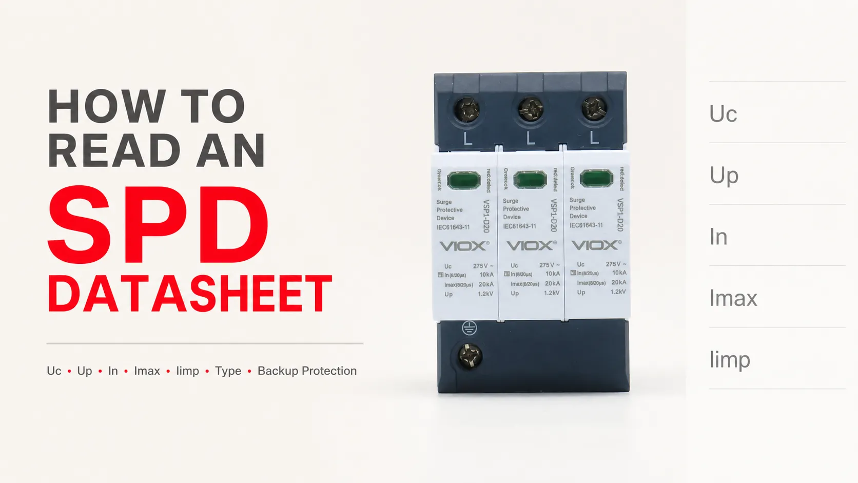
When you open a surge protective device (SPD) datasheet, the first thing you see is usually a wall of numbers: Uc 275 V, Up ≤ 1.5 kV, In 20 kA, Imax 40 kA, Iimp 12.5 kA, Type 1, Type 2, backup fuse, and sometimes SCCR, Isccr, or VPR. The trap is assuming one number tells the whole story. It does not.
When reading an SPD datasheet, start with system voltage and protection type, then verify Uc/MCOV, Up, In, Imax, Iimp, Type 1/2/3, AC or DC rating, and backup fuse or breaker requirement. Do not choose a surge protective device only by the largest kA number. A correct SPD must match the real system voltage, earthing system, installation location, surge exposure, standards framework, and upstream protection.
For a general device overview first, see What Is a Surge Protective Device (SPD)?. This guide focuses specifically on reading datasheets and nameplates like a buyer, panel builder, or electrical engineer.
SPD Datasheet Reading Order
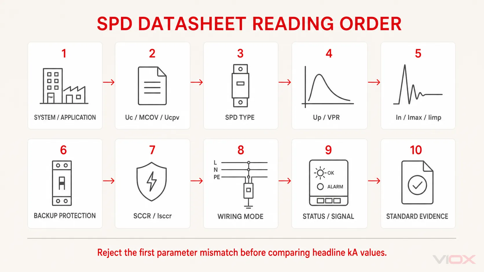
The safest way to read an SPD datasheet is not from top to bottom. Read it in the order that disqualifies wrong products fastest.
| Step | What to check | Why it matters |
|---|---|---|
| 1 | System type: AC, DC, PV, signal, TN-S, TN-C-S, TT, IT | SPD wiring and voltage mode depend on the system |
| 2 | Uc / MCOV / Ucpv | Must be high enough for continuous operating voltage |
| 3 | SPD Type: Type 1, Type 2, Type 3, Type 1+2 | Must match installation point and surge exposure |
| 4 | Up / VPR | Characterizes voltage-limiting performance under the applicable test framework |
| 5 | In, Imax, Iimp | Shows surge discharge duty under different test waveforms |
| 6 | Backup protection | Fuse or breaker coordination may be required |
| 7 | SCCR or applicable short-circuit withstand/current declaration, such as Isccr | Must be compatible with the prospective short-circuit current and upstream protection |
| 8 | Wiring mode and pole configuration | L-N, L-PE, N-PE, 3+1, 4+0, DC+/DC-, DC-to-PE |
| 9 | Status indication and remote signaling | Needed for maintenance and monitoring |
| 10 | Standard and certification basis | IEC, UL, GB, EN, or project-specific requirements |
This sequence prevents a common mistake: selecting the SPD with the highest Imax first, then discovering later that the continuous voltage, backup fuse, or installation Type is wrong.
SPD Nameplate / Datasheet Example
A typical low-voltage power SPD label may include markings like:
Type 2, Uc 275 VAC, Up ≤ 1.5 kV, In 20 kA, Imax 40 kA, 8/20 μs, IEC 61643-11, max backup fuse 125 A gG, remote contact optionalHere is how to read it:
| Marking | What it tells you | What to verify |
|---|---|---|
| Type 2 | SPD class for distribution-level surge protection | Is Type 2 suitable for the installation point? |
| Uc 275 VAC | Maximum continuous operating voltage | Does it match the system voltage and earthing arrangement? |
| Up ≤ 1.5 kV | Voltage protection level under standard test conditions | Is downstream equipment adequately protected? |
| In 20 kA | Nominal discharge current, usually 8/20 μs for Type 2 | Is repeated surge duty adequate for the site? |
| Imax 40 kA | Maximum discharge current under 8/20 μs test waveform | Do not treat this as normal repeated capacity |
| IEC 61643-11 | Product-standard marking for low-voltage AC power SPDs | Confirm the edition, certificate scope, model, and supporting test documentation |
| Max backup fuse 125 A gG | Manufacturer-declared maximum permissible overcurrent protection for the stated SPD configuration | Compare the system-side device with the manufacturer instruction and determine whether dedicated branch protection is required |
| Remote contact | Allows status signal to BMS/PLC/alarm circuit | Check contact rating and fail indication logic |
The values above are an example format, not a universal recommendation. Always follow the exact datasheet and local electrical code.
Which IEC standard edition should you verify?
For current low-voltage AC power SPDs, IEC 61643-01:2024 contains the common requirements for SPDs, while IEC 61643-11:2025 contains the AC-specific requirements and is applied together with IEC 61643-01. A label that says only “IEC 61643-11” is not enough to establish the edition, certificate scope, or whether the shipped model matches the tested construction.
Other applications use different parts of the series. For example, PV SPDs are covered by IEC 61643-31, while telecommunications and signaling-network SPDs are covered by IEC 61643-21:2025, which is also used with IEC 61643-01:2024. Verify the product category before comparing ratings across standards.
Uc / MCOV: Maximum Continuous Operating Voltage
Uc is the IEC term for maximum continuous operating voltage. In North American terminology, MCOV means maximum continuous operating voltage. For PV DC SPDs, the datasheet may use Ucpv.
This is usually the first rating to check because an SPD connected to a voltage higher than its continuous rating can overheat, age rapidly, or fail prematurely.
Common buyer mistake
Choosing Uc too close to nominal voltage.
For example, a 230/400 V AC system is not selected by reading only "230 V" from the catalog. The correct Uc depends on line-to-neutral or line-to-earth connection mode, earthing system, voltage tolerance, and the manufacturer’s intended wiring scheme.
For a deeper guide, see What Do Uc and Up Mean on SPD? and MCOV SPD Maximum Continuous Operating Voltage Guide.
Up: Voltage Protection Level
Up is the declared voltage protection level established under the applicable standardized tests. It characterizes the SPD’s voltage-limiting performance, but it should not be treated as the exact voltage that every downstream device will experience in an installed system.
Lower Up is generally desirable because it means less surge voltage reaches downstream equipment. But lower Up is only useful when Uc, Type, coordination, lead length, and system compatibility are correct. An SPD with a very low Up but wrong Uc, wrong Type, poor coordination, or unsuitable backup protection is still the wrong product.
What procurement should check
- Up value for the relevant mode of protection
- coordination with upstream and downstream SPDs
- distance to protected equipment
- lead length and installation quality
- equipment impulse withstand level
Installation matters. Long SPD leads increase effective let-through voltage even when the datasheet Up looks good. If placement is the question, see Where to Install SPDs: Electrical Panel Guide.
Why lead length can make real Up worse than datasheet Up
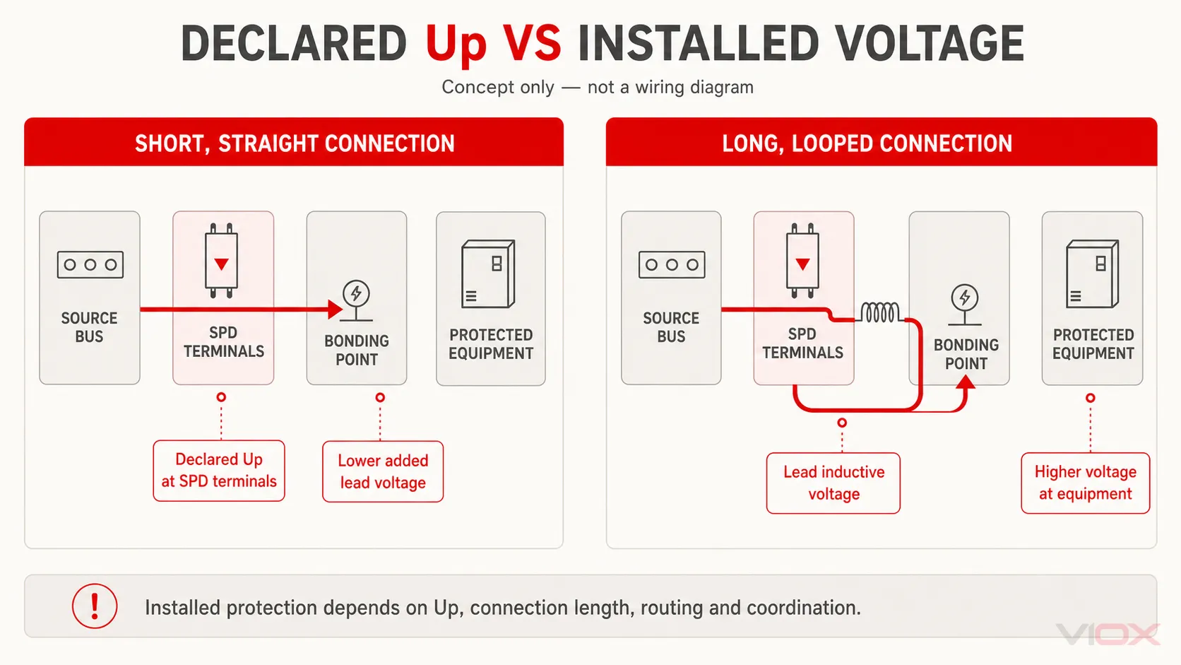
The declared Up is established from standardized tests at the SPD terminals. In a real panel, the connecting conductors add inductive voltage drop during a fast surge current. The voltage appearing at the protected equipment can therefore be higher than the printed Up value.
That is why SPD installation guides emphasize short, straight conductors and a low-impedance path to the protective earth or bonding point. Two SPDs with comparable declared Up values can provide different installed protection when their connection lengths and routing differ.
The engineering rule is simple: read Up on the datasheet, but judge protection by the installed circuit path.
Current Ratings Decoded: In, Imax, and Iimp
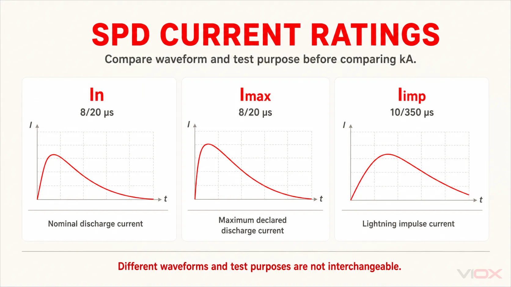
SPD current ratings are not all the same kind of kA number. They use different waveforms and answer different procurement questions.
| Rating | Common waveform | What it tests | Common context | Procurement mistake |
|---|---|---|---|---|
| In | 8/20 μs | Nominal discharge current and repeated surge duty | Type 2 SPD evaluation | Ignoring endurance and buying by Imax only |
| Imax | 8/20 μs | Maximum declared discharge current under test conditions | Type 2 SPD headline capacity | Treating it as normal repeated capacity |
| Iimp | 10/350 μs | Lightning impulse current capability | Type 1 or Type 1+2 SPD | Comparing it directly with Imax |
For procurement, In is generally more informative than Imax when comparing nominal discharge-current duty within the same test framework, while Iimp is the key declared parameter when the project requires lightning-current impulse capability. A large Imax can look impressive on a catalog page, but it does not compensate for wrong Uc, high Up, missing backup protection, or the wrong SPD Type.
In vs Imax: Nominal vs Maximum Discharge Current
In is nominal discharge current, commonly associated with repeated surge duty under the 8/20 μs waveform for many Type 2 SPDs.
Imax is maximum discharge current, also typically based on an 8/20 μs waveform for Type 2 SPDs. It represents a higher declared surge level under test conditions, but it should not be treated as the current the SPD can repeatedly handle in normal service.
| Rating | Meaning | Buyer mistake |
|---|---|---|
| In | Nominal discharge current; helps indicate repeated surge duty | Ignoring it and looking only at Imax |
| Imax | Maximum discharge current under declared waveform | Treating it as normal operating capacity |
| 8/20 μs | Surge current waveform commonly used for Type 2 testing | Comparing kA values without checking waveform |
For a detailed comparison, see Imax vs In Ratings for Surge Protection Devices and SPD kA Rating Sizing Guide.
Iimp: Why Type 1 SPDs Use Impulse Current
Iimp means impulse current. It is typically associated with Type 1 SPDs and the 10/350 μs waveform. At the same peak current, this test impulse represents substantially greater charge and specific-energy duty than an 8/20 μs impulse, so the two kA values are not interchangeable.
This is where many procurement mistakes happen. A 25 kA value is not automatically better or worse than a 40 kA value unless the waveform and SPD Type are the same.
| Parameter | Common waveform | Common SPD context | What it indicates |
|---|---|---|---|
| In | 8/20 μs | Type 2 | Nominal surge discharge duty |
| Imax | 8/20 μs | Type 2 | Maximum declared discharge current |
| Iimp | 10/350 μs | Type 1 | Lightning impulse current capability |
If the building has external lightning protection, overhead service exposure, or project requirements for lightning-current discharge, Type 1 or Type 1+2 SPD selection may be required. Do not substitute a Type 2 Imax value for a Type 1 Iimp requirement.
Type 1 vs Type 2 vs Type 3 SPD
SPD Type describes where and how the device is intended to be used. IEC Type 1/2/3 and UL Type 1/2/3 are related concepts but not identical systems, so do not compare them without checking the applicable standard.
| IEC SPD Type | Typical IEC application context | Key rating focus |
|---|---|---|
| Type 1 | Origin of the installation or an LPZ boundary where partial lightning current may be expected | Iimp, follow-current behavior where applicable, upstream coordination |
| Type 2 | Main distribution board or sub-distribution board | In, Imax, Up, Uc |
| Type 3 | Near sensitive equipment and coordinated with upstream protection | Uoc or applicable combination-wave data, voltage protection level, coordination |
| Type 1+2 | Combined lightning-current and surge protection | Iimp plus Type 2 performance parameters |
These are typical IEC application contexts, not universal location labels. UL Type designations follow the UL 1449 framework and should be interpreted from the applicable UL product documentation rather than mapped directly to the IEC table.
For a full comparison, see Surge Protective Device Type 1 vs Type 2 vs Type 3.
AC SPD vs DC / PV SPD Ratings
AC and DC SPDs are not interchangeable unless the datasheet explicitly supports the application.
For AC power systems, read:
- Uc / MCOV
- system voltage
- earthing system
- Type 1/2/3
- pole configuration
- backup fuse or breaker
- SCCR or the applicable short-circuit withstand/current declaration, such as Isccr
For PV DC or BESS DC applications, also read:
- Ucpv or rated DC operating voltage
- maximum PV string open-circuit voltage
- polarity and wiring mode
- DC+/DC-, DC-to-PE protection modes
- IEC 61643-31 or relevant DC/PV SPD standard basis
- backup protection and DC short-circuit behavior
For DC-specific applications, see DC Surge Protection Devices: PV, EV Charging, BESS, and Industrial DC SPD Selection Guide and BESS Surge Protection Guide.
Backup Fuse or Backup Breaker Requirement
The backup fuse or backup breaker line is a manufacturer installation limit, not a decorative specification. It identifies the permitted overcurrent-protection arrangement for the stated SPD configuration and must be interpreted together with the system-side protective device, prospective short-circuit current, conductor arrangement, and manufacturer instructions.
Depending on the SPD design and installation, backup protection may be required to:
- disconnect the SPD safely after end-of-life failure
- coordinate with available short-circuit current
- prevent upstream protection from exceeding tested conditions
- meet manufacturer installation instructions
- satisfy local code or panel standard requirements
What to check
| Datasheet line | Why it matters |
|---|---|
| Max backup fuse | Compare the system-side protection with the declared maximum; a dedicated SPD branch fuse may be required when the upstream device exceeds it |
| Backup breaker option | Confirm breaker curve, rating, and breaking capacity if allowed |
| SCCR / Isccr / applicable short-circuit declaration | Verify the exact standard, voltage, protection combination, and prospective fault-current condition |
| Integrated disconnector | Does not always remove the need for upstream protection |
| Fuse type | gG, gL, class, or manufacturer-specific requirement must be followed |
If the datasheet says backup protection is required, do not omit it because the SPD already has an indicator or thermal disconnector.
How to interpret “max backup fuse 125 A gG”
Do not automatically read this marking as “the entire installation may not have an upstream fuse larger than 125 A.” For a branch-connected SPD, use the manufacturer’s coordination instructions:
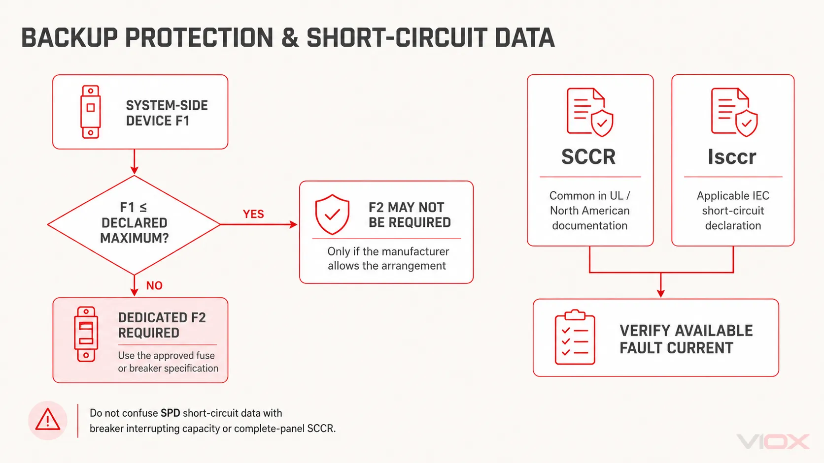
- If the system-side protective device F1 is at or below the permitted value, a separate SPD branch fuse F2 may not be required, provided the manufacturer allows that arrangement.
- If F1 exceeds the declared maximum, a dedicated branch fuse or other approved overcurrent protective device is normally required.
- If a circuit breaker is permitted instead of a gG fuse, verify its rating, trip characteristic, interrupting capacity, and the manufacturer’s stated equivalence. Do not assume equal ampere ratings are interchangeable.
- Check the impulse withstand of the selected backup device so it does not disconnect the SPD during a surge within the intended duty.
Short-circuit terminology also depends on the standards framework. SCCR is common in North American and UL documentation. IEC datasheets may instead declare a short-circuit withstand/current value such as Isccr. Neither value should be confused with the interrupting rating of the upstream breaker or with the SCCR of the complete panel.
For installation mistakes, see SPD Installation Mistakes Fix Guide and SPD Installation Requirements: Code and Safety Standards.
Remote Signaling, Failure Indicator, and Replaceable Module
SPD status indication matters because an SPD can reach end of life after repeated surge exposure. If no one checks the indicator, the panel may appear protected while the SPD module is no longer functional.
Common status features include:
- visual green/red window
- plug-in replaceable module
- remote signaling contact
- alarm output for BMS, PLC, SCADA, or panel lamp
- cartridge keying to prevent wrong replacement
When reading the datasheet, confirm whether the remote contact is normally open, normally closed, changeover, or fail-safe in the required alarm logic. Also check the contact rating before wiring it into an alarm circuit.
What SPD Ratings Do Not Tell You
Two SPDs can show similar headline ratings: Type 2, Uc 275 VAC, Up ≤ 1.5 kV, In 20 kA, Imax 40 kA. That does not automatically mean they will age, disconnect, indicate failure, or perform consistently in the same way.
Datasheets tell you the declared test ratings. They do not fully show the manufacturing discipline behind those ratings.
MOV quality and consistency
Many low-voltage power SPDs use metal oxide varistors (MOVs) as the main voltage-limiting component. The MOV characteristics influence clamping behavior, leakage current, aging, thermal stress, and current sharing between protection paths.
For procurement, ask:
- Are the MOV ratings suitable for the declared Uc and surge duty?
- Are MOVs matched consistently across poles or modules?
- Is there batch traceability for critical surge components?
- Does the manufacturer control incoming component inspection?
This does not mean every buyer needs to audit MOV production. It means a serious supplier should be able to explain the component quality controls behind the SPD rating.
Thermal disconnector design
An SPD is expected to fail safely at end of life. For MOV-based SPDs, the thermal disconnector is a critical safety feature. It disconnects the MOV from the circuit when overheating or degradation creates an unsafe condition.
When comparing products, check:
- whether the SPD has an internal disconnector
- how failure indication is linked to the disconnection mechanism
- whether the module has visible status indication
- whether external backup protection is still required
- whether the datasheet explains end-of-life behavior clearly
Do not assume that a green/red window alone proves the disconnection design is robust. The indicator is only useful if it correctly reflects the internal protection state.
Housing, arc control, and flame behavior
SPD housing materials and internal layout matter because surge components can experience thermal and electrical stress. The datasheet may list flame rating, insulation data, or standard compliance, but the buyer should still check whether the product is suitable for the panel environment and expected fault level.
Important review points include:
- housing flame-retardant rating where stated
- spacing and insulation design
- internal separation of live parts
- module locking and replacement design
- terminal strength and conductor compatibility
Avoid making decisions only from the front label. The quality of the internal disconnector and enclosure design is part of real SPD safety.
Certification and production consistency
A certificate or standard reference is important, but it must match the actual model being purchased. For OEMs, distributors, and panel builders, the practical question is not only "was a sample tested?" but also "does production remain consistent with the tested design?"
Ask for:
- exact model number match between datasheet, certificate, and product label
- applicable standard and test report scope
- production batch traceability
- component change control
- installation instructions matching the shipped product
- clear backup fuse or breaker instructions
This section is where serious procurement teams separate a real specification from a catalog claim.
Common Procurement Mistakes
1. Buying by Imax only
A high Imax number looks attractive, but it does not prove the SPD is suitable. Uc, Up, Type, waveform, backup protection, and installation point all matter.
2. Comparing Type 1 Iimp with Type 2 Imax
These values are based on different waveforms and test purposes. Do not compare them as if they were the same kind of kA rating.
3. Ignoring Uc / MCOV
An SPD with too low a continuous operating voltage may fail prematurely. An SPD with too high a voltage rating may provide less effective voltage limitation. Select based on the real system.
4. Treating lower Up as always better
Lower Up is useful only when the SPD is correctly coordinated and installed. Lead length, grounding path, upstream SPD coordination, and system voltage still matter.
5. Using AC SPD on PV DC circuits
DC/PV systems require DC-rated SPDs with suitable Ucpv and wiring mode. Do not use AC markings as a substitute for PV/DC ratings.
6. Missing backup protection
If the SPD datasheet specifies a maximum backup fuse or breaker, it must be considered in panel design.
7. Confusing product standards
IEC 61643-01:2024, IEC 61643-11:2025, IEC 61643-31, IEC 61643-21:2025, UL 1449, and GB/T 18802 do not all serve the same product category or certification framework. For an AC IEC product, read IEC 61643-11:2025 together with IEC 61643-01:2024; for other applications, verify the applicable part and edition.
For standard comparison, see Surge Protection Standards: IEC 61643 vs UL 1449 vs GB 18802.
SPD Specification Checklist
Use this checklist before approving an SPD for purchase or panel assembly.
| Check item | Pass / fail question |
|---|---|
| System type | Is it AC, PV DC, BESS DC, EV charging, signal, or data line? |
| Voltage | Does Uc / MCOV / Ucpv match the actual system voltage and tolerance? |
| Installation point | Is the SPD Type suitable for service entrance, distribution board, or equipment-side use? |
| Earthing system | Does the SPD wiring fit TN-S, TN-C-S, TT, IT, or project-specific grounding? |
| Protection level | Is Up suitable for downstream equipment and coordination? |
| Surge duty | Are In, Imax, or Iimp appropriate for the exposure level? |
| Waveform | Are you comparing 8/20 μs with 8/20 μs and 10/350 μs with 10/350 μs? |
| Backup protection | Is the fuse/breaker requirement included in the panel design? |
| Short-circuit data | Is the applicable SCCR, Isccr, or other declared short-circuit value compatible with the available fault current and upstream protection? |
| Module status | Is visual indication or remote signaling needed? |
| Standard | Does the standard match the market and application? |
| Documentation | Are datasheet, wiring diagram, certificate, and model number aligned? |
FAQ
What is the most important SPD rating?
There is no single most important rating. Uc/MCOV comes first because the SPD must survive normal system voltage. After that, check Type, Up, In, Imax, Iimp, backup protection, and standard basis.
Is Imax more important than In?
No. Imax shows maximum declared discharge current under test conditions, usually for Type 2 SPDs with an 8/20 μs waveform. In is more useful for understanding nominal repeated surge duty. Both must be read together.
What is the difference between Uc and Up?
Uc is the maximum continuous operating voltage for the stated mode and conditions. Up is the declared voltage protection level established under the applicable standardized tests. Uc is about compatibility with continuous system voltage; Up characterizes surge-voltage limitation, while the voltage at the protected equipment also depends on the installed connection path and coordination.
What does Iimp mean on an SPD?
Iimp means impulse current. It is usually associated with Type 1 SPDs and the 10/350 μs waveform used for lightning-current impulse testing.
Can I compare 40 kA Imax with 25 kA Iimp?
Not directly. Imax and Iimp use different waveforms and test purposes. At the same peak current, the 10/350 μs test impulse represents substantially greater charge and specific-energy duty than the 8/20 μs impulse.
Does every SPD need a backup fuse?
Not always in the same way, but the datasheet must be followed. Some SPDs require external backup protection under certain upstream fuse or fault-current conditions. Others may include internal disconnecting devices but still have installation limits.
What does remote signaling mean on an SPD?
Remote signaling means the SPD has an auxiliary contact that reports status to a panel lamp, BMS, PLC, SCADA, or alarm circuit. Check the contact type and rating before wiring.
Can AC SPDs be used in DC or PV systems?
Only if the datasheet explicitly rates the SPD for that DC or PV application. PV/DC systems require correct Ucpv, wiring mode, polarity where applicable, and DC/PV standard basis.
Summary
Reading an SPD datasheet correctly is mostly about order and context. Start with system voltage and application type, then confirm Uc/MCOV, Up, Type, In, Imax, Iimp, backup protection, wiring mode, status indication, and standard basis.
The strongest procurement habit is simple: never approve an SPD by a single kA number. A suitable SPD is the one whose complete rating set matches the real electrical system, installation point, surge exposure, and panel protection design.
For product review, see the VIOX SPD product page, or use the related guides above to compare individual parameters in more detail.
Sources Used
- IEC 61643-01:2024: General requirements and test methods for SPDs
- IEC 61643-11:2025: SPDs connected to AC low-voltage power systems
- IEC 61643-21:2025: SPDs for telecommunications and signaling networks
- Phoenix Contact: The right backup fuse for surge protective devices
- VIOX: What Is a Surge Protective Device?
- VIOX: Uc and Up Mean on SPD
- VIOX: Imax vs In Ratings for SPDs
- VIOX: Surge Protection Standards IEC 61643 vs UL 1449 vs GB 18802