On this page
An AC fuse and a DC fuse perform the same basic job—opening a circuit after excessive current heats and melts the fuse element—but they are not interchangeable merely because their ampere ratings match. Use a fuse only when its marking or manufacturer documentation gives the required alternating-current (AC) or direct-current (DC) voltage rating and breaking capacity for the actual circuit.
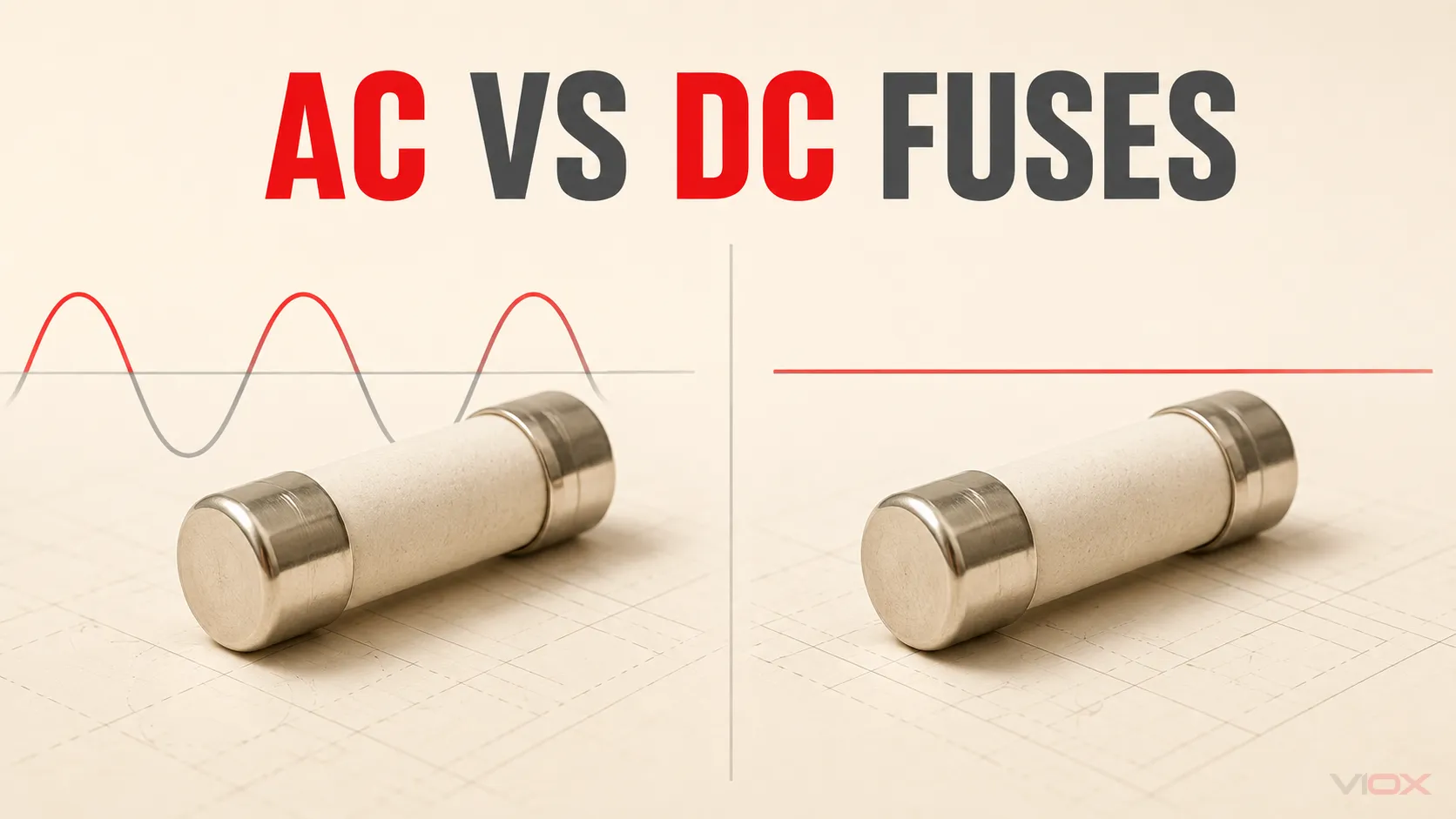
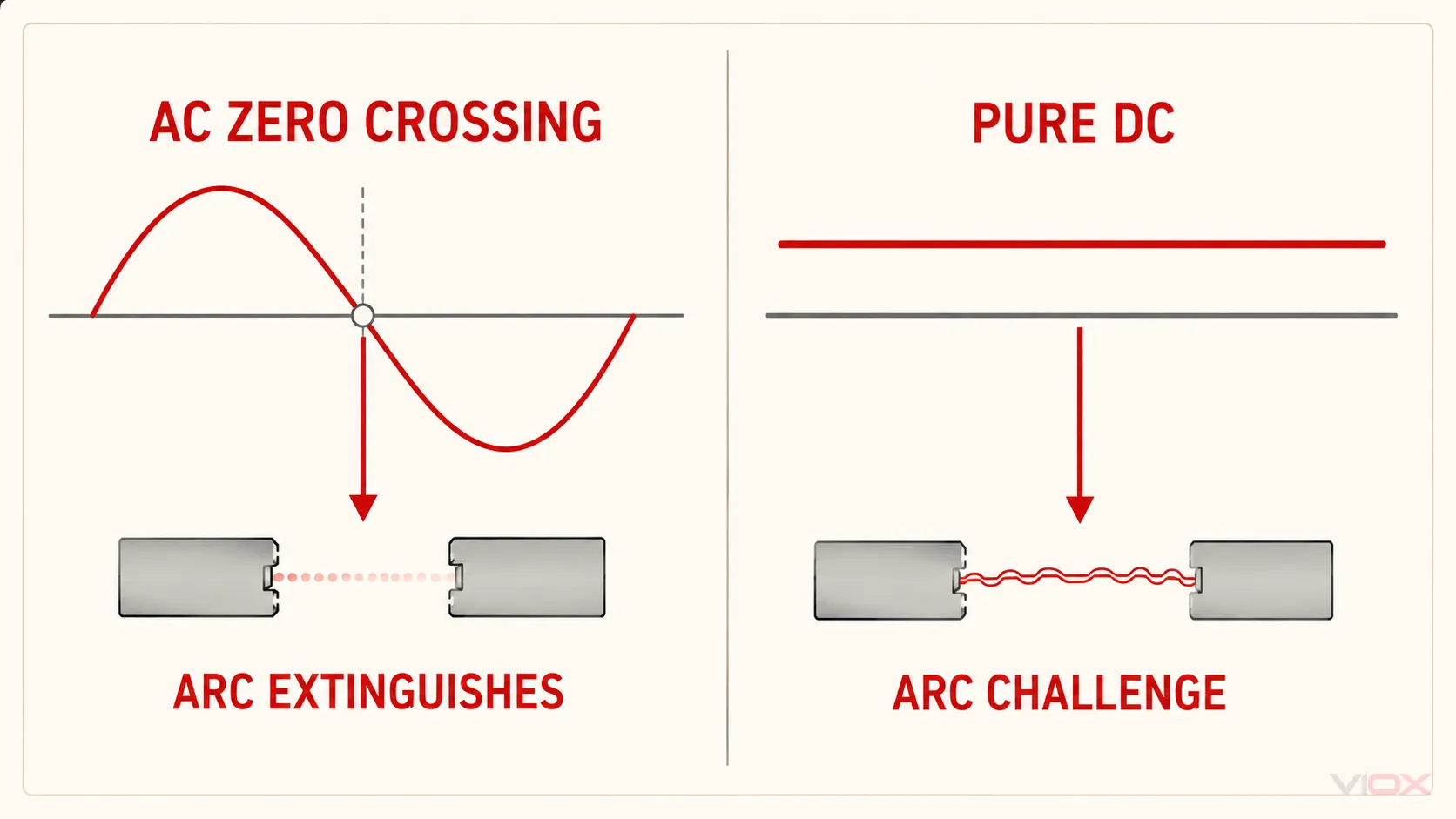
The main engineering difference appears after the element melts. AC current passes through a natural current zero every half-cycle, which assists arc extinction. Pure DC has no periodic natural current zero, so the fuse must interrupt a potentially persistent arc while accounting for circuit voltage, available fault current, and—in many applications—the DC circuit time constant. A fuse can be AC-only, DC-only, or dual-rated. The label and datasheet, not the product’s appearance, decide which case applies.
AC Fuse vs DC Fuse: The Decision Table
| Decision point | AC application | DC application | What must be verified |
|---|---|---|---|
| Current waveform | Alternating current reverses and passes through zero periodically | Pure DC maintains one polarity and has no periodic natural current zero | The current type at the fuse location—not merely the equipment’s input or output label |
| Arc interruption | Natural current zeros assist extinction after the element melts | The fuse construction must force the arc to cool, lengthen, divide, and extinguish without natural zero crossings | AC or DC voltage marking and manufacturer application data |
| Voltage rating | Use the stated AC voltage rating at or above the circuit’s applicable voltage | Use the stated DC voltage rating at or above the maximum applicable DC voltage | Separate VAC and VDC values when both are listed |
| Breaking capacity | Must equal or exceed the prospective fault current under the stated AC conditions | Must equal or exceed the prospective fault current under the stated DC conditions | AC and DC breaking-capacity entries may differ |
| Circuit dynamics | Frequency, power factor, source impedance, and fault duty may matter | Source energy and inductance-to-resistance ratio can change current rise and interruption duty | Manufacturer limits and test basis for the intended circuit |
| Time-current behavior | Use the curve supplied for the exact fuse family and AC duty | Use the applicable DC curve or manufacturer confirmation where AC and DC behavior differ | Curve type, test conditions, preloading, ambient, and tolerance |
| Physical construction | May use ceramic bodies, fillers, multiple elements, arc plates, or other features | May use similar features, sometimes arranged differently for the DC duty | Do not classify the fuse by size, body material, or filler alone |
| Substitution | Accept only when the candidate has suitable AC data | Accept only when the candidate has suitable DC data | Exact catalog number, not a visually similar fuse |
The practical rule is short: match the fuse to the current type, voltage, fault current, operating requirement, and published application conditions. A current rating by itself answers none of the interruption questions.
Why DC Arc Interruption Is More Demanding
A fuse does not finish operating at the instant its element melts. Melting creates a gap, but current may continue through an electrical arc inside that gap until the fuse extinguishes the arc and withstands the recovery voltage.
In an AC circuit, instantaneous current naturally reaches zero every half-cycle. This does not make AC interruption automatic or make every AC fuse simple: system voltage, fault current, power factor, fuse construction, and test standard still matter. It does, however, provide repeated opportunities for the arc to extinguish.
In a pure DC circuit, current does not periodically pass through zero. The fuse must create the conditions that drive the arc current to zero. Depending on the fuse design, those conditions may involve a longer arc path, multiple element restrictions, arc division, cooling surfaces, or granular filler. These are design possibilities, not a visual checklist. Industrial AC fuses can also be filled and current-limiting, while some low-voltage DC fuses are compact. “Sand-filled,” “ceramic,” or “longer” does not by itself prove a DC rating.
The DC time constant changes the duty
DC fault current does not always rise instantly. Circuit inductance resists the change in current. For a simple resistive-inductive circuit, the time constant is:
τ = L / Rwhere L is inductance and R is resistance. A larger L/R value means a slower current rise and more stored magnetic energy for the fuse to manage during interruption. Eaton’s Bussmann high-speed fuse guidance explains that DC voltage capability and fuse behavior can depend on this time constant; it also shows why an AC-to-DC rating cannot be derived from one universal percentage.
Use the fault-condition time constant when the manufacturer requires it. The normal operating time constant may not represent the circuit after a short circuit, and battery, traction, converter, and large DC-drive systems can present materially different source behavior.
The Four-Proof Test for AC/DC Interchangeability
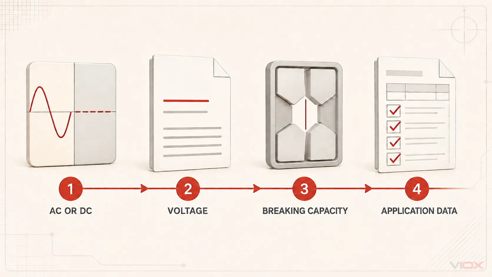
Treat interchangeability as an evidence check. A candidate fuse passes only when all four proofs are available for the exact catalog number.
Proof 1: Correct current type and voltage rating
Read the voltage marking and datasheet literally:
250 VACestablishes an AC rating only unless separate DC data is published.125 VDCestablishes a DC rating only unless separate AC data is published.250 VAC / 125 VDCis a dual rating with two distinct limits; it does not mean 250 V is permitted for both.- A plain voltage value without a clear AC/DC basis requires the manufacturer’s documentation and the governing product-marking rules to be checked.
The fuse’s voltage rating must be at least the maximum applicable circuit voltage for the stated current type. Do not convert RMS AC voltage to DC voltage using a homemade equivalence rule. Voltage waveform is only one part of interruption performance.
Proof 2: Adequate breaking capacity at that rating
Breaking capacity—also called interrupting rating—is the prospective current that the manufacturer states the fuse can safely interrupt under defined conditions. It is different from the fuse’s normal current rating.
A 20 A fuse, for example, may be installed in a circuit capable of delivering fault current many times greater than 20 A. The selected fuse therefore needs both:
- a current rating and time-current characteristic suitable for the load and protected conductors or equipment; and
- a breaking capacity that is not less than the prospective fault current at its installation point, under the applicable AC or DC test basis.
Do not assume the AC breaking capacity also applies to DC. If the datasheet publishes separate values, use the value for the actual circuit. If it publishes no DC value, obtain written manufacturer application guidance or select a fuse with documented DC capability.
Proof 3: Suitable operating characteristic
Matching voltage and breaking capacity does not complete the selection. The fuse must carry normal load and intended transient current while operating within the time required to protect the circuit.
Verify the exact fuse family’s:
- time-current curve and whether it shows minimum melting, average melting, or total clearing;
- pre-arcing and total-clearing I²t where equipment energy withstand matters;
- peak let-through data in the current-limiting region;
- utilization category or fuse class;
- ambient-temperature, preloading, cyclic-duty, and fuseholder conditions.
AC and DC time-current behavior may converge in some longer-duration regions, but that observation does not establish DC interruption capability. Use the curve and application notes supplied for the intended duty.
Proof 4: Application and installation conditions
Confirm the conditions that can invalidate an otherwise promising rating:
- DC L/R time constant and source configuration;
- battery or capacitor energy;
- converter or regenerative-drive topology;
- minimum and maximum prospective fault current;
- fuseholder voltage, current, temperature, and breaking-duty compatibility;
- required standard, approval, and market documentation;
- enclosure temperature, ventilation, altitude, and cyclic loading where the manufacturer treats them as selection variables.
The fuseholder is part of the installed protection system. A correctly rated fuse-link in an unsuitable holder is not a valid assembly. The fuse-link versus fuse terminology guide explains the distinction between the replaceable link and the complete fuse device.
Can an AC Fuse Be Used in a DC Circuit?
Not on the basis of its AC marking or equal ampere rating. An AC-rated fuse may be used in a DC application only when the manufacturer provides a DC rating or application data covering the intended system conditions.
Consider a cartridge fuse marked 250 VAC with no visible DC value. Even if the target circuit is only 48 VDC and the ampere rating appears correct, the marking alone does not prove that the fuse can interrupt the available DC fault current. The next step is not to apply a fixed derating percentage; it is to find the exact catalog datasheet or obtain manufacturer confirmation.
Some manufacturer engineering guides describe limited ways to evaluate particular AC fuse families in defined DC circuits. Those procedures can depend on DC voltage, minimum short-circuit current, time constant, and circuit topology. They are product-family engineering methods, not general permission to convert any AC fuse to DC service.
Can a DC Fuse Be Used in an AC Circuit?
Do not assume that a DC marking automatically supplies an AC rating. The fuse may be physically capable of interrupting a particular AC duty, but procurement and design approval require published evidence for that use.
If the fuse carries both AC and DC ratings, evaluate the AC circuit against the AC values. If it carries only a DC rating, check the manufacturer documentation rather than treating DC service as a universal “more demanding” certification that automatically covers AC. Test methods, voltage definitions, breaking capacities, utilization categories, and approvals are not interchangeable labels.
How to Read AC-Only, DC-Only, and Dual Ratings
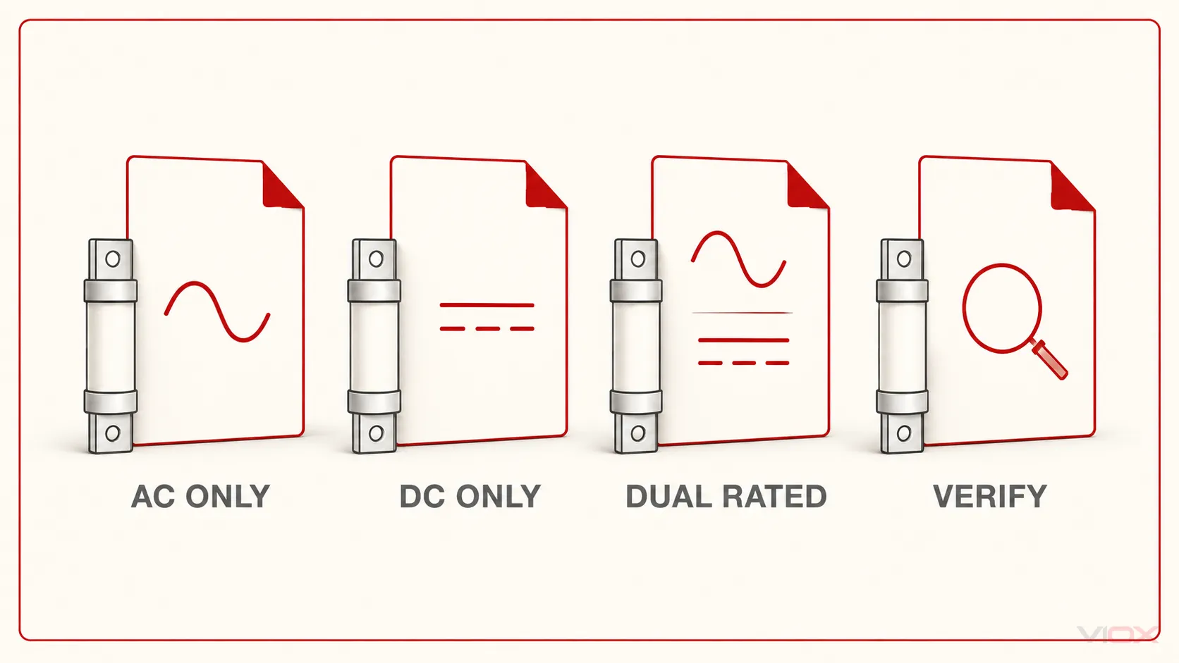
| Documentation found | Decision | Required next action |
|---|---|---|
| AC voltage and AC breaking capacity only | AC-only for the evidence available | Use within the AC ratings or request separate DC application data |
| DC voltage and DC breaking capacity only | DC-only for the evidence available | Use within the DC ratings or request separate AC application data |
| Separate AC and DC voltage and breaking-capacity values | Dual-rated candidate | Check each circuit against its own values and operating conditions |
| One voltage marking but unclear current type | Unverified | Resolve the marking through the exact datasheet or manufacturer |
| Correct voltage but no adequate breaking-capacity evidence | Reject or keep provisional | Determine prospective fault current and obtain matching interruption data |
| Correct ratings but wrong physical system or utilization category | Not interchangeable | Select the correct fuse-link and holder system |
A dual-rated fuse is not a universal fuse. Its AC and DC limits can differ, and the same catalog number may have different breaking capacities or application notes for each current type. Record the data separately in the bill of materials or substitution review.
Why Fixed AC-to-DC Conversion Rules Fail
Rules such as “halve the AC voltage rating for DC” may resemble a value published for one product family, but they are unsafe as general selection rules. Eaton notes that, for many high-speed fuses, the DC rating can be lower than the AC rating and can decrease as time constant increases; the same guide also describes special conditions where DC capability may behave differently. That is precisely why the manufacturer’s defined method must replace a universal ratio.
The following shortcuts are not acceptable evidence:
| Shortcut | Why it fails | Correct evidence |
|---|---|---|
| Same ampere rating | Ampere rating does not establish arc-interruption capability | AC/DC voltage and breaking-capacity data |
| DC voltage is lower than the AC marking | A lower number alone does not prove DC interruption | Published DC rating or application method |
| The DC fuse is longer | Dimensions do not reveal tested duty | Catalog number and datasheet |
| Both fuses contain quartz filler | Construction features are not ratings | Marking, test basis, and manufacturer data |
| The holder accepts the fuse | Mechanical fit does not prove electrical compatibility | Complete fuse-link/holder system verification |
| A similar series has a DC rating | Ratings do not transfer between families or variants | Exact part-number documentation |
Three Application Checks
1. Replacing an AC-only fuse in a control circuit
If the original and replacement both show the required AC voltage, current rating, breaking capacity, operating characteristic, and physical-system compatibility, the comparison can proceed on the AC data. A higher DC rating on one candidate does not compensate for a missing AC class, curve, or approval required by the equipment design.
2. Using a dual-rated fuse in an AC and a DC product variant
Treat the two variants as separate applications. For the AC product, record the VAC and AC breaking-capacity entries. For the DC product, record the VDC and DC breaking-capacity entries plus any permitted time constant or circuit restrictions. Do not copy one completed evaluation across both variants.
3. Protecting PV or battery circuits
The AC/DC comparison is only the first gate. Photovoltaic (PV) strings can require gPV fuse-links and application evidence within the scope of IEC 60269-6; battery systems can present high available fault current and significant stored energy. Use the DC fuse breaking-capacity guide for PV systems for the fault-duty question and the 12 V fuse-sizing guide for low-voltage conductor and load inputs. Do not import a universal multiplier from one market or application into another.
For broader utilization categories and IEC fuse-system selection, use the IEC 60269 fuse guide. The comparison page determines AC/DC suitability; it does not replace the complete sizing and coordination process.
AC/DC Fuse Replacement Record
Use this table for design review, maintenance substitution, or an RFQ.
| Field | Required entry |
|---|---|
| Existing and candidate catalog numbers | |
| Fuse-link and holder system | |
| Circuit current type at fuse location | AC / DC / rectified or converter waveform |
| Maximum applicable circuit voltage | |
| Candidate AC voltage rating | Value / not published / not applicable |
| Candidate DC voltage rating | Value / not published / not applicable |
| Prospective fault current | |
| AC breaking capacity | Value and test basis / not applicable |
| DC breaking capacity | Value and test basis / not applicable |
| DC L/R time constant required | Yes / No / unresolved |
| Time-current characteristic | |
| Pre-arcing and total-clearing I²t | |
| Fuse class or utilization category | |
| Ambient, cyclic, altitude, or holder conditions | |
| Required approval or standard evidence | |
| Manufacturer document and revision | |
| Final disposition | Approved / rejected / manufacturer review required |
The VIOX electrical fuse guide provides the broader selection map. When the application requirements are defined, review the available VIOX low-voltage fuse and holder families or send the circuit voltage, AC/DC duty, normal current, transient profile, prospective fault current, fuse class, required operating time, holder format, and DC time constant where applicable to [email protected].