On this page
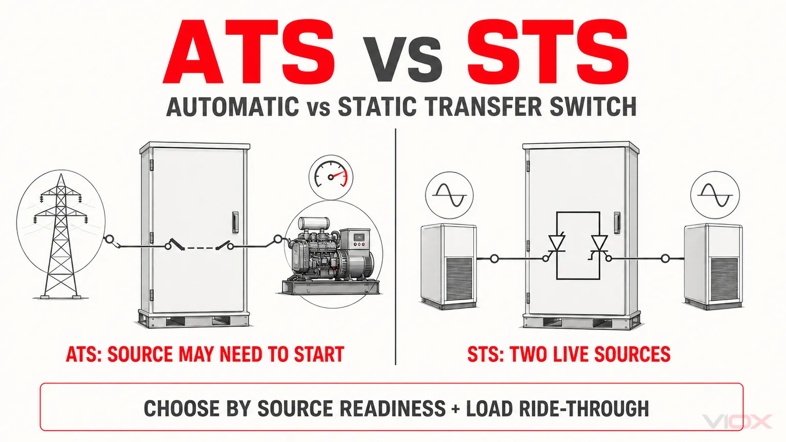
An automatic transfer switch (ATS) is normally the better fit when the alternate source may need to start, particularly in a utility-to-generator system, or when the load can tolerate the declared electromechanical transfer sequence. A static transfer switch (STS) is normally selected when two independent AC sources are already energized and acceptable and a sensitive load requires a much shorter transfer under the manufacturer’s declared source and load conditions.
The devices are therefore not separated by speed alone. They solve different source-availability and continuity problems. In some critical-power systems, the correct answer is both: an ATS manages facility-level utility and generator sources, while a downstream STS transfers a critical load between two live UPS or distribution paths.
ATS vs STS at a Glance
| Decision factor | Automatic transfer switch (ATS) | Static transfer switch (STS) |
|---|---|---|
| Switching path | Electromechanical contacts operated by a transfer mechanism | Solid-state power devices, commonly thyristor or SCR paths |
| Typical source arrangement | Utility-generator, generator-generator, or two available feeders | Two energized, monitored AC sources |
| Alternate source at failure | May be unavailable and require generator starting and stabilization | Normally already energized and within the STS acceptance window |
| Transfer behavior | Open transition is break-before-make; some systems support controlled closed transition | Fast solid-state source transfer controlled to prevent an unintended source-to-source current path |
| Load interruption | Depends on detection, source readiness, intentional delays, mechanism, and transition mode | Often sub-cycle or a few milliseconds, but depends on source relationship, load current, control logic, and product design |
| Main system role | Facility or distribution-level source transfer | Point-of-use or downstream protection of continuity-sensitive loads |
| Continuous conduction | Current flows through closed mechanical contacts | Current flows through semiconductor devices, creating continuous losses and heat that must be managed |
| Fault and protection design | Requires declared short-circuit ratings and system coordination | Requires declared ratings, semiconductor protection, bypass strategy, and system coordination |
| Principal IEC family | IEC 60947-6-1 for transfer switching equipment | IEC 62310-1 and IEC 62310-3 for static transfer systems |
| Typical selection trigger | The backup source must be started or electromechanical isolation is part of the architecture | Both sources are live and the load has limited ride-through capability |
Selection rule: choose by source readiness first, acceptable load interruption second, and equipment ratings third. Do not select either device from an isolated transfer-time number.
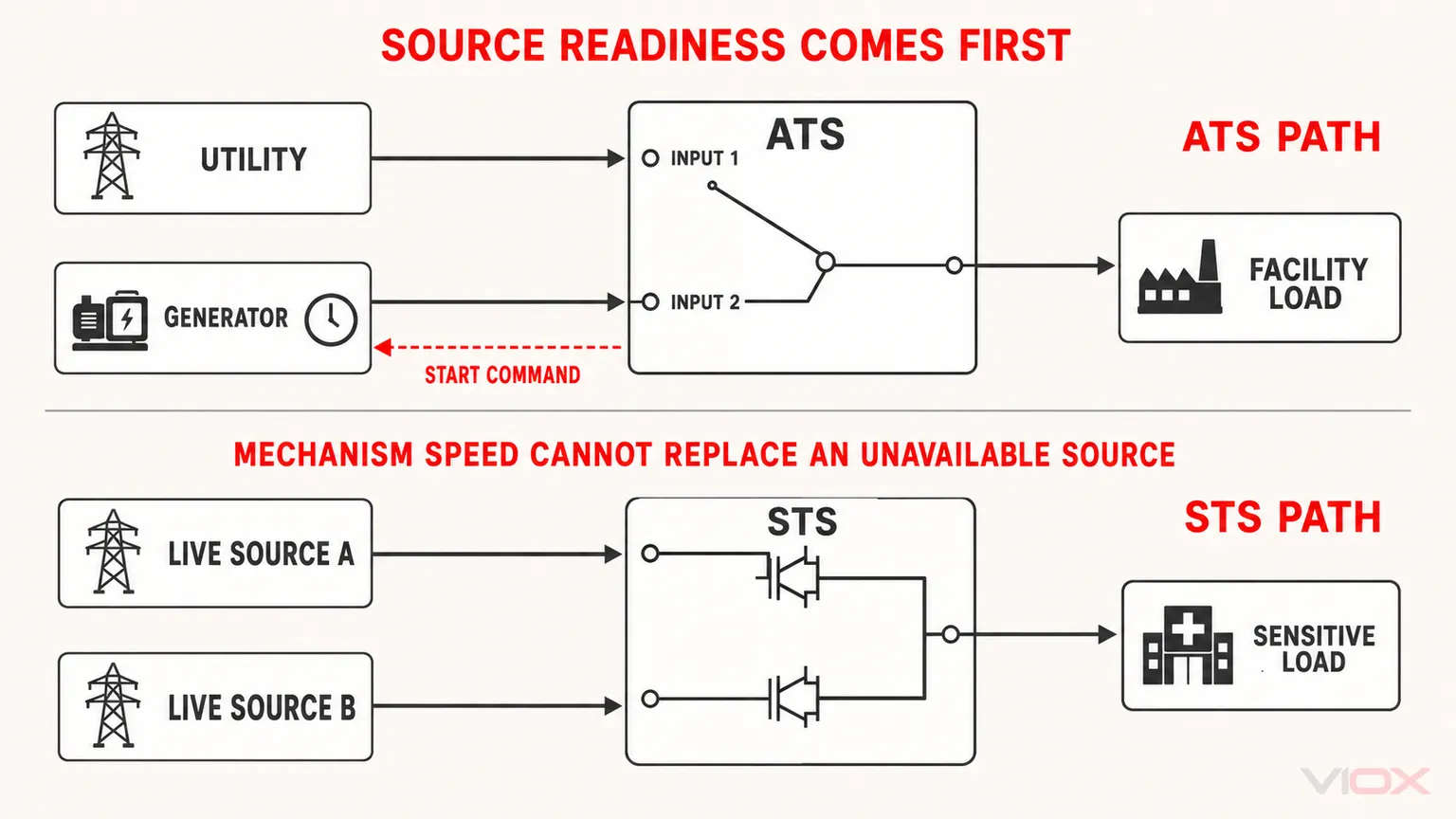
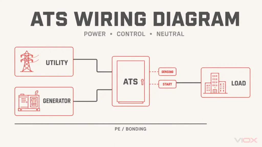
Conceptual architecture only. The dashed line is a generator start command; solid lines are power paths. It is not a product wiring diagram.
Why Transfer-Time Numbers Can Be Misleading
A datasheet may publish a switching or commutation time, but that value is not necessarily the total time for power to be restored to the load. A useful engineering model separates four time components:
| Time component | What it represents | Why it matters |
|---|---|---|
| Failure detection and confirmation | Time required to determine that the preferred source is outside its acceptable limits | Filters and programmed validation can prevent nuisance transfers but add delay |
| Alternate-source readiness | Time required for the alternate source to become usable | Generator starting, acceleration, voltage buildup, and frequency stabilization may dominate the outage |
| Programmed transfer delay | Intentional delay imposed by the controller or operating sequence | May support coordination, avoid transient transfers, or allow a source to stabilize |
| Switching or commutation interval | Time taken by the contacts or semiconductor path to move the load | This is often the number emphasized in product marketing |
Conceptually:
Restoration time depends on detection + source readiness + programmed delay + transfer action.
These events can overlap, so this is a system model rather than a universal arithmetic formula. Its purpose is to show why a fast mechanism cannot compensate for a generator that has not started. The detailed ATS switching-time guide explains why published values must be tied to a specific transfer sequence.
An STS usually avoids the source-starting component because both inputs are expected to be energized. That architectural difference, not the absence of moving parts by itself, is the main reason an STS can restore an eligible load much faster.
How an ATS Transfers Power
An ATS monitors the preferred source and commands an electromechanical transfer mechanism when its control criteria are met. Depending on the product architecture, the switching elements may be contactor-based, switch-disconnector-based, or circuit-breaker-based. It is therefore inaccurate to describe every ATS as a contactor assembly.
In a typical utility-to-generator sequence, the controller detects an unacceptable utility source, sends a generator start signal, waits until the generator voltage and frequency are acceptable, opens the normal-source path, and closes the emergency-source path. The load interruption includes much more than the physical contact movement.
For a fuller operating sequence, see How Does an Automatic Transfer Switch Work?.
For the broader equipment category, source arrangements, and selection boundaries, use the dual-power automatic transfer switch guide.
Open-Transition ATS
Open transition is break-before-make: the switch disconnects one source before connecting the other. The load experiences an interruption, but the arrangement avoids intentionally paralleling the two sources.
This is the common transfer principle where temporary source paralleling is not required or permitted. The actual interruption is product- and sequence-specific; it should not be represented by one universal ATS value.
Closed-Transition ATS
Closed transition is make-before-break. The switch momentarily connects both sources during transfer, but it can do so only when both sources are available and meet the product’s synchronization conditions. The project must also permit the brief source overlap.
Closed transition is especially relevant to planned retransfers or transfers between two acceptable sources. It does not make the initial loss of a utility source to a stopped generator interruption-free. If the alternate source is not energized, no transition mechanism can connect the load to power that does not yet exist.
How an STS Transfers Power
An STS commonly uses opposing or anti-parallel silicon-controlled rectifier (SCR) paths for each AC source. The controller continuously evaluates source conditions and transfers the load by turning off the active path and enabling the alternate path according to its commutation logic.
Because the transfer does not wait for a mechanical contact mechanism, the switching interval can be very short. However, an STS still has operating boundaries:
- Both sources normally need to be energized and within the device’s acceptance criteria.
- The phase relationship between sources affects the voltage step applied to the load.
- Load current and power factor affect SCR commutation behavior.
- The controller may inhibit or delay a transfer when the alternate source is unacceptable.
- Semiconductor conduction produces continuous losses and heat.
- A maintenance bypass and a coordinated protection design may be necessary to service the system without interrupting the load.
For these reasons, “static” should not be translated into an unconditional promise of zero interruption. The specified transfer performance must be read together with the manufacturer’s test conditions, source acceptance window, load assumptions, and bypass architecture.
The Engineering Differences That Change the Specification
1. Is the Alternate Source Already Live?
This is the first and most important question.
If Source B is a standby generator that is normally stopped, an ATS is the natural control and transfer platform. The system must detect the failure, start the generator, verify its output, and then transfer the load.
If Source A and Source B are two live UPS outputs, utility feeders, or independently conditioned distribution paths, an STS may be considered for loads that cannot tolerate the electromechanical interruption.
An STS is not a substitute for generator starting controls. An ATS cannot create static-transfer performance when its alternate source is unavailable.
2. How Much Ride-Through Does the Load Have?
The right comparison is between the load’s ride-through capability and the complete transfer event, not merely the switch mechanism.
A heating load, many motors, and general building circuits may tolerate an open-transition transfer or a generator-start interval, although motor behavior and process consequences still require engineering review. A sensitive server power supply, medical electronics load, control processor, or continuous process may have a much smaller interruption tolerance.
Where the load cannot bridge the source-starting interval, an uninterruptible power supply (UPS), stored energy, redundant power supply, or another continuity measure is required. Choosing a faster ATS does not remove that energy gap.
3. Can the Sources Be Paralleled?
Open-transition ATS equipment avoids intentional source overlap. Closed-transition ATS equipment momentarily parallels sources only under controlled conditions and where the installation permits it.
An STS controller is designed to prevent an unintended current path between its two sources; the exact commutation sequence depends on the product, load current, and source phase relationship. It is not automatically a source-paralleling system. The project must distinguish three separate requirements:
- Avoid source overlap.
- Transfer fast enough for the load.
- Limit the voltage phase step and transient seen by the load.
These are related but not interchangeable requirements.
4. What Happens During a Fault?
Neither ATS nor STS selection is complete without short-circuit and protection coordination.
For an ATS, verify the declared short-circuit rating, the permitted upstream protective device, utilization category, number of poles, neutral switching arrangement, and the ratings of the complete assembly. The distinction between transfer-switch architectures is covered in the VIOX guide to PC Class vs CB Class ATS.
For an STS, verify the prospective fault current, upstream and downstream protection, SCR protection strategy, bypass-path rating, and behavior during downstream faults. A fast source transfer does not replace overcurrent protection or selective coordination.
5. What Continuous Losses and Thermal Conditions Apply?
When an ATS is in a stable position, current passes through closed mechanical contacts. An STS carries load current through semiconductor devices continuously. Its enclosure, cooling arrangement, room heat load, and derating rules therefore require explicit review.
This does not mean an ATS has no thermal limits or that an STS is inefficient. It means the two technologies create and manage conduction losses differently. Compare manufacturer-declared losses and thermal limits at the actual load current rather than applying a generic efficiency percentage.
6. How Will the System Be Isolated and Serviced?
ATS equipment contains moving mechanisms and contacts that must operate reliably after long periods in one position. Exercising, inspection, and maintenance requirements should follow the manufacturer and the criticality of the installation.
An STS has no moving transfer contacts, but it is not maintenance-free. Semiconductor assemblies, control electronics, cooling components, protective devices, connections, and bypass equipment remain part of the service plan.
For critical loads, the important question is not which product is described as lower maintenance. It is whether the architecture provides a safe, rated bypass and a practical method to isolate the transfer equipment without creating an unacceptable outage.
Choose ATS, STS, Both, or Neither
| System condition | Preferred architecture | Engineering reason |
|---|---|---|
| Utility source plus a normally stopped standby generator | ATS | The system must initiate generator starting, validate the source, and execute the transfer sequence |
| Two energized feeders supplying general distribution loads | ATS in many installations; STS only if load continuity requires it | Source availability alone does not justify the cost and thermal complexity of static transfer |
| Two independent UPS outputs supplying sensitive single-cord loads | STS | Both sources are live and the load may require a sub-cycle or few-millisecond transfer under declared conditions |
| Facility utility-generator system with downstream critical IT or control loads | ATS upstream plus UPS/STS downstream | The ATS manages source availability; stored energy and static transfer protect continuity-sensitive loads |
| Load cannot tolerate generator start time and only one live source exists | Neither device alone is sufficient | The design needs stored energy or another continuously available source before transfer technology can solve the interruption |
| Sources cannot be paralleled and the load tolerates interruption | Open-transition ATS | Break-before-make transfer respects the no-parallel requirement without unnecessary static-transfer complexity |
| Planned retransfer must avoid interruption and both sources can be synchronized and briefly paralleled | Closed-transition ATS may fit | Suitability depends on source synchronization, product controls, utility rules, and project authorization |
This table is an architecture screen, not a substitute for equipment ratings. A final specification still requires source, load, fault, environment, and certification data.
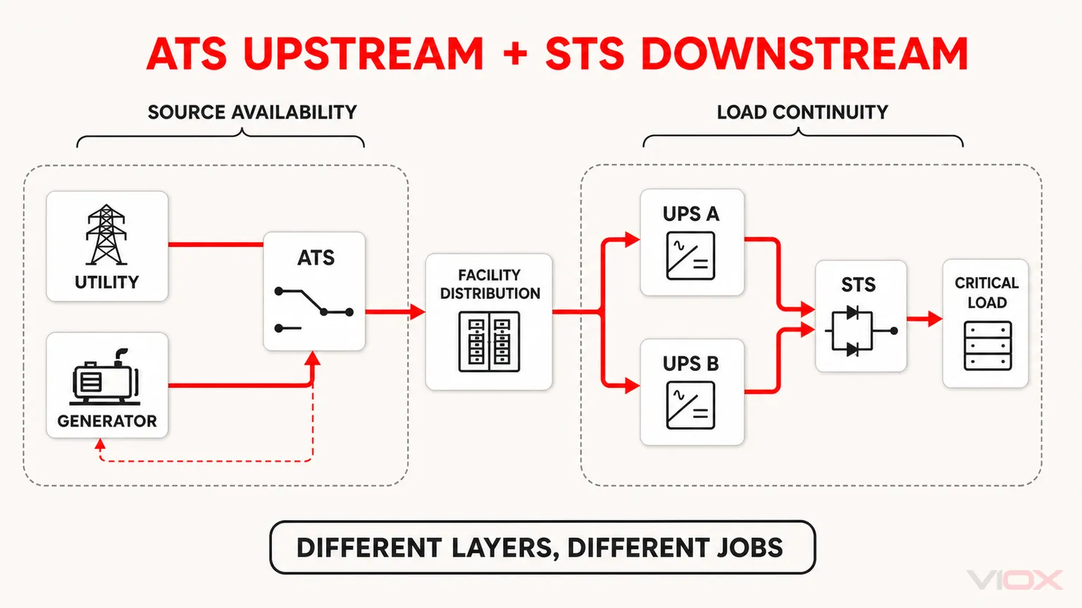
Conceptual system architecture only. The ATS manages source availability; the UPS paths and downstream STS address load continuity. It is not a product wiring diagram.
Why a Closed-Transition ATS Does Not Automatically Replace an STS
Both technologies can reduce or avoid a visible interruption in specific circumstances, but their operating assumptions differ.
A closed-transition ATS needs two acceptable, synchronized sources and permission to overlap them briefly. It is commonly used to improve planned transfer or retransfer behavior. If the preferred source fails suddenly, the contacts cannot maintain a closed transition to a source that is not yet ready.
An STS normally transfers without intentional source overlap and is designed around two continuously energized sources. It can move a qualifying load rapidly when its alternate source is acceptable, but it cannot supply energy during a condition in which neither source is usable.
If uninterrupted power is required through source failure, transfer and generator starting, the system needs energy storage or another live supply path. The ATS or STS then becomes one element of the continuity architecture rather than the complete solution.
Standards: ATS and STS Are Not the Same Product Category
The standards boundary is important because a generic “transfer switch” certificate does not automatically apply to both technologies.
| Market framework | ATS / transfer switching equipment | STS / static transfer equipment |
|---|---|---|
| IEC | IEC 60947-6-1:2026 covers transfer switching equipment within its stated voltage scope and explicitly excludes static transfer switches | IEC 62310-1:2005 addresses general and safety requirements; IEC 62310-3:2008 addresses performance and test requirements |
| North America | UL Solutions identifies UL 1008 as the principal standard family for transfer switch equipment | UL identifies UL 1008S for solid-state transfer switches |
For North American projects, verify the exact listing, equipment category, short-circuit rating, installation conditions, and applicable electrical-code requirements. For IEC projects, verify the exact edition and part required by the tender or assembly standard. A reference to one standard family is not evidence that every model or complete panel has been evaluated to it.
ATS vs STS Specification Checklist
Before requesting a quotation or approving a design, provide and verify the following:
| Required input | Questions to resolve |
|---|---|
| Source architecture | Are both sources continuously energized? Must a generator start? Are the sources independent? |
| Electrical system | What are the rated voltage, frequency, phase arrangement, poles, and neutral requirements? |
| Load | What is the continuous current, inrush behavior, power factor, regenerative behavior, and interruption tolerance? |
| Transfer objective | Is the transfer open, closed, delayed, in-phase, or static? Is brief source overlap allowed? |
| Source acceptance | What voltage, frequency, phase-angle, and timing windows define an acceptable alternate source? |
| Fault conditions | What is the prospective short-circuit current, required withstand or short-circuit rating, and protective-device coordination? |
| Thermal design | What are the ambient temperature, enclosure conditions, ventilation, derating, and declared losses? |
| Continuity design | Is a UPS, stored energy, redundant load input, or maintenance bypass required? |
| Control and monitoring | Which status outputs, alarms, remote controls, communication protocols, and event records are needed? |
| Compliance evidence | Which IEC, UL, local code, assembly standard, test report, and certification apply to the exact model? |
| Serviceability | Can the device and bypass path be isolated, tested, and maintained without exceeding the permitted outage? |
If the system decision points to electromechanical transfer switching equipment, the VIOX ATS product family can be evaluated against the project voltage, current, pole, transition, control, and market requirements. Confirm model-specific ratings and certification evidence before specification.
Frequently Asked Questions
Is an STS the same as an ATS?
No. An ATS normally transfers power through electromechanical contacts and can coordinate a sequence in which an alternate source, such as a generator, must start. An STS transfers between energized AC sources through solid-state power devices. They can serve related continuity objectives, but their source assumptions, transfer behavior, thermal design, and standards differ.
Is an STS really a zero-transfer-time switch?
Not as an unconditional engineering claim. Static transfer can occur within a sub-cycle or a few milliseconds in suitable conditions, but source acceptability, phase relationship, load current, control logic, commutation, and product test conditions matter. The manufacturer’s declared performance is the specification basis.
Can an ATS be used in a data center?
Yes. ATS equipment is widely used at facility and distribution levels, especially for utility-generator transfer. Loads that cannot tolerate the complete ATS and source-start sequence normally require UPS ride-through, redundant power paths, an STS, or a combination of these measures.
Does a closed-transition ATS replace an STS?
Not generally. Closed-transition ATS operation requires both sources to be acceptable and synchronized and normally involves a controlled momentary overlap. An STS is designed for rapid solid-state transfer between already energized sources. The two technologies address different operating conditions.
Which is better for generator backup, ATS or STS?
An ATS is normally the appropriate transfer platform when the backup generator is not continuously running because it can coordinate source failure detection, generator starting, source validation, and load transfer. An STS cannot eliminate generator start time unless another energized source or stored-energy system carries the load.
Final Selection Rule
Choose an ATS when source starting, electromechanical transfer, distribution-level switching, or controlled open/closed transition defines the job. Choose an STS when two acceptable AC sources are already live and the load requires much faster transfer under declared operating conditions. Choose both when facility-level source availability and downstream load continuity are separate problems. Choose neither alone when no alternate source is ready and the load cannot ride through the energy gap.
The final decision must be verified against the exact equipment ratings, source relationship, load behavior, short-circuit conditions, bypass strategy, and applicable standard. Transfer speed is one input, not the specification.
Standards and Technical Sources
- IEC 60947-6-1:2026, Low-voltage switchgear and controlgear – Part 6-1: Multiple function equipment – Transfer switching equipment
- IEC 62310-1:2005, Static transfer systems – Part 1: General and safety requirements
- IEC 62310-3:2008, Static transfer systems – Part 3: Method for specifying performance and test requirements
- UL Solutions, Switch Certification and Evaluation Services
- UL Solutions, Data Center Offerings
- Schneider Electric, What Is a Transfer Switch?
- Schneider Electric, In-Phase Monitor and In-Sync Monitor Functions
- ABB, Automatic Transfer Switching in Critical Power Systems
- Vertiv, Liebert STS2 User Manual