On this page
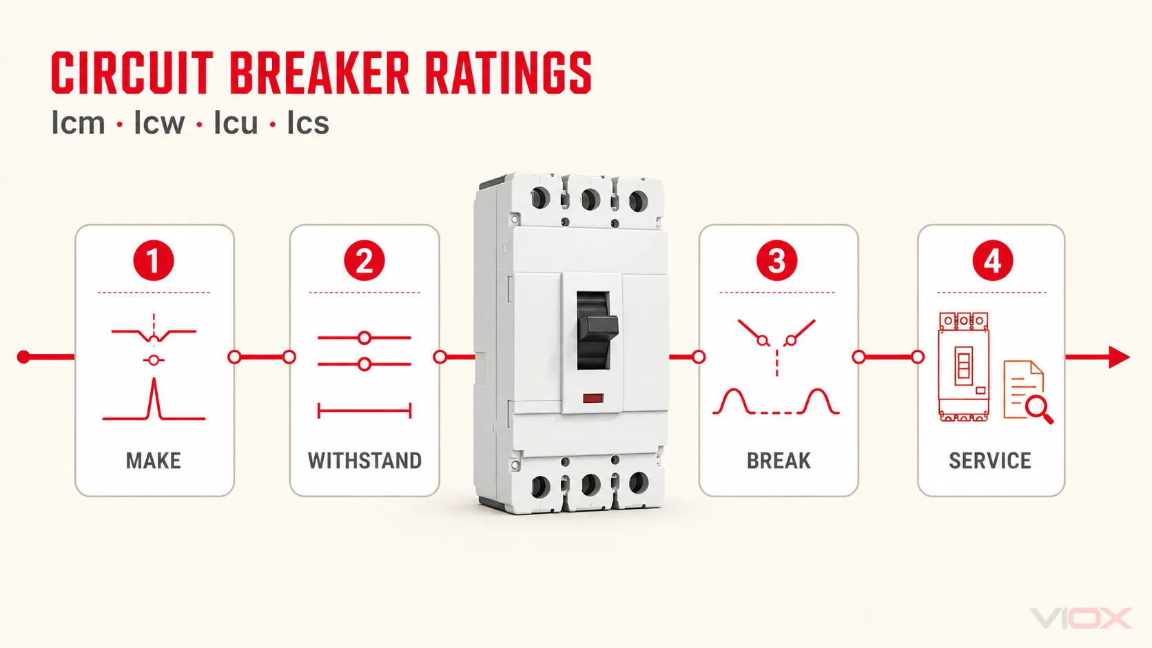
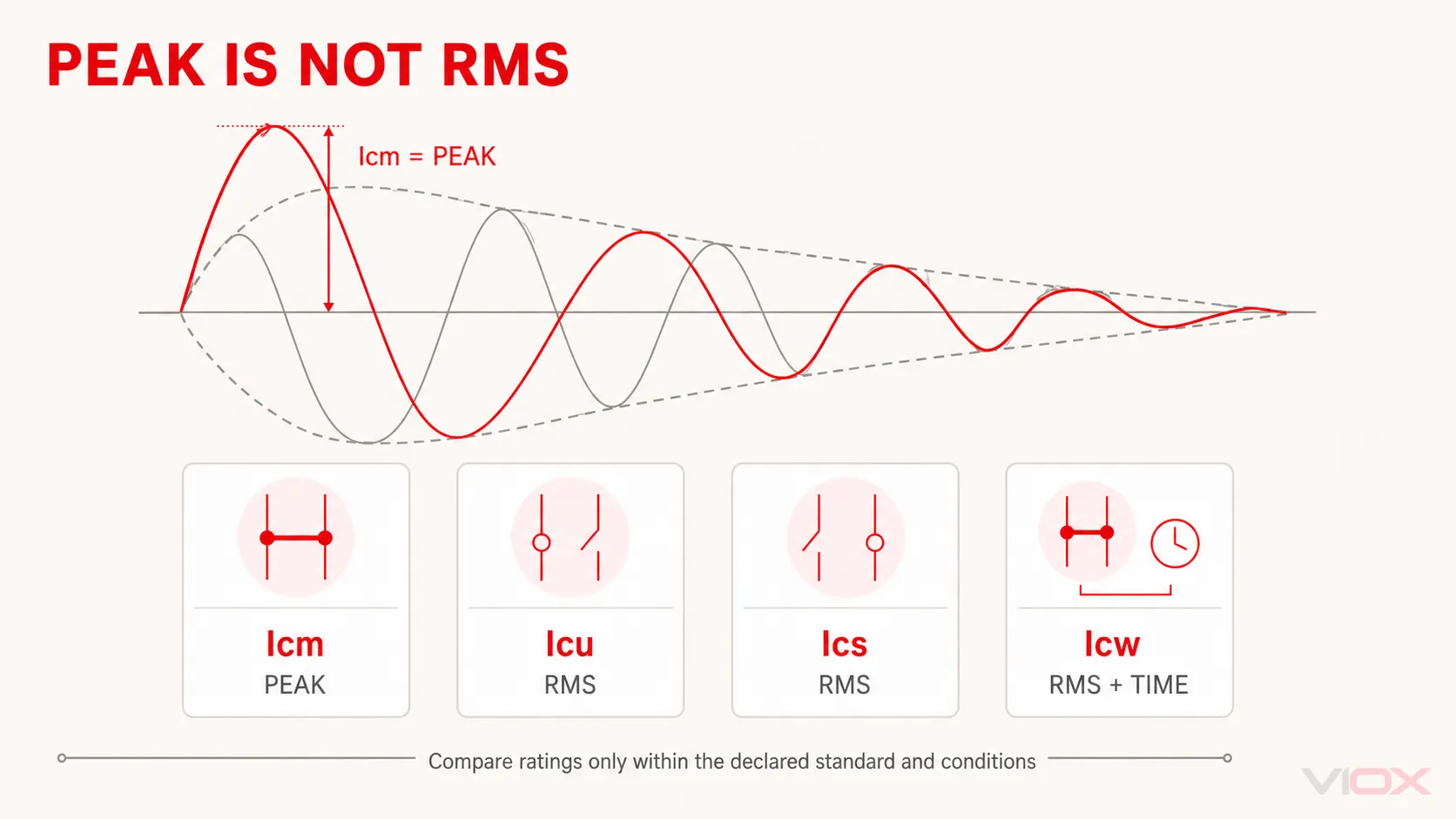
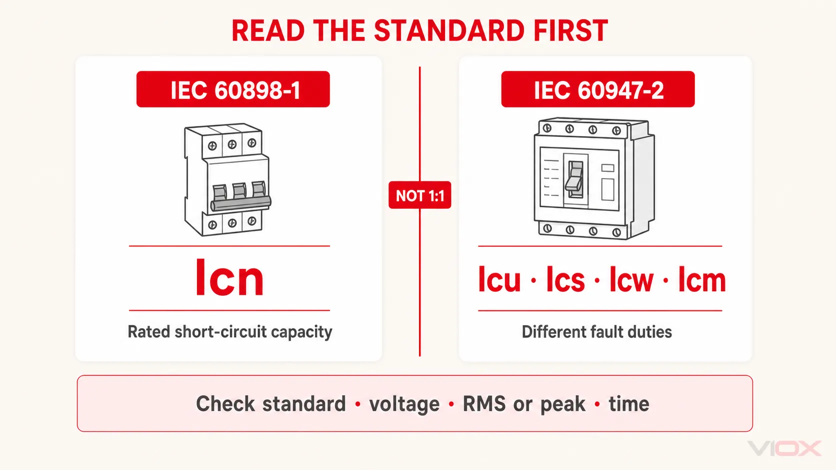
Icn, Icu, Ics, Icw, and Icm describe different short-circuit duties; they are not five names for the same breaker rating. Icn is used primarily for household and similar circuit breakers under IEC 60898-1. Icu, Ics, Icw, and Icm are defined in the IEC 60947-2 industrial circuit-breaker framework. Read each value together with its product standard, rated voltage, current basis, and—where applicable—time duration.
| Rating | Meaning | What it tells you | Current basis | Main standards context |
|---|---|---|---|---|
| Icn | Rated short-circuit capacity | The short-circuit capacity declared for a household or similar circuit breaker | Prospective current under the applicable test sequence | IEC 60898-1 |
| Icu | Rated ultimate short-circuit breaking capacity | The maximum prospective short-circuit current the breaker is rated to interrupt under the specified ultimate test duty | kA RMS | IEC 60947-2 |
| Ics | Rated service short-circuit breaking capacity | The fault level at which the prescribed service breaking sequence and subsequent checks are performed | kA RMS or percentage of Icu | IEC 60947-2 |
| Icw | Rated short-time withstand current | The current the breaker can carry for a declared short time under specified conditions | kA RMS plus time | IEC 60947-2 |
| Icm | Rated short-circuit making capacity | The peak current the breaker can make when closing onto a short circuit under specified conditions | kA peak | IEC 60947-2 |
The practical rule is simple: first identify the product standard, then compare like with like. A peak Icm value cannot be compared directly with an RMS Icu value, and an Icw value is incomplete without its time.
One Fault, Four Different Breaker Duties
A breaker may face several distinct duties during a short circuit:
- It may have to interrupt the fault.
- It may need to remain suitable for continued service after a prescribed interruption sequence.
- An upstream breaker may intentionally withstand the fault for a short delay while a downstream device clears it.
- It may be commanded to close onto an existing fault.
These duties produce different thermal, dielectric, mechanical, and arc-interruption stresses. That is why one headline kA number cannot describe every aspect of industrial breaker performance.
The current edition of IEC 60947-2:2024 applies to circuit breakers intended to be installed and operated by instructed or skilled persons, within the voltage scope stated by the standard. The terms on a datasheet must therefore be interpreted within that product-standard context—not as universal labels for every protective device.
Icu vs Ics: Ultimate Interruption and Service Performance
Icu is the ultimate short-circuit breaking capacity. It answers the first safety question: can the breaker interrupt the specified prospective short-circuit current at the declared operating voltage under the standard’s ultimate breaking test sequence?
If the prospective short-circuit current at a switchboard is 38 kA, a breaker whose applicable Icu is only 25 kA is not adequate at that location. A 50 kA value may satisfy this first check only if it applies to the actual voltage, frequency, poles, installation arrangement, and product standard.
Icu does not mean the breaker can be returned to service automatically after a severe fault. Inspection, testing, servicing, or replacement may still be required according to the manufacturer’s instructions and the site’s post-fault procedure.
Ics is the service short-circuit breaking capacity. It is often stated as a percentage of Icu, but the percentage must be converted back to the actual kA value before it is compared with the system fault level.
| Datasheet declaration | Correct reading |
|---|---|
| Icu = 50 kA; Ics = 25 kA | Service capacity is 25 kA, or 50% of Icu |
| Icu = 50 kA; Ics = 37.5 kA | Service capacity is 37.5 kA, or 75% of Icu |
| Icu = 50 kA; Ics = 50 kA | Service capacity equals Icu |
The engineering distinction is therefore:
- Icu: ultimate interruption capability under the specified test duty.
- Ics: service breaking performance verified at a declared fault level under the prescribed test duty and follow-up checks.
Do not reduce this to “Icu survives once, Ics survives repeatedly.” The test sequences and verification requirements are defined by the applicable standard, and post-fault field decisions still follow manufacturer instructions. Schneider Electric’s Ics technical explanation similarly treats Ics as a service-performance characteristic rather than a blanket reuse guarantee.
Icw: Short-Time Withstand Current Must Include Time
Icw is the rated short-time withstand current. It becomes important when an upstream breaker intentionally delays opening so that a downstream protective device has time to clear the fault first.
During that delay, the upstream breaker remains closed and carries the fault current. Its Icw duty must therefore be coordinated with both:
- the expected short-circuit current at that point; and
- the selected short-time delay.
| Declaration | What may be compared |
|---|---|
| Icw = 20 kA for 0.5 s | A duty not exceeding 20 kA for the declared 0.5-second condition |
| Icw = 20 kA for 1 s | A different, more demanding time duty than 20 kA for 0.5 s |
Never quote “Icw = 20 kA” and omit the duration. Schneider Electric’s definition of Icw likewise defines it as a manufacturer-assigned current that equipment can carry without damage under specified test conditions and expresses it together with time.
Icw is associated particularly with breakers intended for time-delayed selectivity. It is not a substitute for checking the manufacturer’s selectivity and backup-protection tables for the exact upstream/downstream combination. Trip-unit settings, instantaneous overrides, current-limiting behavior, and the tested breaker pairing can all change the result. See the guide to MCCB trip-unit settings for the Ir, Isd, and Ii functions involved.
Icm: Peak Current When Closing Onto a Fault
Icm is the rated short-circuit making capacity. It describes the peak current a breaker can establish when its contacts close onto a short circuit under specified conditions.
This is mechanically different from breaking a fault. The first asymmetrical current peak can create high electrodynamic forces in the contacts, conductors, operating mechanism, and enclosure. Consequently:
- Icm is expressed as a peak value;
- Icu and Ics are expressed using RMS short-circuit current;
- the numerical Icm value is normally higher, but that does not make it a “better Icu.”
IEC-based tables may relate Icm to the corresponding breaking capacity using a factor determined by the applicable test conditions and power factor. Do not apply one fixed multiplier to every breaker, voltage, standard, or AC/DC duty. Use the value declared by the manufacturer for the exact product, or the relationship required by the applicable edition of the product standard.
Icm deserves explicit attention where the breaker can be closed remotely or automatically, such as an incomer, bus coupler, or transfer arrangement. Whether the system may actually reclose after a fault is a separate control and protection decision.
Icn vs Icu: Why MCB Labels Use Different Terms
Many searches for Icu vs Ics begin with an MCB marked 6000 or 10000. The label can only be interpreted correctly after identifying the standard printed on the device or datasheet.
IEC 60898-1:2015+A1:2019 covers AC air-break circuit breakers for household and similar installations within its declared limits, including rated voltage up to 440 V, rated current up to 125 A, and rated short-circuit capacity up to 25 kA. In that context, the central short-circuit term is Icn.
IEC 60947-2 covers industrial circuit breakers operated by instructed or skilled persons and uses Icu and Ics, with Icw and Icm relevant to their defined duties.
| If the product is declared to… | Start with… | Do not assume… |
|---|---|---|
| IEC 60898-1 | Icn and the device marking/datasheet | That the printed kA value is an IEC 60947-2 Icu |
| IEC 60947-2 | Icu and Ics at the actual voltage | That Icu alone guarantees post-fault continued service |
| Both standards | Each rating under its own test framework | That numerically equal ratings are interchangeable |
| UL 489 or another North American standard | The applicable interrupting rating and product certification | That IEC Icu, Ics, or Icn converts one-to-one to the North American rating |
For a fuller standards comparison, read IEC 60898-1 vs IEC 60947-2. For the meaning of a generic kA label, use the circuit-breaker kA rating guide.
Why Many MCBs Do Not Show a Separate Icm Marking
The absence of a separate making-current number on an IEC 60898-1 MCB does not mean making duty was ignored. It means the product is marked and selected according to the requirements and declared ratings of that standard, whose main user-facing short-circuit capacity is Icn.
Three cautions prevent a common misreading:
- Do not relabel Icn as Icu or Ics. Those terms belong to a different standards context unless the product is also declared to IEC 60947-2.
- Do not infer one universal Icm multiplier. The peak relationship depends on the standard’s test conditions and the declared product data.
- Do not add a generic safety factor to compensate for missing Icm. Determine the prospective short-circuit current, identify the applicable rating and voltage, and use verified manufacturer data or tested coordination information.
For ordinary MCB selection, the primary check is that the applicable short-circuit capacity is not less than the prospective short-circuit current at the installation point, subject to local rules and any verified backup-protection arrangement. The separate 6 kA vs 10 kA MCB selection guide owns that practical decision.
Five-Step Circuit-Breaker Rating Check
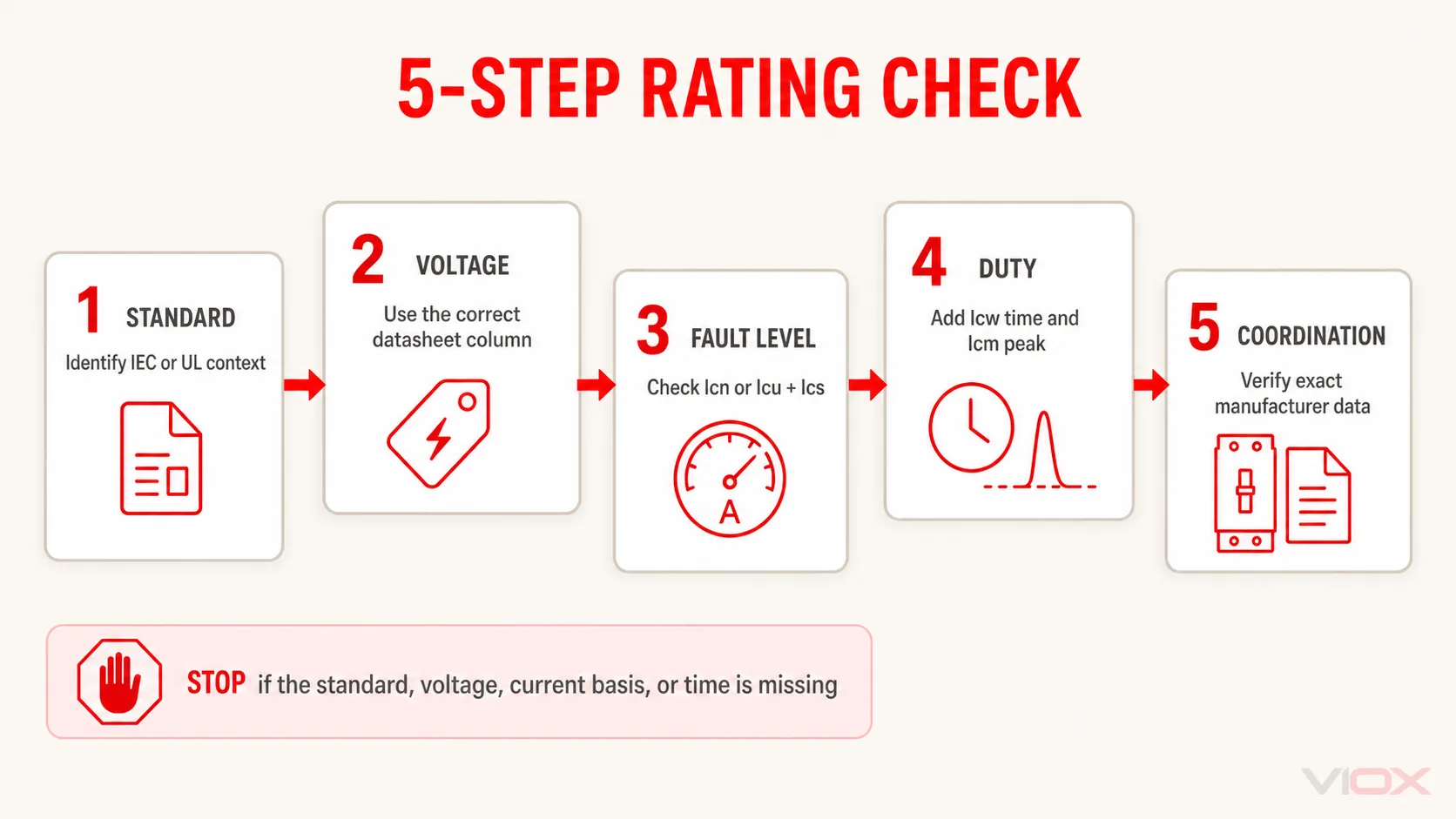
Use this sequence when reading an MCB, MCCB, or ACB datasheet.
1. Identify the product standard
Find the exact standard and edition declared by the manufacturer. This determines which rating vocabulary and test framework apply.
2. Match the rated voltage
Breaking capacities can change with operational voltage. Compare the system voltage with the correct datasheet column; do not carry a kA value from one voltage to another.
3. Compare the correct breaking rating with fault level
For an IEC 60898-1 device, check Icn. For an IEC 60947-2 device, check Icu and then Ics. The prospective short-circuit current must be determined for the actual installation point.
4. Add time and peak-duty checks when the system requires them
If selective delay is intentional, verify Icw at the required time. If closing onto a fault is credible, verify Icm. Do not compare peak and RMS values directly.
5. Verify the exact assembly and coordination data
Check poles, frequency, trip unit, accessories, enclosure or assembly limits, and the manufacturer’s published selectivity or cascading tables. Two breakers with individually adequate ratings do not automatically form a verified coordinated pair.
Two Worked Reading Examples
Example 1: Household-Type MCB
An MCB is marked C20 and 6000 and is declared to IEC 60898-1. C20 identifies the type-C instantaneous characteristic and 20 A rated current in that marking system; 6000 indicates a 6 kA short-circuit capacity under the stated standard conditions. Do not rewrite the 6 kA marking as IEC 60947-2 Icu unless the manufacturer’s documentation separately declares that rating.
Whether 6 kA is sufficient depends on the prospective short-circuit current at the actual installation point. The label alone cannot answer that system question.
Example 2: Industrial MCCB
An MCCB datasheet gives, at the project’s operating voltage, Icu = 50 kA, Ics = 25 kA, and Icw = 20 kA for 1 s. Read these as three different duties:
- it has a declared 50 kA ultimate breaking capacity;
- its service breaking capacity is 25 kA;
- it has a declared 20 kA short-time withstand duty for 1 second.
If a coordination study requires the upstream breaker to carry 24 kA for 1 second, the stated Icw does not satisfy that duty even though Icu is 50 kA. The remedy is not to compare Icu with the delay current; select an appropriate breaker/setting combination and verify it from manufacturer coordination data.
Frequently Asked Questions
What is the main difference between Icu and Ics?
Icu is the ultimate short-circuit breaking capacity. Ics is the service short-circuit breaking capacity verified under a different prescribed sequence and follow-up checks. Icu establishes ultimate interruption capability; Ics provides the more relevant service-performance reference at its declared fault level.
What does Icw mean on an MCCB or ACB?
Icw is rated short-time withstand current. It must be read as a current plus a duration, such as a declared kA value for 0.5 or 1 second. It matters when the breaker intentionally delays for selectivity.
Is Icm always 2.2 times Icu?
No. Do not use 2.2 as a universal conversion. The relationship depends on the applicable standard, test conditions, power factor, rating range, and product declaration.
Can I compare Icn and Icu directly?
Not from the number alone. Both concern short-circuit interruption, but IEC 60898-1 and IEC 60947-2 use different product scopes and test frameworks. Compare each rating only within the standard, voltage, and product declaration that produced it.
Can a breaker be reused after interrupting a fault at Icu?
Do not assume so. Follow the manufacturer’s inspection, testing, servicing, and replacement instructions after a severe short circuit. Ics is the more relevant service-performance rating, but it is not permission to skip a post-fault assessment.
Sources
- IEC 60947-2:2024 — Low-voltage switchgear and controlgear, Part 2: Circuit-breakers
- IEC 60898-1:2015+A1:2019 — Circuit-breakers for overcurrent protection for household and similar installations
- Schneider Electric — Service breaking capacity (Ics)
- Schneider Electric — Rated short-time withstand current (Icw)
For product evaluation after the standard and fault duties are defined, see the VIOX MCCB range or contact [email protected] with the system voltage, prospective short-circuit current, required Ics, and any short-time-delay duty.