On this page
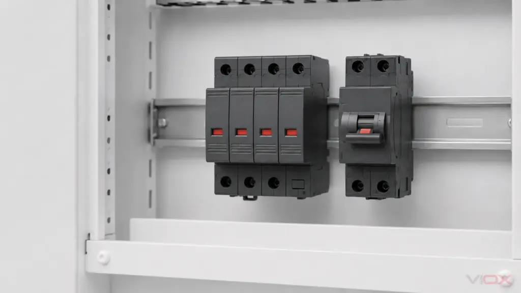
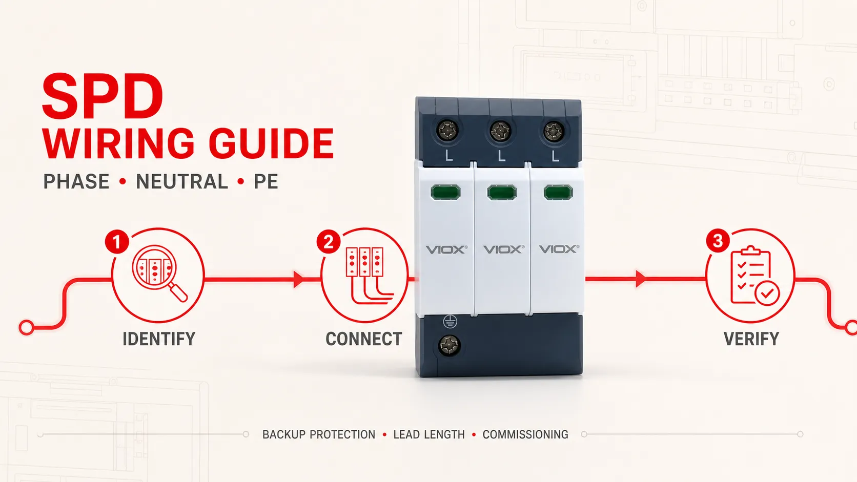
An AC surge protective device (SPD) is normally connected in parallel with the circuit it protects. Correct wiring means more than putting each conductor into a matching terminal: the installer must confirm the supply and earthing system, use the exact manufacturer’s connection diagram, provide the required short-circuit protection, minimize the complete surge-current path and verify the finished assembly before energization.
There is no safe universal SPD wiring diagram. A single-phase TN-S board, a three-phase four-wire TT board and a TN-C section with a PEN conductor do not use the same protection modes. The following workflow is for qualified personnel working under the applicable installation rules and the device and panel manufacturers’ instructions.
Safety boundary: Isolate the installation, secure it against reconnection and verify absence of voltage using the approved local procedure before opening or modifying a panel. This guide does not authorize live work. Conductor sizes, torque values and protective-device ratings must come from the project documents and the exact product instructions.
SPD Wiring at a Glance
Before any conductor is cut, record these six inputs:
| Required input | What to verify | Why it changes the wiring |
|---|---|---|
| System voltage | Line-to-line and line-to-neutral voltage, frequency and maximum normal condition | Determines whether the SPD’s voltage rating is suitable in each connected mode |
| Conductors present | L, L1/L2/L3, N, PE or PEN | Determines terminal count and available protection paths |
| Earthing system | TN-S, TN-C-S, TN-C, TT, IT or another defined system at this exact point | Changes permissible phase, neutral and earth connections |
| SPD diagram | Terminal labels, 3+0/4+0/3+1 arrangement and orientation | Product labels are not perfectly uniform between manufacturers |
| Fault level and upstream protection | Prospective short-circuit current, upstream fuse/breaker and manufacturer backup table | Determines whether a separate backup device is needed and whether the assembly is fault-rated |
| Installation layout | Bus connection, backup device, SPD position and PE/bonding point | Determines the effective connection length and installed protection level |
If any one of these is unknown, stop at the design stage. Selecting topology first from a product photograph is not a substitute for identifying the system.
1. Confirm the SPD and the Installation Point
First verify that the device is an AC power SPD suitable for the installation location. Its Type must match the surge exposure and coordination plan: Type 1, Type 2, Type 3 or a combined Type 1+2 designation describes test duty, not the number of poles. Use the separate Type 1 vs Type 2 vs Type 3 guide for that decision.
Then compare the manufacturer’s circuit symbol with the conductors at the intended point. Markings such as 1+1, 3+1, 1+NPE and 3+NPE often describe internal protection paths rather than only physical poles. The exact diagram is controlling; the SPD topology guide explains the terminology.
2. Understand the Parallel Branch
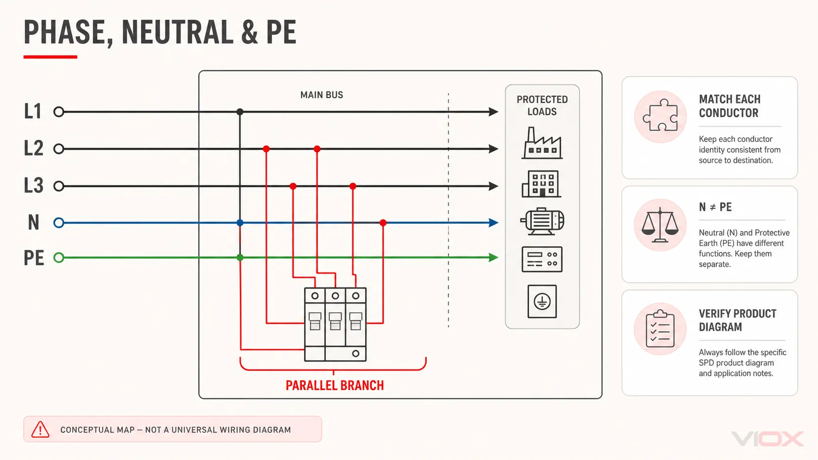
A panel SPD is generally connected as a parallel branch from the live conductor or bus to the other relevant conductors. During normal operation it should not carry the load current. During a transient, one or more protection modes conduct surge current and limit the voltage difference between conductors.
This has two practical consequences:
- Panel load amperes do not directly “size” the SPD’s surge-current rating.
- The branch connection, backup protective device and every conductor in the active surge path affect real performance.
Do not route the normal load through an SPD unless the exact product is expressly designed as a series-connected device.
3. Map Phase, Neutral and PE Correctly
Phase conductors
Connect each protected phase only to the terminal identified for that phase or live conductor. In a three-phase assembly, confirm whether all three phase modules and any neutral-earth module form one approved assembly. Do not leave a required mode unconnected or bridge terminals to imitate another topology.
Neutral
Neutral is a current-carrying conductor and is not interchangeable with PE. Where the selected topology includes L-N and N-PE protection, connect N to the designated neutral terminal and route it according to the product diagram. A three-wire system without neutral requires a topology designed for that system; adding a local “neutral” connection is not a remedy.
PE or PEN
Connect the SPD’s protective/bonding terminal to the specified PE, PEN or equipotential connection at that installation point. TN-C sections require particular care because PEN separation and downstream N/PE treatment are system design matters. Never recreate an N-PE bond merely to make an SPD diagram appear to fit.
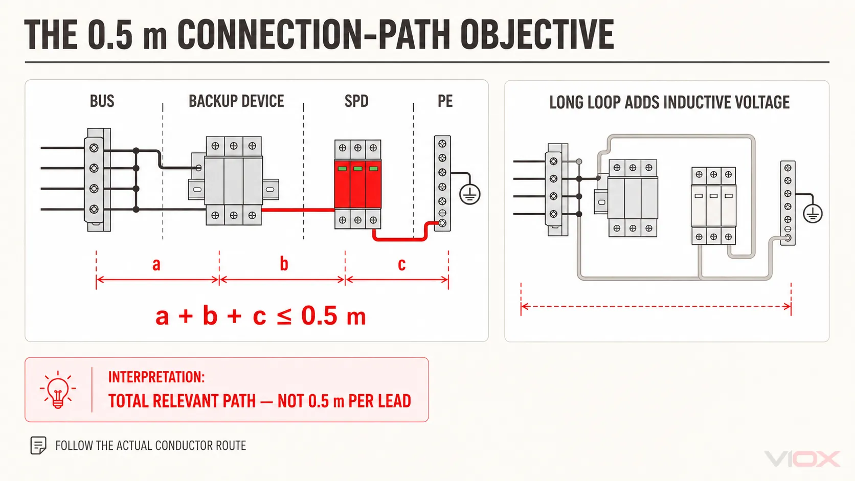
Every conductor in the surge-current loop contributes inductive voltage, so the design objective is a compact overall path—not merely a short green/yellow lead.
4. Read Common Single- and Three-Phase Arrangements
These descriptions are conceptual checks, not terminal-by-terminal instructions.
| System context | Common conceptual arrangement | Required verification |
|---|---|---|
| Single phase with L, N and PE | Protection between L-N plus an N-PE path, or protection modes defined by the selected assembly | Exact 1+1/1+NPE diagram, Uc by mode and earthing-system suitability |
| Three phase, four wire with L1/L2/L3/N/PE | Phase-to-neutral paths plus N-PE in a 3+1 arrangement, or another approved four-conductor topology | Whether 3+1, 4+0 or another scheme is specified for the earthing system |
| Three phase, three wire | Phase-to-phase and/or phase-to-PE modes as defined by the design | Delta/wye configuration, absence of neutral and actual voltage across each mode |
| TN-C section | Arrangement designed for L conductors and PEN | Location of PEN separation and product/system compatibility |
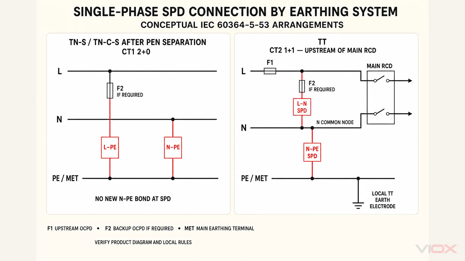
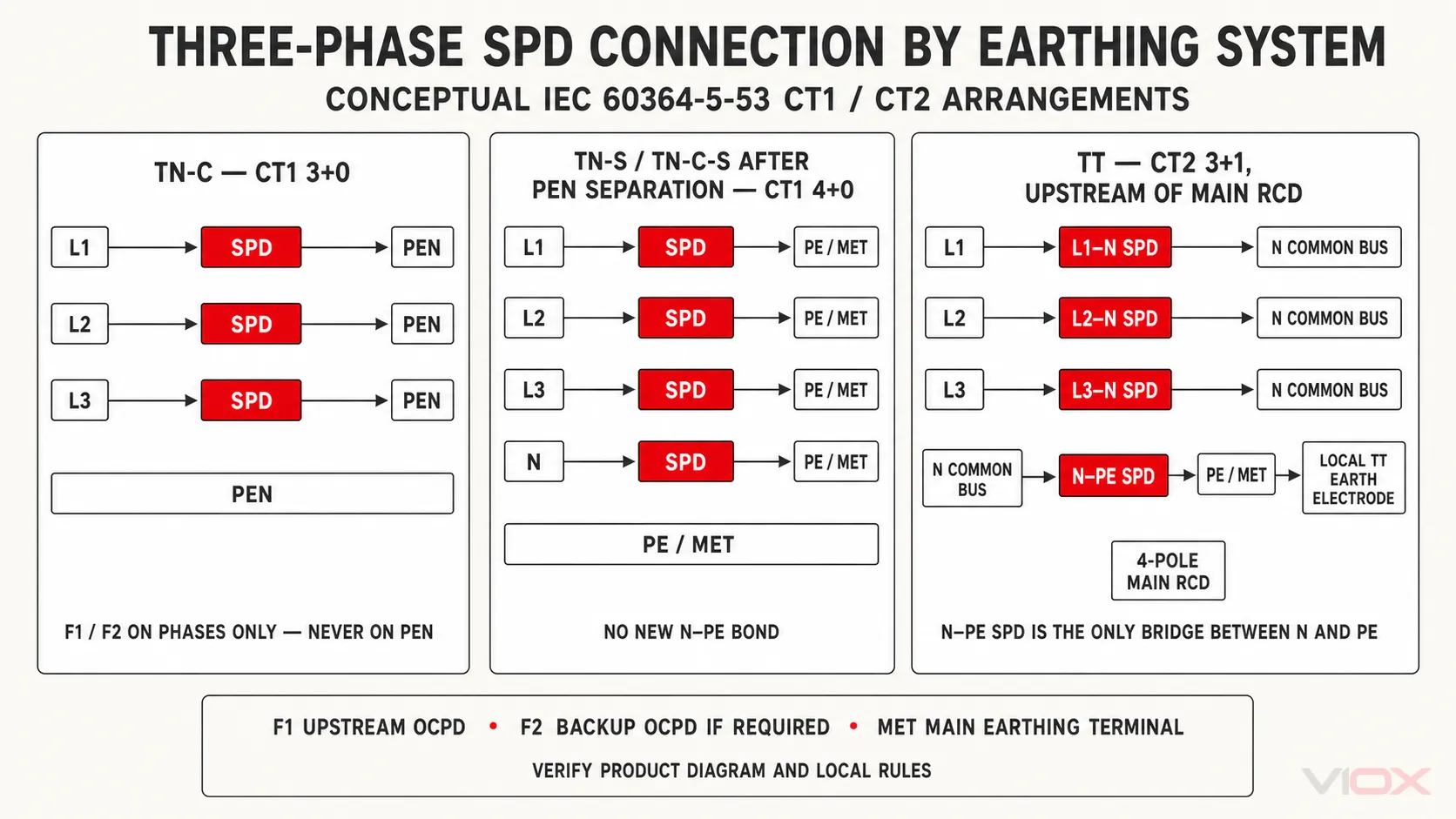
For a full topology decision, use the 1P, 1+NPE, 3P and 3+NPE guide. Do not infer protection modes from module count alone.
5. Determine Whether a Backup Fuse or Breaker Is Required
SPDs commonly contain thermal disconnecting functions that remove a failed protection component from service. That function does not automatically prove that the SPD branch can safely clear the available short-circuit current.
Use this sequence:
- Record the prospective short-circuit current at the SPD connection point.
- Identify the upstream protective device and its rating and characteristic.
- Read the SPD manufacturer’s maximum upstream protection and backup fuse/breaker coordination table.
- Confirm the SPD’s SCCR or applicable short-circuit withstand/current declaration such as Isccr.
- If the permitted upstream protection is exceeded, install the manufacturer-specified external short-circuit protective device.
- Confirm the complete branch and panel assembly remain coordinated and compliant.
The backup device is not selected from a generic online table. Fuse and circuit-breaker behavior differ, and an arbitrary smaller breaker may nuisance-operate during surge duty while an oversized device may not protect the failed branch. See Can I Connect a Surge Protector to an Existing Breaker? for the narrower coordination question.
6. Keep the Complete Surge Path Short
The tested voltage protection level Up is measured at the SPD under specified conditions. In a panel, rapid surge current through connection inductance adds dynamic voltage to the voltage seen by protected equipment. Longer leads, large loops and unnecessary bends therefore increase the installed protection level.
IEC 60364-5-53 installation guidance is commonly applied by aiming to keep the relevant total connection path of the SPD assembly at no more than 0.5 m. Interpret that correctly:
connection point → external backup device (if used) → SPD → applicable PE/PEN/N connection point
It is not an allowance of 0.5 m for each conductor, and the relevant path must be assessed for each protection mode. Follow the actual conductor route, not the straight-line distance between device housings.
Layout rules that improve performance
- Place the SPD and any dedicated backup device close to the bus and bonding point.
- Use the shortest practical, direct conductors permitted by the product and panel design.
- Avoid coils, spare loops and sharp or repeated bends.
- Keep outgoing protected conductors separated from incoming unprotected conductors where the panel design requires it.
- Use V-connections or feed-through terminal arrangements only where the manufacturer and assembly design permit them.
- Do not assume that increasing conductor cross-section cancels the inductive effect of an unnecessarily long route.
Schneider Electric similarly notes that lead length adds to let-through voltage and advises the shortest necessary routing in its SPD lead-length guidance.
7. Build the Installation in a Controlled Order
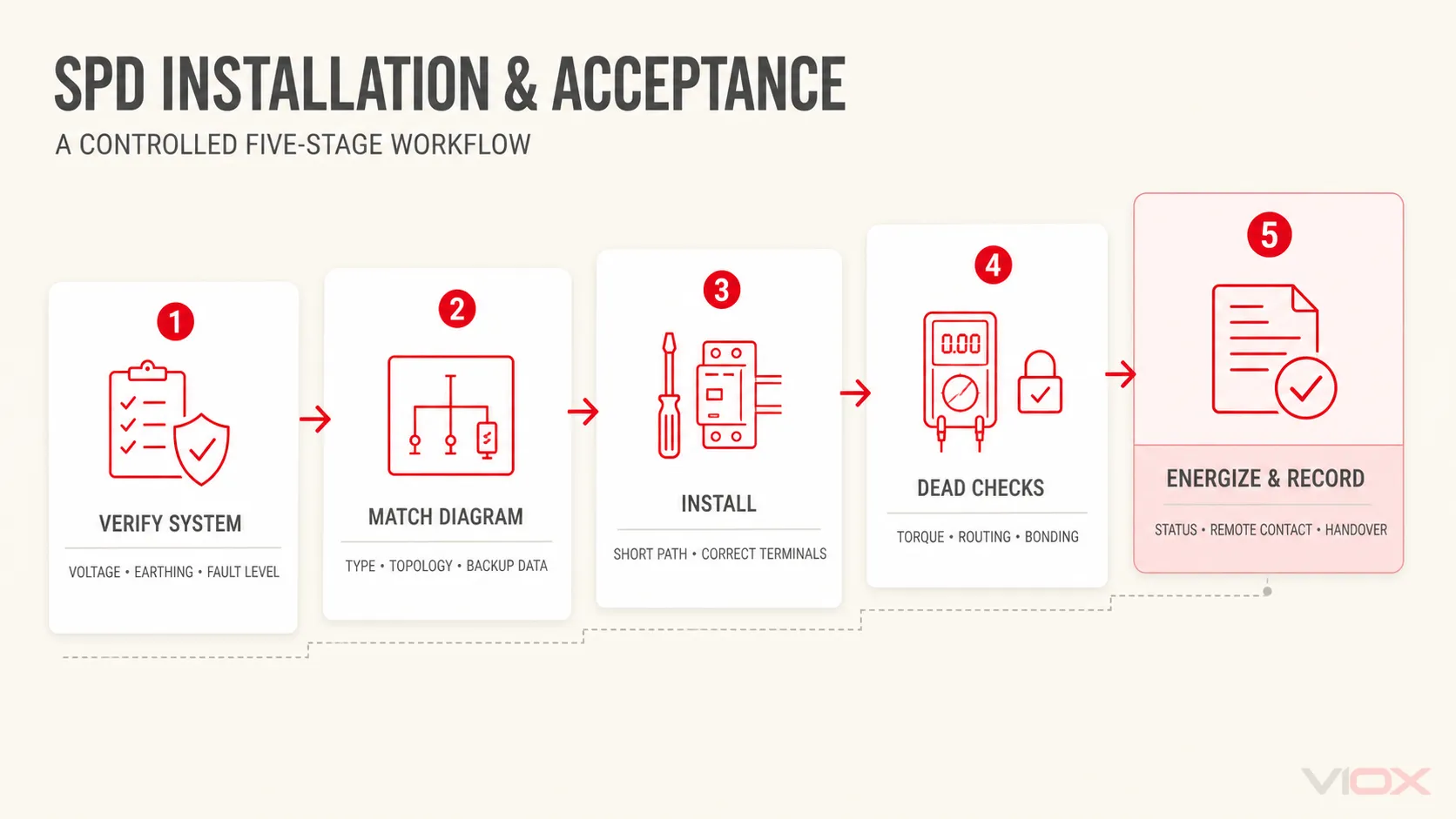
With the panel safely isolated:
- Confirm the SPD model, modules, accessories and status/remote-contact arrangement against the approved documents.
- Verify the DIN rail, enclosure space, segregation and environmental conditions.
- Position the SPD and backup device to minimize the complete connection path.
- Prepare conductors of the specified type and cross-section; do not add unnecessary service loops.
- Connect phase, neutral and PE/PEN exactly as shown in the model-specific diagram.
- Tighten every terminal to the manufacturer’s stated torque using the required method and record it where the quality plan requires.
- Connect remote signalling only to its isolated auxiliary circuit and terminal rating; it is not a surge-current conductor.
- Recheck polarity, terminal identity and conductor routing before covers are fitted.
8. SPD Acceptance and Commissioning Checklist
Before energization
- Approved single-line diagram, earthing-system identification and SPD schedule agree.
- SPD Type, Uc/MCOV, protection modes and pole arrangement match the application.
- The available fault current does not exceed the applicable short-circuit declaration.
- Upstream and dedicated backup protection match the manufacturer’s coordination data.
- Phase, neutral, PE/PEN and remote-contact conductors are on the correct terminals.
- Conductors have the specified cross-section, insulation, identification and bend radius.
- The relevant connection path is measured and recorded; any deviation from the short-path objective is reviewed.
- Terminal torque, module seating and mechanical retention are verified.
- PE/bonding continuity checks are completed using the authorized dead-test procedure.
- No insulation-resistance or dielectric test is applied through a connected SPD unless the manufacturer expressly permits the method.
After energization
- Energize under the approved commissioning procedure.
- Confirm normal phase/voltage conditions and the SPD’s visual status indication.
- Verify remote alarm contact logic at the monitoring system where fitted.
- Check for abnormal indication, sound, odor or temperature and de-energize if a fault is suspected.
- Record device model, serial/batch identification, installation date, backup device, measured lead path and initial status.
- Label replacement modules and inspection responsibility.
A multimeter check cannot demonstrate the SPD’s impulse clamping performance. Field acceptance confirms correct selection, connection and status; product surge performance comes from the declared standardized tests.
Handover and Maintenance
Provide the final single-line diagram, product datasheet, installation instructions, backup-protection record and commissioning checklist. Make the status window visible for inspection and explain what a red or failed indication requires. Inspection frequency should follow the maintenance plan, site exposure and manufacturer guidance, with additional checks after known lightning events or electrical disturbances.
If an installed device repeatedly disconnects, shows a failed indicator or causes protective-device operation, do not simply fit a larger breaker. Isolate the circuit and investigate system voltage, TOV exposure, earthing, fault level, coordination and installation quality using the SPD installation mistakes guide.
Final Wiring Record
Before ordering or approving an SPD installation, the project file should answer:
- What are the line-to-line and line-to-neutral voltages?
- What earthing system exists at this panel?
- Which protection modes and topology are required?
- Which SPD Type and ratings were specified?
- What is the prospective short-circuit current?
- Which upstream or dedicated backup device is approved by the manufacturer?
- What is the longest relevant connection path?
- Where is PE/PEN connected?
- How will status and remote indication be verified?
For model-level support, send this record and the single-line diagram with your enquiry to the VIOX SPD product team.