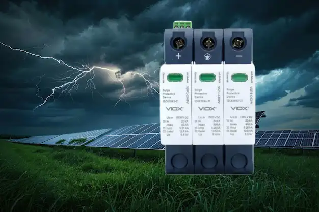
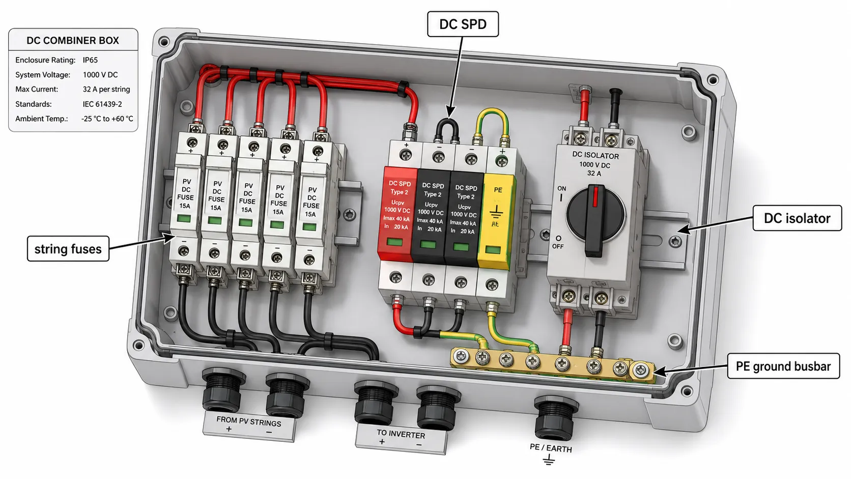
What is a DC surge protection device, and how do you select the right one?
A DC surge protection device (DC SPD) diverts transient overvoltage on a direct-current bus to ground, protecting inverters, chargers, and batteries. Select it by matching maximum continuous voltage (Ucpv) above the system’s worst-case voltage, choosing Type 1 or Type 2 by lightning exposure, and verifying the governing standard—IEC 61643-31 for PV, IEC 61643-11 for EV, BESS, and industrial DC.
A correctly specified DC SPD is not interchangeable with its AC counterpart, and the standard that applies depends entirely on the application. This guide sets out the parameters, the standards, and the application boundaries that decide whether a device protects equipment reliably or fails in service.
Key Takeaways
- DC is not AC. A DC arc does not self-extinguish at a voltage zero-crossing, so an AC SPD offers no safe protection on a DC bus and can fail dangerously. Always use a DC-rated device sized for the bus voltage.
- The standard follows the application. IEC 61643-31 covers only the DC side of photovoltaic generators and inverters up to 1500 V DC. Battery and capacitor storage are explicitly excluded, so BESS, EV, and industrial DC devices are qualified to the general standard IEC 61643-11.
- Five parameters decide the choice: Ucpv, In, Imax, Iimp, and Up. Get Ucpv and Up right first—the rest is coordination.
- IEC Type ≠ UL Type. IEC types describe a surge test class; UL 1449 types describe the permissible installation location relative to the service disconnect.
- Installation determines performance. Short leads, correct connection mode for the system earthing, and backup overcurrent protection matter as much as the device rating.
Why DC surge protection is not the same as AC
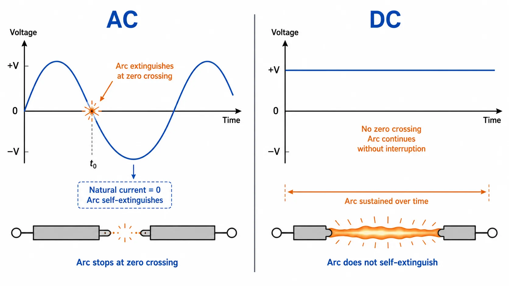
In an AC circuit, current crosses zero one hundred or one hundred twenty times per second, and any arc drawn across a clearing contact is naturally quenched at that crossing. A direct-current bus never crosses zero. Once an arc establishes inside a degrading surge protective device, it will sustain itself until something interrupts the energy path. This single physical difference drives the entire design of a DC SPD: the metal-oxide varistor (MOV) must withstand a continuous unidirectional voltage rather than an alternating one, and the device needs an integrated DC disconnection or arc-extinguishing mechanism that an AC unit does not provide.
The practical consequence is firm. An AC SPD installed on a PV string, a battery bus, or a DC fast-charger output is not merely sub-optimal—it is a fire risk. The voltage ratings, the MOV chemistry, and the end-of-life disconnect behaviour are all built around AC waveforms that the DC circuit will never present.
The standards that actually apply
The most common specification error in DC surge protection is applying the wrong standard to the application. The table below sets the boundaries precisely.
| Standard | Scope | Applies to |
|---|---|---|
| IEC 61643-31 | Requirements and test methods for SPDs on the DC side of PV installations ≤ 1500 V DC | PV arrays and inverter DC inputs only—battery and capacitor storage are explicitly excluded |
| IEC 61643-32 | Selection and application principles for PV SPDs (risk assessment, earthing, coordination) | PV system design and placement |
| IEC 61643-11 | General requirements and test methods for SPDs on low-voltage power systems (≤ 1000 V AC / 1500 V DC) | EV charging DC, BESS DC, industrial and telecom DC |
| UL 1449 | North American safety standard for surge protective devices | AC and DC SPDs sold into UL-governed markets |
The exclusion written into IEC 61643-31 is the detail most guides miss: a device “compliant with IEC 61643-31” is qualified for a PV generator, not for the battery bank beside it. You can confirm the scope directly in the IEC 61643-31 standard listing. IEC 61643-32 then governs how PV SPDs are selected and placed—risk assessment, the effect of system earthing on connection mode, and coordinated protection schemes.
A note on Type numbers. An IEC Type 1 device is tested with a 10/350 µs impulse current (Iimp) that simulates a direct lightning strike; an IEC Type 2 is tested with an 8/20 µs nominal discharge current (In) representing induced and switching surges. UL 1449 uses the same digits to mean something entirely different: a UL Type 1 may be connected on the line side of the service disconnect without external overcurrent protection, a UL Type 2 sits on the load side, and a UL Type 3 is a point-of-utilization device. When sourcing across IEC and UL markets, confirm both designations explicitly; this comparison of surge protection standards — IEC 61643 vs UL 1449 vs GB 18802 maps the equivalences.
Core selection parameters
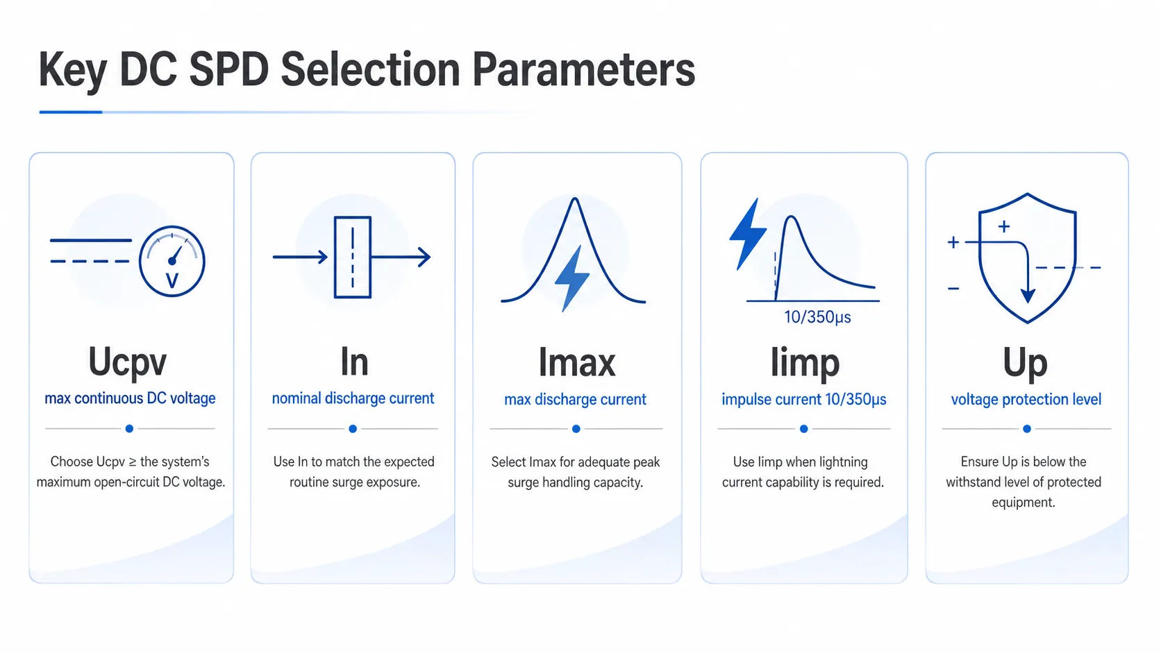
Five ratings govern whether a DC SPD survives and whether it actually protects the load. Read them in this order.
| Parameter | Symbol | Meaning | Selection rule |
|---|---|---|---|
| Max. continuous operating voltage | Uc / Ucpv | Highest steady DC voltage the SPD tolerates indefinitely | ≥ the worst-case system voltage; for PV, a common convention is Ucpv ≥ 1.2 × array Voc at the coldest site temperature |
| Nominal discharge current | In | 8/20 µs surge the SPD survives repeatedly | Match to expected induced-surge frequency (20 kA is typical) |
| Max. discharge current | Imax | Largest single 8/20 µs surge a Type 2 device handles | Provide headroom above In for high-exposure sites |
| Impulse current | Iimp | 10/350 µs direct-lightning charge for Type 1 devices | Required where a lightning protection system exists; ~12.5 kA/pole covers nearly all systems |
| Voltage protection level | Up | Let-through voltage at the terminals during a surge | At least 20% below the protected equipment’s impulse withstand voltage |
The two parameters engineers most often get wrong are Ucpv—the maximum continuous operating voltage—and Up. Set Ucpv too low and the device treats normal operating voltage as a fault, overheats, and ages prematurely. The trap in PV is temperature: a module’s open-circuit voltage rises as the cell cools, so the worst-case array voltage occurs on the coldest clear morning, not at the nameplate rating. Set Up too high and the surge passes through to equipment whose insulation cannot withstand it. Where In and Imax get conflated, this guide to Imax vs In ratings clarifies the repetitive-versus-single-shot distinction.
Application-specific selection
Solar PV
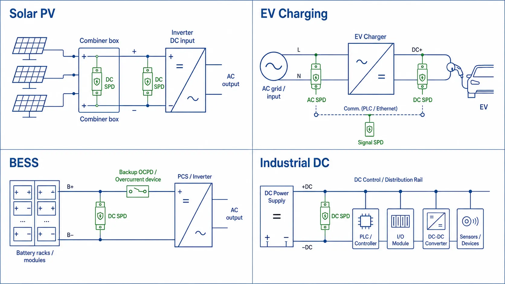
PV is the only one of the four applications fully covered by IEC 61643-31 and 61643-32. Devices are normally Type 2, mounted in the DC combiner box and at the inverter DC input to clamp induced and switching surges. Where the site has an external lightning protection system or direct-strike exposure—ground-mounted arrays especially—a Type 1 (or combined Type 1+2) device is required on the DC side. Two decisions are unique to PV: sizing Ucpv against the cold-temperature voltage rise described above, and choosing the connection mode from the array’s earthing. A floating (IT) array typically needs a three-pole device (+ / − / PE) in a Y-configuration; a system with an earthed pole often uses two poles (active / PE), but only after the fault scenarios are checked. A full PV-side workflow is set out in the VIOX guide on choosing the right SPD for a solar power system.
EV charging
A DC fast charger is a mixed environment: an AC supply, a high-voltage DC output bus, and communication and metering lines, all in an outdoor enclosure exposed to lightning and grid disturbance. Protection is therefore layered, not single-point. The AC input takes a Type 1 or Type 2 AC SPD; the DC output bus takes a DC SPD rated for the charger voltage (commonly up to ~1000 V); and the communication lines take a signal SPD matched to the actual interface. EV DC protection is qualified under IEC 61643-11, not 61643-31—the charger’s DC bus is not a PV generator. The combined surge-and-fuse scheme for these units is detailed in the DC fast charger protection guide.
BESS (battery energy storage)
This is where the standards boundary bites hardest. Because IEC 61643-31 explicitly excludes energy storage, a BESS DC SPD is qualified to IEC 61643-11. The engineering difference is not bureaucratic: a battery bank is a low-impedance, high-energy source with a very large prospective short-circuit current, where a PV array is current-limited. A DC SPD on a battery bus must therefore have adequate follow-current interrupting capability and a correctly sized backup overcurrent device, or a fault that begins as a surge event can escalate. Specify the short-circuit withstand and the recommended backup fuse from the device datasheet; do not assume a PV-rated part transfers to a 1500 V battery cabinet. For coordinated DC, AC, and signal-side protection of a storage system, see the dedicated BESS surge protection selection guide.
Industrial and telecom DC
Industrial DC covers control systems, DC drives, PLC racks, and telecom busbars such as −48 V, alongside higher 110 V and 220 V DC control voltages. These are governed by IEC 61643-11. The recurring mistake is matching the SPD to a generic “DC” label rather than to the actual bus voltage and continuity requirement. Select Uc for the specific rail, use Type 2 for normal indoor distribution, and step up to Type 1 only where the line is exposed to direct-strike energy.
| Application | Max DC voltage | Governing standard | Typical SPD type | Key engineering concern |
|---|---|---|---|---|
| Solar PV | 1000–1500 V | IEC 61643-31 + -32 | Type 2; Type 1+2 with LPS | Ucpv vs cold-temperature Voc rise; connection mode; DC arc extinction |
| EV charging (DC fast) | up to ~1000 V | IEC 61643-11 | Type 2 on DC; Type 1/2 on AC | Layered AC + DC + signal protection; outdoor exposure |
| BESS | up to 1500 V | IEC 61643-11 (not -31) | Type 2 / Type 1+2 | High prospective short-circuit current; follow-current and backup OCPD |
| Industrial / telecom DC | 48–1500 V | IEC 61643-11 | Type 2 (Type 1 if exposed) | Match Uc to the actual rail; continuity of control |
Installation and coordination
A correctly chosen device still underperforms if it is wired poorly. The dominant loss mechanism is lead inductance: during a fast-rising surge, even a short length of connecting wire develops a substantial inductive voltage that adds to Up. Keep the total connecting lead length as short as possible—ideally under 0.5 m. When SPDs are cascaded (for example a Type 1 upstream and a Type 2 near the inverter), maintain at least 10 m of cable between stages or fit a decoupling inductor of around 15 µH so the two devices coordinate rather than fight.
Provide a backup overcurrent device—fuse or breaker—sized per the SPD datasheet so the device disconnects safely at end of life, and confirm a low-impedance earth, because a poor ground both defeats the SPD and raises touch-voltage risk. In PV combiner boxes, the SPD works alongside, not in place of, isolation and overcurrent devices; how those roles divide up is set out in PV DC protection explained: MCBs, fuses, and SPDs vs RCDs, and the isolation-versus-interruption boundary in the VIOX comparison of DC isolators versus DC circuit breakers.
Maintenance and end of life
A DC SPD is a sacrificial component: each surge it absorbs consumes a little of its life. Most quality devices carry a visual status window—green for healthy, red for end of life—and many use a pluggable cartridge so a depleted module is replaced without rewiring. Inspect the indicator on a regular schedule, and replace a cartridge after the indicator flags, after any known major surge or lightning event, or at the end of its rated life. Typical service life runs roughly 10–15 years in moderate environments and shorter in high-lightning regions; treat the indicator, not the calendar, as the decisive trigger.
Frequently asked questions
Can I use an AC SPD on a DC circuit?
No. A DC arc does not self-extinguish at a zero-crossing, so a device without DC-rated disconnection can fail dangerously. Always use a DC SPD rated for the bus voltage.
Does IEC 61643-31 cover battery storage?
No. It applies only to the DC side of PV generators and inverters up to 1500 V DC; battery and capacitor storage are explicitly excluded, so BESS DC SPDs are qualified to the general standard IEC 61643-11.
Type 1 or Type 2 for solar?
Use Type 2 at the combiner box and inverter DC input for induced and switching surges. Add Type 1 (or Type 1+2) where an external lightning protection system or direct-strike risk exists. The full Type 1 vs Type 2 vs Type 3 breakdown explains the test classes behind each.
How do I set Ucpv for a PV array?
Size it above the array’s worst-case open-circuit voltage. Because module Voc rises as temperature falls, use the coldest expected ambient—a common convention is Ucpv ≥ 1.2 × array Voc at STC.
Two-pole or three-pole DC SPD?
It depends on the earthing. Floating (IT) arrays typically need three-pole (+ / − / PE); systems with an earthed pole often use two-pole, after the fault behaviour is verified.
For DC SPD specifications, Type 1, Type 2, and Type 1+2 options, and IEC/UL documentation across PV, EV, BESS, and industrial DC applications, see the VIOX DC and AC surge protection device range.
