VIOX Electric
Language

Month: July 2025

  • What Is a Consumer Unit? Components, Types, and Protection

    What Is a Consumer Unit? Components, Types, and Protection

    A consumer unit is a low-voltage distribution board that receives an incoming electrical supply and divides it into protected outgoing circuits. It provides a common enclosure for the main switching device, distribution system, terminals, and protective devices serving circuits such as lighting, socket outlets, heating, cooking equipment, or dedicated loads.

    The term is used mainly in the United Kingdom and related markets. Elsewhere, similar equipment may be called a distribution board, breaker panel, panelboard, load centre, or fuse box. These names are not always technically interchangeable because product standards, supply systems, device formats, and installation rules differ by market.

    The consumer unit itself is not one universal protective device. Its protection depends on the components installed inside the verified assembly.

    Where the Consumer Unit Sits in the Electrical System

    In a typical installation, electrical energy passes through the supply and metering equipment before reaching the consumer unit. The consumer unit then distributes that supply to separate final circuits.

    Supply → metering and service equipment → consumer unit → outgoing circuits → connected loads

    The exact ownership and isolation boundaries vary by country and utility. Supply-company equipment, meters, service fuses, isolators, and the consumer’s installation must not be treated as one interchangeable system.
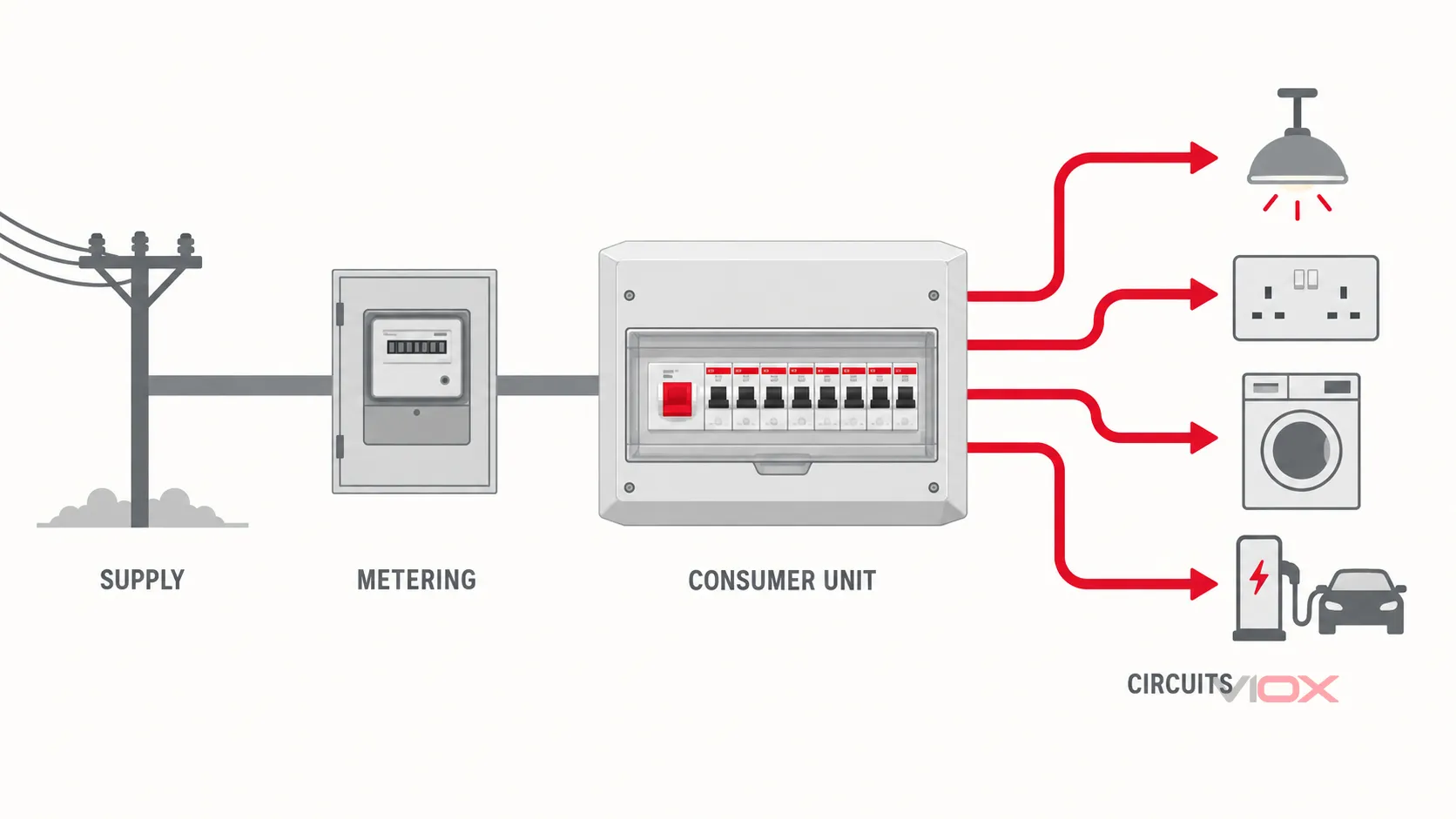
    Consumer unit system position between supply and protected outgoing circuits

    For assemblies within its scope, IEC 61439-3:2024 defines specific requirements for distribution boards intended to be operated by ordinary persons. National product standards and installation rules may add or modify requirements, so a generic consumer-unit label does not prove suitability for a particular country or project.

    Main Consumer Unit Components

    Component Primary function Important boundary
    Enclosure and internal supports Houses and supports the assembly components Material alone does not prove assembly verification or correct thermal performance
    Main switch or incomer Provides the specified incoming switching or isolation function It is not automatically an overcurrent or residual-current protective device
    Busbar or distribution system Distributes supply to outgoing protective devices Compatibility depends on the documented assembly system, not DIN-rail fit alone
    MCB Protects an outgoing circuit against overload and short circuit within its declared conditions It does not provide residual-current protection
    RCCB/RCD Provides residual-current protection to one or more circuits It normally requires separate overcurrent protection
    RCBO Combines residual-current and overcurrent protection for one circuit Type, sensitivity, curve, current, poles and breaking capacity still require selection
    SPD Limits specified transient overvoltages within a coordinated protection design It does not replace circuit overcurrent or residual-current protection
    AFDD Detects specified arc-fault signatures under its product scope It does not replace every other protective function
    Neutral and protective-conductor terminals Provide defined termination points for circuit conductors Neutral routing must match the residual-current architecture
    Blanks, labels and barriers Close unused openings and identify circuits or functions Missing or unsuitable parts can compromise the completed assembly

    Not every consumer unit contains every component. The applicable installation rules, circuit schedule, project risk assessment, and verified assembly determine the final configuration.

    What Does a Consumer Unit Protect Against?

    The enclosure provides a location for protective and switching devices, but the installed devices determine which conditions are addressed.

    Electrical condition Device that may provide the function What must still be verified
    Circuit overload MCB, RCBO, fuse, or another suitable overcurrent device Load current, conductor capacity, device characteristic, and installation rules
    Short circuit MCB, RCBO, fuse, or another suitable short-circuit device Prospective fault current, breaking capacity, disconnection time, and coordination
    Residual current RCCB/RCD or RCBO of the required type and sensitivity Waveform, IΔn, earthing arrangement, leakage budget, and circuit scope
    Transient overvoltage Coordinated SPD arrangement Supply system, exposure, SPD type, backup protection, installation and local rules
    Specified arc-fault conditions AFDD where required and correctly applied Circuit type, product scope, installation requirements, and coordination
    Manual isolation Main switch or other suitable switching device Which conductors are switched and whether the device is suitable for the intended function

    A consumer unit does not automatically protect against every shock, fire, overvoltage, power-quality, wiring, or equipment hazard. Earthing, bonding, conductor selection, circuit division, equipment protection, inspection, testing, and maintenance remain part of the complete installation.
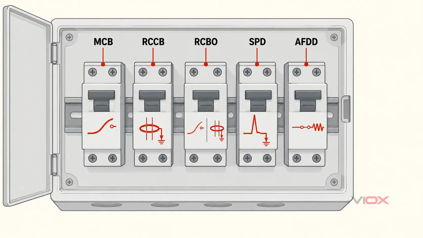
    Protection map showing MCB, RCCB, RCBO, SPD and AFDD functions inside a consumer unit

    Common Consumer Unit Architectures

    The following descriptions are orientation-level summaries. The permitted design depends on the market and project.

    Main Switch with Individual Overcurrent Devices

    In this arrangement, a main switch feeds individual MCBs or fuses. Residual-current protection may be absent, provided elsewhere, or added only to defined circuits. This architecture can be encountered in older installations or systems governed by different requirements.

    Its presence does not by itself prove that the installation is unsafe or requires immediate replacement. Condition, circuit use, earthing, test results, alterations, and current requirements determine the assessment.

    Split-Load or Dual-RCD Consumer Unit

    Circuits are divided into groups. Each group is protected by an RCCB/RCD, while individual MCBs provide overcurrent protection. A residual-current fault on one circuit can disconnect the other circuits supplied through the same RCD.

    This arrangement can be cost-effective, but circuit division, standing leakage, selectivity, neutral routing, and the consequences of losing a group of circuits require consideration.

    RCBO Consumer Unit

    Each outgoing circuit uses an individual RCBO, combining residual-current and overcurrent protection at circuit level. This normally improves fault separation because one circuit’s residual-current operation does not depend on a shared RCD protecting several unrelated circuits.

    The complete choice involves much more than fitting RCBOs. The incomer, ways, SPD, optional AFDDs, fault rating, thermal limits, busbar, terminals, approvals, circuit schedule, and documentation must form a verified assembly. Use the dedicated RCBO consumer unit selection guide for the board-level workflow.

    Mixed or High-Integrity Arrangements

    Some boards combine shared RCD groups, individual RCBOs, main-switch ways, SPDs, AFDDs, or special-purpose devices. A mixed arrangement can serve a defined circuit-division strategy, but the configuration should be read from its actual schedule and diagrams rather than inferred from a marketing label.

    Ratings and Markings to Recognize

    Before evaluating a consumer unit, distinguish these fields:

    • rated voltage and frequency: the supply conditions for which the assembly and devices are declared;
    • rated current: the current capability of the incomer, assembly, busbar, terminals, and protective devices under their respective conditions;
    • number of ways and modules: circuit positions and physical device space, which are not necessarily the same;
    • short-circuit rating: the declared fault-current capability of devices or the complete assembly under stated conditions;
    • RCBO/RCD sensitivity IΔn: the rated residual operating current;
    • residual-current type: AC, A, F, or B waveform capability where applicable;
    • trip curve: the overcurrent characteristic, such as B, C, or D for relevant devices;
    • pole and neutral arrangement: conductors monitored, protected, switched, and terminated;
    • IP rating and environmental limits: enclosure protection and permitted installation conditions; and
    • standards and approvals: the product, assembly, national, and project documents that apply.

    Do not treat a 100 A main switch, 30 mA RCBO, 10 kA breaker, and 12-way enclosure as interchangeable ratings. Each describes a different part of the design.

    When Does a Consumer Unit Need Professional Assessment?

    Arrange an assessment when there is visible damage, overheating, burning odor, water ingress, missing covers, exposed accessible parts, repeated unexplained tripping, inadequate labels, known alterations, insufficient capacity for proposed work, or uncertainty about residual-current protection.

    Age, a plastic enclosure, or the presence of rewireable fuses does not by itself establish the complete condition of the installation. An inspection and appropriate testing are needed before deciding whether to retain, repair, alter, or replace the board. The VIOX guide on how to tell if an old consumer unit needs upgrading separates observable warning signs from the evidence required for a replacement decision.

    Where replacement is planned, existing circuits should be assessed before the new board is selected. Electrical Safety First’s Best Practice Guides include guidance on replacing consumer units in domestic premises. In England, Approved Document P explains the building-regulation framework for electrical work in dwellings.

    Consumer Unit Knowledge Map

    Use the page that matches the task you need to complete:

    Reader question VIOX resource
    What does an RCBO do and what faults does it cover? What Is an RCBO?
    How do I specify a complete board using individual RCBOs? RCBO Consumer Unit Guide
    How do I choose the ratings for one RCBO circuit? How to Select the Right RCBO
    Should the board use individual RCBOs or a shared RCCB plus MCBs? RCBO vs RCCB Plus MCB
    Does an old board need replacement? Old Consumer Unit Assessment Guide
    What is involved in an old fuse-box-to-RCBO upgrade? Old Fuse Box to RCBO Consumer Unit
    How do 1P+N, 2P, 3P+N, and 4P RCBO arrangements differ? RCBO Wiring Diagrams

    Technical References

    For component-level procurement, review the documented VIOX RCBO range only after the circuit and assembly requirements are known. The exact protective device must match the board system, circuit schedule, destination-market approvals, and manufacturer documentation.
  • How Long Do Surge Protectors Last? Replacement Guide

    How Long Do Surge Protectors Last? Replacement Guide

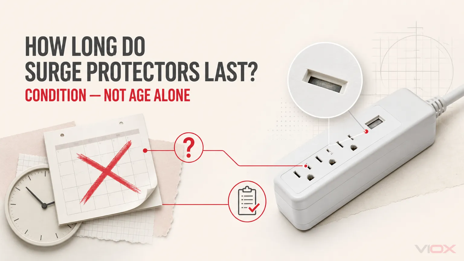
    There is no universal number of years that tells you whether a surge protector is still providing protection. A plug-in surge protector may reach end of life after one severe electrical event, accumulate damage over many smaller transients, or remain serviceable for years in a low-exposure location. Residential panel surge protective devices (SPDs) also have product-specific status and replacement instructions.
    Replace or stop using a surge protector immediately when its model-specific protection indicator shows that protection has been lost, an end-of-life disconnect or alarm operates, or the unit has heat damage, discoloration, melting, a burning odor, a damaged cord, cracked housing, or loose receptacles. If its age or history is unknown and it has no way to verify protection status, replacement is the lower-uncertainty choice for important equipment.

    A commonly repeated “three to five years” interval can be a planning reminder for some consumer products, but it is not a universal electrical test or guaranteed service life. The product instructions and its actual condition take priority.

    Surge Protector Replacement Decision Table

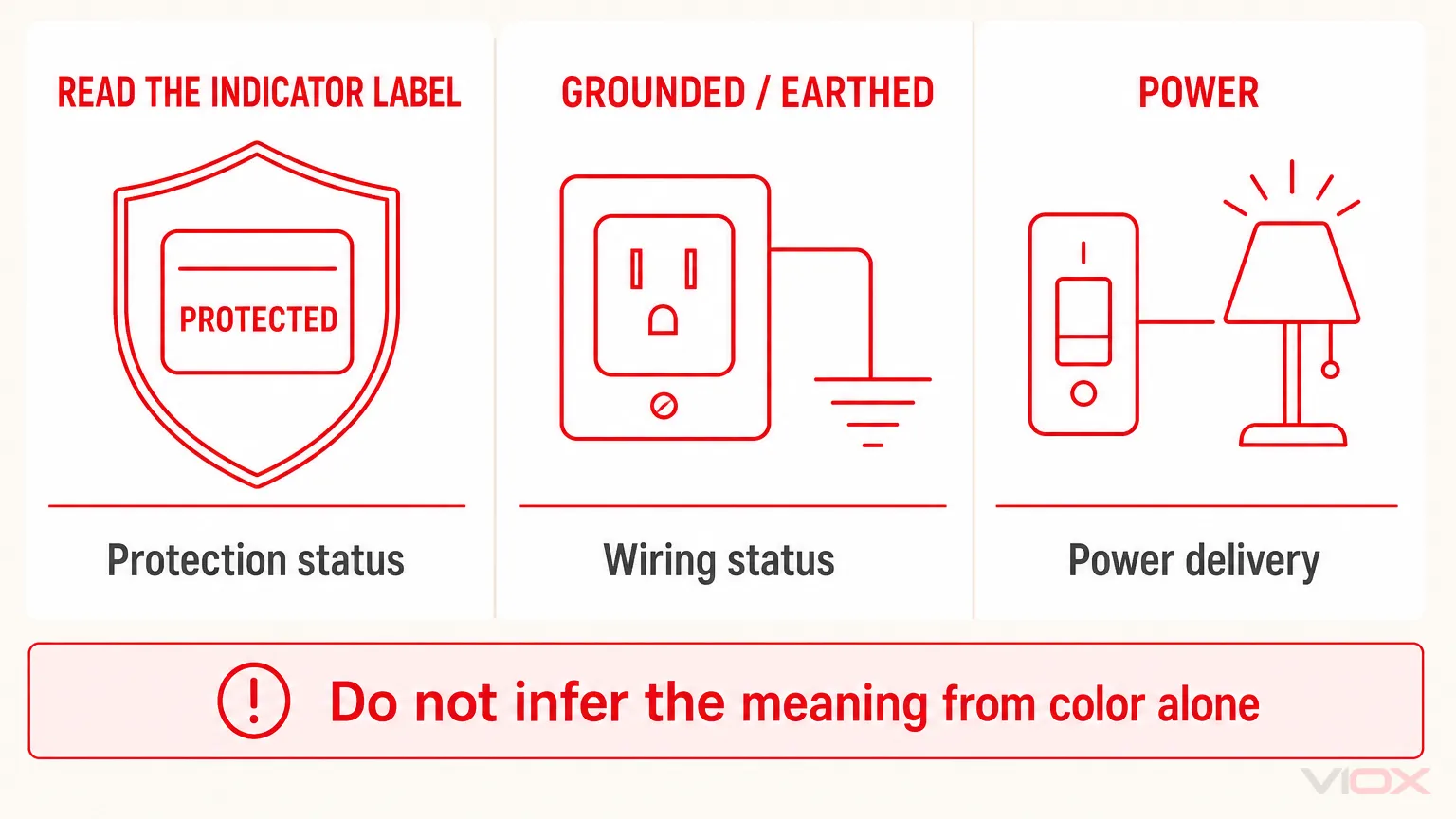
    Use the label beside the indicator—not its color alone—because indicator functions and failure behavior vary by model.

    What you observe What it may mean Recommended action
    The Protected, Protection, or equivalent model-defined status indicator is off or shows end of life The surge-protection circuit may no longer be functional, even if the outlets still have power Follow the product instructions and replace the device if the status means protection is lost
    The unit’s automatic shutoff has permanently removed outlet power A fail-safe design may have disconnected the load after the protection circuit reached end of life Unplug connected equipment and replace the surge protector; do not bypass the shutoff
    The Grounded/Earthed indicator is off or a wiring-fault indicator is on The outlet or wiring condition may be unsuitable; this is not the same as an end-of-life indication Stop relying on the device for protection and have the outlet or wiring checked by a qualified person
    The power switch or Power light is on, but the protection status is failed or unknown Power delivery does not prove that surge protection remains active Use the dedicated protection indication and model instructions; replace when protection cannot be confirmed
    The housing, plug, cord, switch, or receptacles are cracked, loose, discolored, melted, unusually hot, or producing an odor Physical or electrical damage may create a safety hazard independent of MOV condition Disconnect it safely, stop using it, and replace it
    A severe nearby lightning event, utility fault, or other major power incident occurred The protector may have experienced a stress large enough to operate its disconnect or reduce remaining capability Check status and instructions before reconnecting important equipment; replace if the manufacturer requires it or status is uncertain
    The device is old, its installation date is unknown, but it has a normal protection indication and no damage Age increases uncertainty but does not prove failure on its own Check the manual, model status function, recall information, application, and exposure history; use a conservative replacement plan for important loads
    Status is normal, the unit is undamaged, correctly applied, and within manufacturer instructions No observable end-of-life condition is present Keep it accessible, monitor its protection status, and reassess after significant events

    This framework separates three different questions: Is surge protection active? Is the wiring suitable? Is the device physically safe? One indicator or one calendar date cannot answer all three.

    Why Surge Protectors Do Not Have One Fixed Lifespan

    Many plug-in protectors and panel SPDs use metal-oxide varistors (MOVs) as voltage-limiting elements. During normal voltage, an MOV presents high impedance. During a transient overvoltage, it conducts surge current and helps limit the voltage applied to downstream equipment. For a fuller operating explanation, see how a surge protective device works.

    MOV characteristics can change as the component is exposed to surge energy and other electrical stress. One large event may be more consequential than years of low-exposure service, while repeated smaller events can create cumulative degradation. Product design may include thermal disconnection, alarms, replaceable modules, redundant protective elements, or fail-safe outlet disconnection, so end-of-life behavior is not identical across products.

    Schneider Electric’s current product guidance states that real-world SPD life cannot be predicted as one number because exposure, connected loads, installation, and surge amplitude and duration vary. NIST residential guidance likewise notes that a well-designed protector can reach end of life prematurely after exceptional stress and that failure behavior depends on design.

    The practical conclusion is simple:

    Calendar age is a risk clue. Product status, physical condition, event exposure, and manufacturer instructions determine the action.

    Seven Signs a Surge Protector Should Be Replaced or Checked

    1. The protection-status indicator shows failure

    Read the exact indicator label. A Protected light is different from a Power light, Grounded/Earthed light, or wiring-fault indicator. Belkin, for example, instructs users to replace applicable models when the Protected indicator goes out, while separately treating the Grounded/Earthed indicator as a wiring-status signal. Other manufacturers and models may use different labels, colors, alarms, displays, or contact outputs.

    Do not apply a universal “green is good, red is bad” rule. Interpret the status according to that product’s manual.

    Difference between surge protector protection, grounding and power indicators

    2. The outlets stopped supplying power because an end-of-life disconnect operated

    Some surge protectors disconnect the protected outlets when their surge-protection circuit can no longer provide the intended function. This is different from an overload breaker that can be reset after excessive connected load.
    If the instructions identify the loss of output power as permanent end-of-life operation, replace the device. Do not modify it or bypass the protective disconnect.

    3. The unit still supplies power, but protection may be gone

    Some designs can continue operating as a power tap after the surge-protection circuit has been disconnected. That is why a computer, television, or router turning on normally does not prove that it remains surge protected.

    Check the dedicated protection-status function. If the product has no indicator, alarm, diagnostic output, or documented test method, there may be no practical user test for its remaining surge capability.

    4. There is heat, discoloration, melting, cracking, or a burning odor

    These are stop-use conditions, not reasons to wait for the next scheduled inspection. Safely disconnect the unit and replace it. Also check whether the connected load, receptacle, plug fit, ventilation, liquid exposure, or wiring condition contributed to the damage.

    Do not open a plug-in surge protector to inspect or replace internal MOVs unless it is specifically designed and documented as serviceable by an appropriately qualified person.

    5. The cord, plug, switch, or receptacles are damaged or loose

    A surge protector can become unsafe through ordinary physical wear even when its surge-limiting components have not reached end of life. A frayed cord, bent or damaged plug, loose switch, cracked enclosure, or receptacle that no longer retains plugs securely is sufficient reason to remove it from service.

    6. It experienced a known severe electrical event

    After a nearby lightning event, utility fault, abnormal voltage incident, or other severe disturbance, inspect the protector before trusting it with important equipment. Look for an end-of-life indication, alarm, automatic disconnect, physical damage, or manufacturer instruction requiring replacement.

    An outage by itself is not proof that the protector absorbed a damaging surge. The relevant issue is the electrical disturbance associated with the event and the product’s resulting condition.

    7. Its age and history are unknown

    An old date does not automatically prove failure, but an unknown date, unknown surge history, missing manual, and absent status indication combine into high uncertainty. For a low-cost protector serving valuable electronics, replacement may be more defensible than assuming unused capacity remains.

    Record the installation date and model of the replacement. This makes future recall checks, warranty questions, and condition reviews easier.

    Does the Three-to-Five-Year Rule Still Matter?

    It matters as a planning convention, not as a universal pass/fail threshold.

    Some consumer and audiovisual guidance recommends periodic replacement in the three-to-five-year range. Other manufacturer guidance avoids stating a fixed life because surge exposure is unpredictable. A device can fail earlier after severe stress, while another may retain a normal status longer. Neither observation allows you to calculate its remaining protective capacity from age alone.

    Use a calendar interval when:

    • the manufacturer specifies one;
    • the device has no reliable protection-status indication;
    • the application is important enough to justify conservative preventive replacement;
    • the exposure history is uncertain;
    • a site maintenance policy establishes a reviewed interval for that equipment.

    Do not let an age rule override an active failure indication or visible damage. A one-year-old damaged protector should be replaced; a device beyond an arbitrary anniversary still requires interpretation according to its design and instructions.

    What Shortens Surge Protector Life?

    Surge severity and frequency

    The number of events alone is not enough. Waveform, amplitude, duration, source impedance, protection mode, and the energy handled by the device all affect stress. Two houses in the same neighborhood can expose their protectors to different conditions because their services, wiring, loads, and incoming paths differ.

    Sustained abnormal voltage

    An SPD is designed to limit transient overvoltage, not regulate a supply that remains too high or too low. Sustained abnormal voltage, a lost-neutral condition, or another power-system fault can stress a protector differently from a short surge and may operate its thermal protection. If lights brighten and dim abnormally, voltage remains outside its expected range, or repeated protector failures occur, diagnose the supply condition rather than repeatedly installing new power strips. See voltage protector vs surge protector for this boundary.

    Temperature, moisture, contamination, and ventilation

    Use the device only within its marked environment and instructions. Heat sources, blocked ventilation, liquid exposure, dust, corrosion, and unsuitable enclosures can affect the complete assembly, connections, and protective components.

    Product design and application fit

    Voltage compatibility, protection modes, protective-component arrangement, thermal disconnection, status indication, load rating, enclosure, and certification for the intended market all matter. A larger marketing number does not by itself prove a predictable number of service years.

    Installation and system conditions

    For panel-mounted SPDs, conductor routing, bonding, system configuration, available fault current, backup or overcurrent protection where required, and manufacturer instructions affect performance and safety. These products should be assessed and serviced by a qualified person under the applicable local rules.

    Why Joule Rating Cannot Predict Years of Life

    A plug-in protector’s joule rating is not a countdown clock. It is tied to a defined test or product declaration; it does not tell you the exact number, waveform, or severity of future surges, the current division among protective paths, the effect of sustained abnormal voltage, or the product’s end-of-life behavior.

    A higher declared energy rating may be one useful comparison input among genuinely comparable products, but “twice the joules equals twice the years” is not a valid conversion. The surge protector joule rating guide explains what that number can and cannot tell you.

    Plug-In Protector vs Panel SPD: Different Replacement Decisions

    Device What the user can check Typical next action when protection is lost
    Plug-in surge protector or surge-protected power strip Protection indicator, power behavior, grounded/wiring indicator, cord, plug, switch, receptacles, enclosure, model instructions, and recall status Safely disconnect connected equipment and replace the complete unit unless the manufacturer provides an authorized service method
    Direct plug-in or receptacle-integrated protector Model-specific status indication, physical condition, outlet fit, and instructions Follow the product instructions; fixed receptacle work may require a qualified person
    Residential panel SPD Module or device status window, alarm, display, remote contact where provided, event history, and manufacturer documentation Have a qualified person verify the system and replace the module or complete SPD exactly as the product design and instructions require

    A whole-house or panel SPD and a plug-in protector are not interchangeable lifespan categories. They protect different system locations and use different rating frameworks and maintenance methods. See whole-house vs plug-in surge protection before deciding which layer needs replacement.

    Detailed industrial SPD degradation, MOV leakage, thermal-disconnector behavior, and modular maintenance belong in the separate SPD lifespan and MOV aging guide.

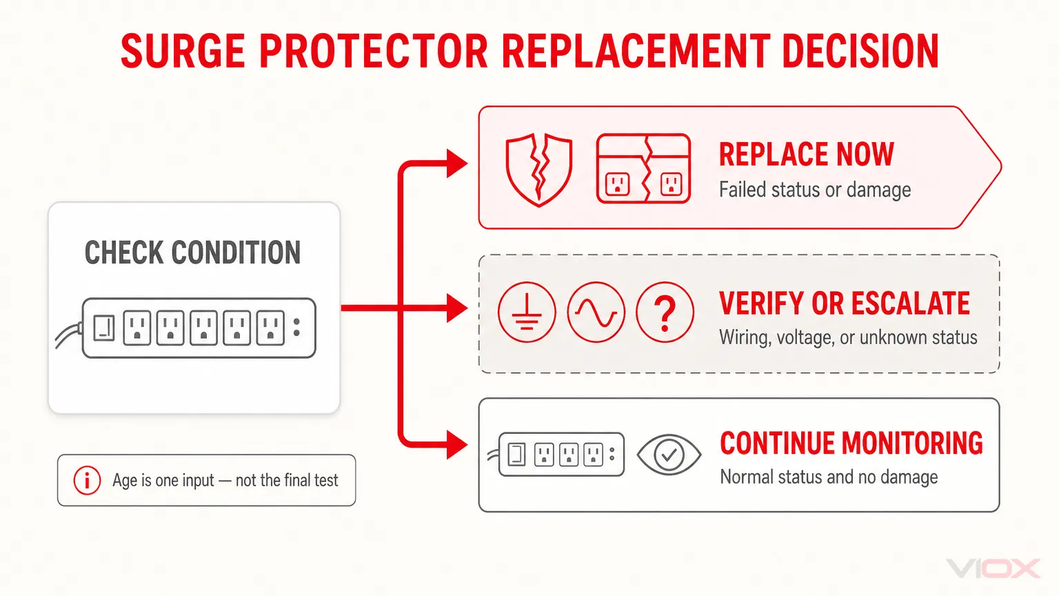
    Five-Step Condition Check

    Step 1: Identify the device and instructions

    Record the manufacturer, model, supply voltage, installation date if known, and the meaning of every indicator. Check the manufacturer’s current support page and any applicable product-recall database.

    Step 2: Read the protection status—not just the power status

    Confirm which light, alarm, display, or contact specifically represents surge-protection health. If the status means protection is unavailable, replace or service the device as instructed.

    Step 3: Inspect without opening the device

    Look for heat damage, discoloration, cracking, loose parts, damaged cords or plugs, liquid exposure, corrosion, or receptacles that do not retain plugs securely. Remove damaged equipment from service.

    Step 4: Review the exposure and application

    Consider known severe electrical events, repeated power-quality problems, environmental conditions, load use, and whether the product is suitable for the supply and connected equipment. Do not use a surge-protected strip as a substitute for a correctly rated distribution method.

    Step 5: Choose one action

    • Replace now: failed protection status, permanent end-of-life shutdown, physical damage, overheating, odor, recall requiring action, or manufacturer-mandated replacement.
    • Verify or escalate: wiring/ground fault indication, repeated failures, abnormal sustained voltage, uncertain panel-SPD status, or an installation requiring electrical work.
    • Continue monitoring: normal model-defined protection status, no damage, correct application, and no instruction requiring replacement.
    Surge protector replacement decision flow for replace, verify or continue monitoring

    Choosing a Replacement That Is Easier to Monitor

    When replacement is necessary, prioritize verifiable application fit rather than a single large marketing number:

    • correct supply voltage, plug/receptacle system, and load rating;
    • certification or listing required in the intended market;
    • a clearly labeled protection-status indicator;
    • documented end-of-life behavior, such as an alarm or automatic outlet disconnect where appropriate;
    • manufacturer instructions that explain indicator meanings and replacement action;
    • suitable protection for every connected interface that matters, including coaxial or data paths where applicable;
    • a form factor that remains visible and accessible for inspection;
    • model and purchase records that support recall and warranty checks.

    A plain power strip may provide only additional outlets and overload protection. Confirm the product is actually identified as a surge protector; see surge protector vs power strip if the distinction is unclear.

    Frequently Asked Questions

    Can a surge protector still work after its protection has failed?

    Yes. Some products continue supplying power after the surge-protection circuit is no longer active, while fail-safe designs may disconnect outlet power. Check the dedicated protection indicator and the model instructions; powered equipment alone does not prove protection.

    Should I replace a surge protector after every lightning storm?

    Not automatically after every distant storm. Check its protection status, physical condition, alarm or disconnect behavior, and manufacturer instructions after a known severe event. Replace it when protection is lost, damage is present, or the instructions require replacement.

    Can I test the remaining surge capacity with a multimeter?

    A normal user multimeter check does not establish the remaining surge-handling capability of a complete plug-in protector. Use the product’s documented diagnostics or replace it when status cannot be verified and the application justifies a conservative decision.

    Does unplugging a surge protector extend its life?

    While unplugged, it is not exposed to surges arriving through that power connection. Unplugging does not reverse previous degradation or repair physical wear, and connected equipment may still have other conductive paths such as coaxial or data cables.

    Is the surge protection inside a UPS permanent?

    No assumption should be made from the UPS operating normally. Battery condition, power-conversion functions, and the surge-protection stage are separate. Follow the UPS manufacturer’s status, test, maintenance, and replacement instructions.

    How should an old surge protector be disposed of?

    Follow the manufacturer’s guidance and local electronic-waste or electrical-equipment disposal rules. Do not place a damaged or overheated unit back into service while waiting for disposal.

    Final Replacement Rule

    Do not replace a surge protector solely because an internet table says it reached a universal birthday, and do not keep it solely because its outlets still work.

    Replace it when its model-defined protection status is failed, its end-of-life disconnect operates, it is physically damaged, or the manufacturer requires replacement. Verify or escalate wiring faults, abnormal voltage, repeated failures, and panel-SPD service. When status is normal and the device remains suitable and undamaged, continue monitoring it according to its instructions.

    For residential protection planning beyond one device, combine this condition-based decision with the correct protection locations. Review the VIOX SPD product family when evaluating panel-mounted options, and request model-specific ratings and documentation for the intended electrical system and market.

    Sources Reviewed

  • DC Fuse Breaking Capacity for PV Systems

    DC Fuse Breaking Capacity for PV Systems

    Breaking capacity for DC fuses in PV systems is the maximum fault current a fuse can safely interrupt without causing damage or creating safety hazards. For photovoltaic installations, this typically ranges from 600A to 30,000A depending on system size and design, with most residential systems requiring fuses rated between 1,000A to 10,000A breaking capacity.

    Understanding DC fuse breaking capacity is critical for solar system safety, code compliance, and preventing catastrophic failures that can lead to fires, equipment damage, or personal injury. Unlike AC systems, DC circuits present unique challenges that make proper fuse selection essential for reliable protection.

    What is Breaking Capacity in DC Fuses?

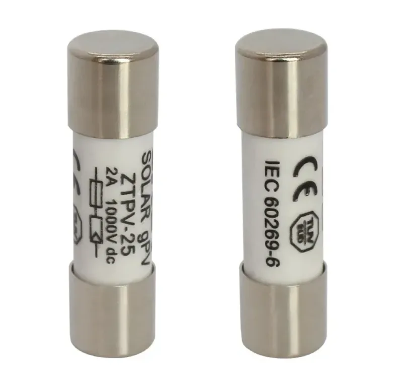
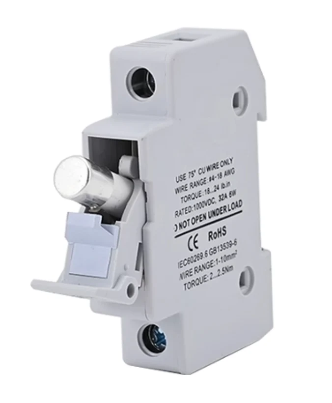
    two DC fuse

    Breaking capacity (also called interrupting capacity or fault current rating) represents the maximum current a DC fuse can safely interrupt during a fault condition without sustaining damage or creating dangerous arcing.

    Key Definitions for PV Systems

    • Breaking Capacity: The maximum short-circuit current a fuse can interrupt safely, measured in amperes (A) or kiloamperes (kA).
    • DC Fault Current: Abnormal current flow in photovoltaic circuits caused by equipment failure, wiring problems, or ground faults.
    • Prospective Short-Circuit Current: The theoretical maximum current that could flow in a circuit during a fault condition, calculated based on system design parameters.
    • Time-Current Characteristic: The relationship between fault current magnitude and the time required for the fuse to operate.

    DC vs AC Fuse Breaking Capacity: Critical Differences

    Aspect DC Fuses AC Fuses
    Arc Extinction No natural current zero crossing Natural zero crossing every half cycle
    Breaking Capacity Typically 600A to 30,000A Often higher due to easier arc extinction
    Voltage Rating Must handle continuous DC voltage Benefits from AC voltage reversals
    Arc Duration Longer, more sustained arcs Shorter arcs due to zero crossings
    Physical Size Often larger for same current rating More compact design possible
    Cost Generally higher due to design complexity Lower cost for equivalent ratings
    Standards IEC 60269-6, UL 2579 IEC 60269-1, UL 248

    Expert Tip: Why DC Breaking Capacity Matters More

    DC circuits create sustained arcs because there’s no natural current zero crossing to help extinguish the arc. This makes adequate breaking capacity absolutely critical for safety – never compromise on this specification.

    Breaking Capacity Requirements for Different PV System Types

    dc fuse breaking capacity for PV

    Residential Solar Systems (2-20kW)

    System Size Typical Breaking Capacity Common Applications
    2-5kW 1,000A – 3,000A Small residential rooftops
    5-10kW 3,000A – 6,000A Medium residential installations
    10-20kW 6,000A – 10,000A Large residential or small commercial

    Commercial Solar Systems (20kW-1MW)

    System Size Typical Breaking Capacity Design Considerations
    20-100kW 10,000A – 15,000A Multiple combiner boxes
    100-500kW 15,000A – 25,000A Central inverter designs
    500kW-1MW 25,000A – 30,000A Utility-scale installations

    Utility-Scale Systems (1MW+)

    Breaking Capacity Range: 30,000A and higher
    Special Requirements: Custom engineered solutions with enhanced arc flash protection

    How to Calculate Required Breaking Capacity

    Step 1: Determine Maximum Short-Circuit Current

    Calculate based on the worst-case scenario:

    1. Module Short-Circuit Current (Isc): Use manufacturer specifications
    2. Array Configuration: Consider parallel string connections
    3. Temperature Derating: Account for cold weather increases
    4. Safety Factor: Apply 1.25x multiplier per NEC requirements

    Step 2: Calculate Prospective Fault Current

    Formula for PV array fault current:

    Maximum Fault Current = (Number of Parallel Strings × Module Isc × 1.25 × Temperature Factor)

    Step 3: Select Fuse Breaking Capacity

    Breaking capacity must exceed calculated fault current by minimum 20% safety margin.

    Calculated Fault Current Minimum Breaking Capacity Required
    500A 1,000A (600A minimum)
    1,500A 3,000A
    5,000A 10,000A
    15,000A 20,000A
    25,000A 30,000A

    Safety Warning: Critical Breaking Capacity Considerations

    ⚠️ DANGER: Installing fuses with inadequate breaking capacity can result in:

    • Catastrophic failure during fault conditions
    • Fire hazards from sustained arcing
    • Equipment damage throughout the system
    • Personal injury from arc flash incidents
    • Code violations and failed inspections

    Standards and Code Requirements

    National Electrical Code (NEC) Requirements

    Article 690.9(C): Overcurrent devices must be rated for the maximum available fault current at their installation point.

    Article 690.9(D): DC circuits require specific breaking capacity calculations based on system configuration.

    International Standards Compliance

    Standard Application Key Requirements
    IEC 60269-6 DC fuses for PV applications Breaking capacity testing methods
    UL 2579 DC fuses for PV systems Safety and performance standards
    IEC 61730 PV module safety qualification System-level protection requirements
    UL 1741 Inverter safety standard Grid-tie protection coordination

    Selection Criteria for DC Fuse Breaking Capacity

    Primary Selection Factors

    1. System Fault Current Analysis
      • Calculate maximum prospective short-circuit current
      • Include temperature variations and aging factors
      • Consider future system expansions
    2. Installation Environment
      • Ambient temperature effects on performance
      • Altitude derating requirements
      • Moisture and contamination exposure
    3. Coordination Requirements
      • Upstream and downstream protection devices
      • Selective coordination for system reliability
      • Arc flash hazard reduction

    Expert Selection Guidelines

    For Residential Systems:

    • Minimum 1,000A breaking capacity for small arrays
    • 3,000A-6,000A for typical installations
    • Consider 10,000A for future expansion capability

    For Commercial Systems:

    • 10,000A minimum for most applications
    • 20,000A for large installations
    • Custom calculations for utility-scale projects

    Common Breaking Capacity Problems and Solutions

    Problem 1: Inadequate Breaking Capacity Rating

    Symptoms:

    • Fuse fails to clear during fault
    • Sustained arcing and equipment damage
    • Safety hazards and code violations

    Solution:

    • Recalculate system fault current
    • Upgrade to higher breaking capacity fuses
    • Verify installation meets current codes

    Problem 2: Over-Specified Breaking Capacity

    Symptoms:

    • Unnecessarily high costs
    • Oversized equipment requirements
    • Complex installation procedures

    Solution:

    • Optimize calculations for actual system needs
    • Balance safety margins with practical requirements
    • Consider standardization across installations

    Professional Installation and Maintenance

    Installation Best Practices

    1. Verify Calculations: Always confirm breaking capacity requirements before installation
    2. Use Certified Components: Ensure fuses meet UL 2579 or equivalent standards
    3. Follow Manufacturer Guidelines: Adhere to specific installation requirements
    4. Document Specifications: Maintain records for inspection and maintenance

    Maintenance Requirements

    Annual Inspections:

    • Visual inspection for signs of thermal stress
    • Verification of proper torque specifications
    • Testing of protection coordination

    Replacement Indicators:

    • Physical damage or discoloration
    • Blown fuses indicating system problems
    • Upgraded system components requiring higher ratings

    Quick Reference: Breaking Capacity Selection Chart

    PV System Type System Size Recommended Breaking Capacity Safety Notes
    Residential Small 2-5kW 1,000A – 3,000A Minimum code compliance
    Residential Medium 5-10kW 3,000A – 6,000A Standard residential protection
    Residential Large 10-20kW 6,000A – 10,000A Enhanced protection recommended
    Commercial Small 20-100kW 10,000A – 15,000A Engineering analysis required
    Commercial Large 100kW-1MW 15,000A – 30,000A Professional design mandatory
    Utility Scale 1MW+ 30,000A+ Custom engineering required

    Frequently Asked Questions

    What happens if I use a fuse with insufficient breaking capacity?

    If the breaking capacity is too low, the fuse may not be able to safely interrupt fault currents, potentially causing sustained arcing, equipment damage, fire hazards, and safety risks. The fuse could fail catastrophically during a fault condition.

    How do I know what breaking capacity my PV system needs?

    Calculate the maximum prospective short-circuit current based on your array configuration, module specifications, and environmental factors. The breaking capacity must exceed this calculated value with appropriate safety margins (typically 20% minimum).

    Can I use AC fuses in DC applications?

    No, AC fuses should never be used in DC applications. DC circuits require special fuse designs because they don’t have natural current zero crossings to help extinguish arcs. Always use fuses specifically rated for DC applications.

    How does temperature affect breaking capacity requirements?

    Cold temperatures increase the short-circuit current capability of PV modules, potentially requiring higher breaking capacity fuses. Hot temperatures can reduce fuse performance. Always consider temperature variations in your calculations.

    What’s the difference between breaking capacity and current rating?

    Current rating is the continuous current the fuse can carry without operating. Breaking capacity is the maximum fault current the fuse can safely interrupt. Both specifications are critical but serve different protection functions.

    Do I need different breaking capacities for string and combiner fuses?

    Yes, string fuses typically need lower breaking capacity (1,000A-3,000A) since they protect individual strings. Combiner fuses need higher breaking capacity (3,000A-20,000A+) because they see fault currents from multiple parallel strings.

    How often should breaking capacity requirements be reviewed?

    Review breaking capacity requirements whenever you modify the system (add modules, change configuration) or when codes are updated. Also review during major maintenance periods or after any protective device operations.

    What standards govern breaking capacity for PV fuses?

    Primary standards include UL 2579 for DC fuses in PV applications, IEC 60269-6 for international applications, and NEC Article 690 for installation requirements. Always verify current code requirements for your jurisdiction.

    Expert Recommendations and Next Steps

    For System Designers: Always perform detailed fault current analysis and select fuses with adequate safety margins. Consider future system expansion in your calculations.

    For Installers: Verify breaking capacity specifications before installation and maintain detailed documentation for inspections and maintenance.

    For System Owners: Work with qualified professionals to ensure your system meets current safety standards and code requirements.

    Professional Consultation Recommended: For systems over 100kW or complex installations, consult with electrical engineers specializing in PV systems to ensure optimal protection design.

    Understanding and properly applying DC fuse breaking capacity requirements is essential for safe, reliable, and code-compliant photovoltaic installations. When in doubt, always consult with certified professionals and err on the side of higher safety margins.

    Related

    How to Test a Bad DC Fuse in PV System

    Fuse Electrical Symbols: Complete Guide to Standards, Types & Applications

    How to Properly Fuse a Solar Photovoltaic System

    How Does a Fuse Holder Work?

  • LCU vs LCS Circuit Breaker Ratings: Complete Technical Guide for Electrical Engineers

    LCU vs LCS Circuit Breaker Ratings: Complete Technical Guide for Electrical Engineers

    Direct Answer: LCU (Limiting Current Under short circuit) and LCS (Limiting Current under Service conditions) are two critical circuit breaker ratings that define maximum current interruption capabilities. LCU measures the highest short-circuit current a breaker can safely interrupt under fault conditions, while LCS indicates the maximum current during normal service operations. Understanding these ratings is essential for proper circuit breaker selection and electrical system safety.

    VIOX VRO6-63 4P Electronic Type 6-63A Residual Current Circuit Breaker with Overload Protection

    What Are LCU and LCS Circuit Breaker Ratings?

    LCU (Limiting Current Under short circuit conditions) represents the maximum prospective short-circuit current that a circuit breaker can interrupt safely. This rating ensures the breaker can handle the most severe fault conditions without catastrophic failure.

    LCS (Limiting Current under Service conditions) defines the maximum current the circuit breaker can handle during normal operational use, including planned load switching and minor overload conditions.

    Key Differences Between LCU and LCS Ratings

    Here is a table that shows the fundamental differences between LCU and LCS circuit breaker ratings:

    Characteristic LCU (Limiting Current Under short circuit) LCS (Limiting Current under Service)
    Primary Purpose Short-circuit fault protection Normal operational current handling
    Current Type Maximum fault current interruption Maximum service current interruption
    Frequency of Use Emergency fault conditions only Regular operational switching
    Testing Standard IEC 60947-2, UL 489 IEC 60947-2, UL 489
    Typical Values 10kA to 200kA+ 1kA to 100kA
    Safety Factor Critical for system protection Important for operational reliability
    Cost Impact Higher LCU = higher cost Higher LCS = moderate cost increase

    Technical Specifications and Standards Compliance

    LCU Rating Classifications

    ⚠️ Safety Warning: Always verify LCU ratings exceed calculated fault currents by at least 25% safety margin per NEC 110.9.

    Circuit breakers are classified by LCU ratings according to these industry standards:

    • Low LCU (5-15kA): Residential and light commercial applications
    • Medium LCU (25-65kA): Commercial and light industrial systems
    • High LCU (100kA+): Heavy industrial and utility applications

    LCS Rating Categories

    LCS ratings typically follow these classifications:

    • Standard LCS (25-50kA): General commercial use
    • Enhanced LCS (65-100kA): Industrial applications with frequent switching
    • Premium LCS (100kA+): Critical infrastructure and heavy industry

    Real-World Applications and Use Cases

    When LCU Rating Is Critical

    • Power Distribution Systems: In electrical panels serving large commercial buildings, LCU ratings of 65kA or higher ensure protection against utility-level fault currents.
    • Industrial Motor Control Centers: Manufacturing facilities require circuit breakers with LCU ratings matching or exceeding calculated short-circuit currents at the point of installation.
    • Emergency Generator Systems: Backup power systems need appropriate LCU ratings to handle generator fault contributions safely.

    When LCS Rating Matters Most

    • Frequent Load Switching: Operations requiring regular motor starting, lighting control, or equipment cycling benefit from higher LCS ratings.
    • Variable Load Applications: Systems with changing power demands, such as data centers or manufacturing lines, require adequate LCS capacity.
    • Maintenance Operations: Facilities requiring regular electrical maintenance need circuit breakers with sufficient LCS ratings for safe isolation procedures.

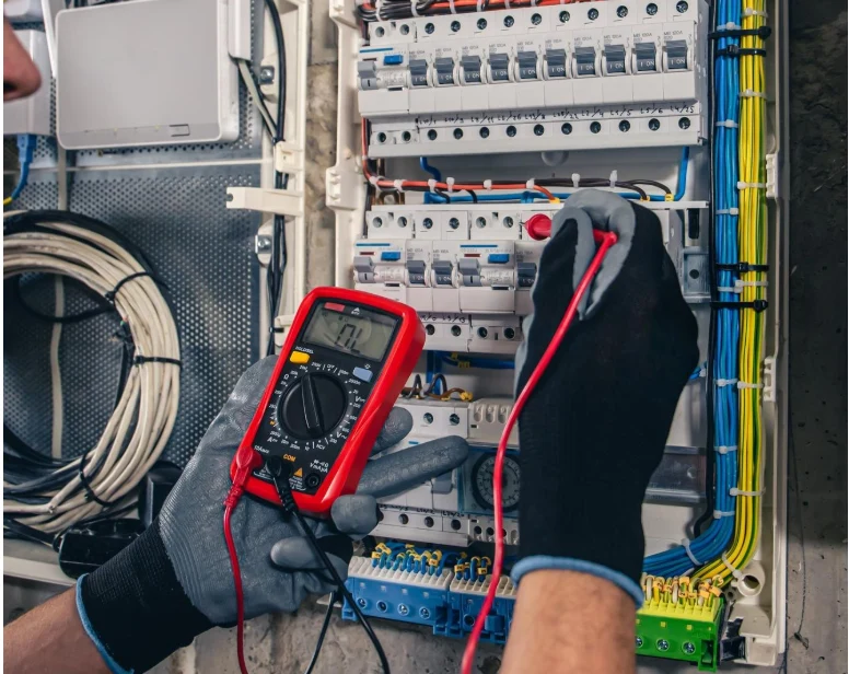
    man testing mcb

    How to Choose Between Different LCU and LCS Ratings

    Expert Tip: Calculate Required Ratings First

    Before selecting circuit breakers, perform these essential calculations:

    1. Short-Circuit Analysis: Calculate maximum available fault current at each breaker location
    2. Load Analysis: Determine maximum operational currents including starting currents
    3. Safety Factor Application: Add 25% minimum safety margin to calculated values

    Selection Criteria Framework

    Step 1: Determine Required LCU Rating

    • Calculate short-circuit current at installation point
    • Include utility contribution and local generation
    • Add safety factor per NEC 110.9 requirements
    • Select breaker with LCU ≥ calculated fault current

    Step 2: Evaluate LCS Requirements

    • Assess normal operational current levels
    • Consider motor starting currents and inrush
    • Account for future load growth (typically 25%)
    • Select appropriate LCS rating for application

    Step 3: Verify Code Compliance

    • Confirm ratings meet NEC, IEC, or local code requirements
    • Check coordination with upstream protective devices
    • Validate with electrical engineer or certified professional

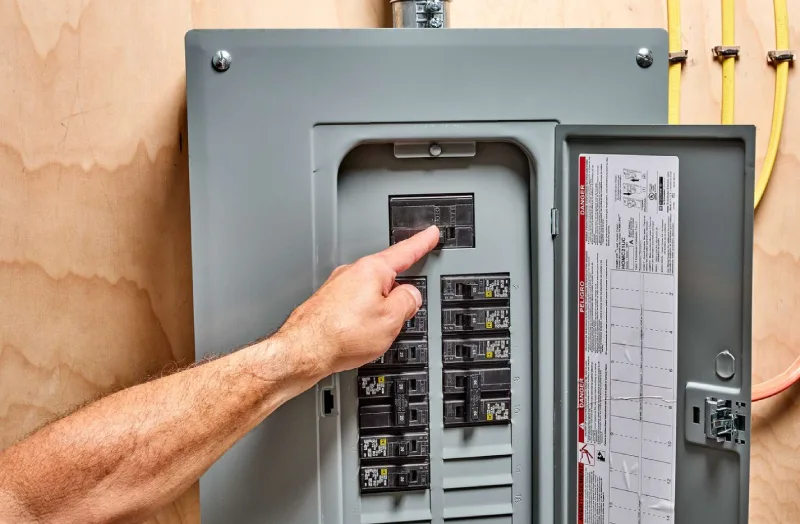
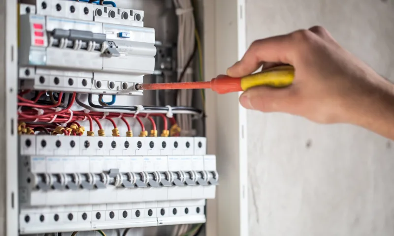
    A hand operating a residential electrical circuit breaker panel showing multiple miniature circuit breakers (MCBs) used to protect circuits from overloads and short circuits

    Common Selection Mistakes and Troubleshooting

    Safety Warning: Improper Rating Selection Risks

    Installing circuit breakers with inadequate LCU or LCS ratings can result in:

    • Equipment damage during fault conditions
    • Fire hazards from arc flash incidents
    • Electrical system instability
    • Code violations and inspection failures

    Troubleshooting Rating Issues

    Problem: Circuit breaker trips frequently during normal operation

    Solution: Check if LCS rating is adequate for actual load conditions, including starting currents

    Problem: Breaker fails to interrupt fault current properly

    Solution: Verify LCU rating exceeds calculated short-circuit current at installation point

    Problem: Coordination issues with upstream devices

    Solution: Ensure proper selectivity between LCU/LCS ratings throughout the electrical system

    Professional Installation and Safety Requirements

    Code Compliance Requirements

    National Electrical Code (NEC) 110.9: Circuit breakers must have interrupting ratings sufficient for the available fault current.

    IEC 60947-2 Standard: International standard defining test procedures and performance requirements for LCU and LCS ratings.

    UL 489 Certification: Underwriters Laboratories standard ensuring circuit breaker performance meets safety requirements.

    Expert Tip: Professional Verification Required

    Always have qualified electrical engineers verify:

    • Short-circuit calculations and studies
    • Circuit breaker coordination analysis
    • Code compliance and inspection readiness
    • Safety factor adequacy for specific applications

    Quick Reference: LCU vs LCS Selection Guide

    For Residential Applications

    • LCU Rating: 10-15kA typically sufficient
    • LCS Rating: Based on panel amperage and load requirements
    • Key Consideration: Utility fault current availability

    For Commercial Buildings

    • LCU Rating: 25-65kA depending on service size
    • LCS Rating: Match operational switching requirements
    • Key Consideration: Future expansion and load growth

    For Industrial Facilities

    • LCU Rating: 65kA+ for motor control centers
    • LCS Rating: Enhanced ratings for frequent switching
    • Key Consideration: Motor starting and arc flash analysis

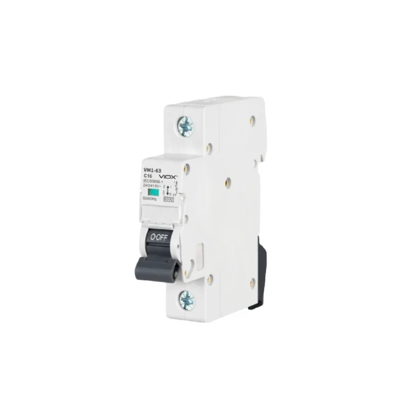
    MCB without logo IN BOX

    Frequently Asked Questions

    What happens if I use a circuit breaker with insufficient LCU rating?
    Using a breaker with inadequate LCU rating creates serious safety hazards. During fault conditions, the breaker may fail to interrupt the current properly, leading to equipment damage, fire, or arc flash incidents.

    How do I calculate the required LCU rating for my application?
    Perform a short-circuit study to determine maximum available fault current at each breaker location. This requires calculating utility contribution, transformer impedance, and conductor impedance to the point of installation.

    Can I use a circuit breaker with higher LCU or LCS ratings than required?
    Yes, using breakers with higher ratings than minimum requirements provides additional safety margin. However, this typically increases cost, so balance safety requirements with budget considerations.

    What is the difference between LCU and breaking capacity?
    LCU (Limiting Current Under short circuit) and breaking capacity both relate to fault current interruption, but LCU specifically refers to the maximum current under short-circuit conditions, while breaking capacity may include other operational parameters.

    Do LCU and LCS ratings affect circuit breaker coordination?
    Yes, proper coordination requires matching LCU and LCS ratings throughout the electrical system to ensure selective operation during fault and overload conditions.

    How often should LCU and LCS ratings be verified?
    Verify ratings during initial installation, system modifications, load additions, or utility service changes. Periodic review every 5 years ensures continued adequacy as systems evolve.

    What safety certifications should I look for in circuit breaker ratings?
    Look for UL 489 listing, IEC 60947-2 compliance, and CSA certification. These ensure the stated LCU and LCS ratings have been independently verified through proper testing procedures.

    Are there special considerations for LCU and LCS in renewable energy systems?
    Yes, solar and wind systems can contribute to fault currents, affecting required LCU ratings. Additionally, inverter-based systems may require special consideration for LCS ratings due to switching characteristics.

    Conclusion and Expert Recommendations

    Understanding LCU and LCS circuit breaker ratings is fundamental to electrical system safety and reliability. LCU ratings protect against catastrophic fault conditions, while LCS ratings ensure proper operation during normal service.

    Key takeaways for proper selection:

    • Always calculate actual system requirements before selecting ratings
    • Apply appropriate safety factors per applicable electrical codes
    • Consider future load growth and system modifications
    • Verify compliance with NEC, IEC, and local code requirements
    • Engage qualified electrical professionals for complex applications

    ⚠️ Final Safety Reminder: Circuit breaker selection significantly impacts electrical system safety. When in doubt, consult with licensed electrical engineers or certified electricians to ensure proper rating selection and code compliance.

    Related

    What Is a Miniature Circuit Breaker (MCB): Complete Guide for Safety and Selection

    IEC 60898-1 vs IEC 60947-2: Complete Guide to Electrical Circuit Breaker Standards

    Why Circuit Breakers DON’T Protect People: The Critical Safety Truth Every Homeowner Must Know

  • Mechanical Life vs Electrical Life of Circuit Breakers

    Mechanical Life vs Electrical Life of Circuit Breakers

    Direct Answer: The mechanical life of a circuit breaker refers to the total number of open/close operations it can perform under no-load conditions, while electrical life refers to the number of operations it can perform while interrupting actual electrical current. Mechanical life is typically 10-50 times longer than electrical life, with mechanical operations ranging from 10,000-30,000 cycles compared to electrical operations of 100-3,000 cycles.

    Understanding these differences is crucial for proper circuit breaker selection, maintenance scheduling, and ensuring electrical system safety and reliability.

    install circuit breaker

    What Are Mechanical Life and Electrical Life?

    Mechanical Life Definition

    Mechanical life represents the maximum number of opening and closing operations a circuit breaker can perform when no electrical current is flowing through it. These are purely mechanical movements of the breaker’s contacts without any electrical stress or arc formation.

    Electrical Life Definition

    Electrical life indicates the maximum number of operations a circuit breaker can perform while interrupting electrical current under normal or fault conditions. Each electrical operation subjects the breaker to electrical stress, arc formation, and contact erosion.

    Key Differences Between Mechanical and Electrical Life

    Aspect Mechanical Life Electrical Life
    Definition Operations with no current flow Operations while interrupting current
    Typical Range 10,000-30,000 cycles 100-3,000 cycles
    Stress Factors Physical wear only Electrical stress + physical wear
    Arc Formation None Significant arcing occurs
    Contact Erosion Minimal Progressive degradation
    Testing Standard IEC 62271-100, IEEE C37.09 IEC 62271-100, IEEE C37.04
    Maintenance Impact Predictable wear patterns Requires electrical testing

    Operational Stress Comparison

    Stress Type Mechanical Operations Electrical Operations
    Physical Wear Springs, linkages, mechanisms All mechanical components
    Contact Degradation Surface oxidation only Arc erosion, pitting, welding
    Temperature Effects Ambient temperature only Arc temperatures (15,000°C+)
    Insulation Stress None Dielectric breakdown risk
    Gas/Oil Degradation Minimal Decomposition from arcing

    Why Electrical Life Is Significantly Shorter

    Arc Formation Impact: When a circuit breaker interrupts current, an electrical arc forms between the opening contacts. This arc:

    • Reaches temperatures exceeding 15,000°C
    • Causes contact material erosion
    • Creates metal vapor and gas decomposition
    • Generates electromagnetic forces

    Contact Erosion Process: Each electrical operation removes microscopic amounts of contact material through:

    1. Thermal erosion from arc temperature
    2. Mechanical erosion from electromagnetic forces
    3. Chemical erosion from oxidation and contamination
    4. Electrical erosion from current density effects

    ⚠️ Safety Warning: Never operate circuit breakers beyond their rated electrical life as this can lead to catastrophic failure, fire, or explosion hazards.

    Circuit Breaker Life Specifications by Type

    Low Voltage Circuit Breakers (≤1000V)

    Breaker Type Mechanical Life Electrical Life Typical Applications
    Miniature (MCB) 20,000 cycles 10,000 @ rated current Residential, light commercial
    Molded Case (MCCB) 10,000-25,000 cycles 1,000-10,000 cycles Industrial distribution
    Insulated Case (ICCB) 10,000 cycles 3,000-5,000 cycles Motor control, feeders
    Air Circuit (ACB) 10,000-30,000 cycles 1,000-8,000 cycles Main distribution

    Medium Voltage Circuit Breakers (1kV-38kV)

    Technology Mechanical Life Electrical Life Key Features
    Vacuum 10,000-30,000 cycles 100-3,000 cycles Minimal maintenance
    SF6 Gas 10,000-25,000 cycles 100-2,000 cycles High interrupting capacity
    Air Blast 10,000 cycles 500-1,500 cycles Legacy technology
    Oil 5,000-10,000 cycles 300-1,000 cycles Older installations

    High Voltage Circuit Breakers (>38kV)

    Voltage Class Mechanical Life Electrical Life Critical Considerations
    72.5kV 10,000 cycles 100-500 cycles Transmission applications
    145kV 10,000 cycles 100-300 cycles Grid interconnection
    245kV+ 5,000-10,000 cycles 50-200 cycles Critical infrastructure

    Factors Affecting Circuit Breaker Life

    Mechanical Life Factors

    • Operating mechanism type (spring, hydraulic, pneumatic)
    • Ambient temperature and humidity
    • Vibration and seismic conditions
    • Maintenance quality and frequency
    • Lubrication condition

    Electrical Life Factors

    • Fault current magnitude (higher current = shorter life)
    • Arc duration (faster opening = longer life)
    • Power factor (inductive loads more severe)
    • Recovery voltage (system voltage recovery rate)
    • Operating sequence (close-open vs. open-close-open)

    Expert Tip: Circuit breakers used in motor starting applications experience reduced electrical life due to high inrush currents, even though these aren’t technically fault conditions.

    How to Determine Circuit Breaker Life Requirements

    Step 1: Analyze Operating Conditions

    1. Calculate expected mechanical operations per year
    2. Estimate electrical operations per year
    3. Identify maximum fault current levels
    4. Determine duty cycle requirements

    Step 2: Apply Derating Factors

    Condition Derating Factor Application
    High fault current 0.5-0.8 Reduce electrical life
    Frequent switching 0.7-0.9 Reduce mechanical life
    Poor maintenance 0.6-0.8 Apply to both
    Harsh environment 0.8-0.9 Primarily mechanical
    Critical application 0.5-0.7 Conservative safety factor

    Step 3: Calculate Required Life

    Required Mechanical Life = (Annual mechanical ops × Service years) ÷ Derating factor
    Required Electrical Life = (Annual electrical ops × Service years) ÷ Derating factor
    

    Maintenance and Life Extension Strategies

    Mechanical Life Extension

    • Regular lubrication of operating mechanisms
    • Calibration of trip settings and timing
    • Inspection of springs and linkages
    • Environmental protection (heating, ventilation)
    • Vibration monitoring in critical applications

    Electrical Life Extension

    • Contact resistance monitoring to detect erosion
    • Insulation testing to verify dielectric integrity
    • Arc chamber inspection for contamination
    • Contact replacement at 70-80% of rated life
    • Gas/oil analysis for decomposition products

    ⚠️ Professional Recommendation: Electrical testing should be performed by qualified technicians using appropriate safety procedures and PPE.

    Standards and Testing Requirements

    International Standards

    • IEC 62271-100: High-voltage switchgear and controlgear
    • IEC 60947-2: Low-voltage switchgear and controlgear
    • IEEE C37.04: Rating structure for AC high-voltage circuit breakers
    • IEEE C37.09: Test procedures for AC high-voltage circuit breakers

    Testing Categories

    1. Type testing – Manufacturer verification of design
    2. Routine testing – Every manufactured unit
    3. Periodic testing – In-service verification
    4. Condition assessment – Life remaining evaluation

    Selection Criteria for Circuit Breaker Life

    When Mechanical Life Is Primary Concern

    • Load switching applications (transformers, capacitors)
    • Transfer switching systems
    • Maintenance switching operations
    • Remote control applications

    When Electrical Life Is Primary Concern

    • Fault protection applications
    • Motor starting/stopping
    • Arc furnace protection
    • Capacitor bank switching

    Decision Matrix for Life Requirements

    Application Type Priority Factor Typical Life Ratio (M:E)
    Protection only Electrical life 20:1 to 50:1
    Load switching Mechanical life 10:1 to 20:1
    Motor control Both equal 5:1 to 15:1
    Capacitor switching Electrical life 15:1 to 30:1

    Frequently Asked Questions

    What happens when a circuit breaker exceeds its electrical life?

    When electrical life is exceeded, contact erosion increases failure risk, arc interruption capability decreases, and the breaker may fail to clear faults safely, potentially causing equipment damage or fire hazards.

    Can mechanical life be converted to electrical life?

    No, these are separate ratings. Operating a breaker electrically always consumes both mechanical and electrical life, but mechanical operations only consume mechanical life.

    How do you monitor circuit breaker life in service?

    Use operation counters for mechanical operations, fault current monitoring for electrical stress, contact resistance measurements, and periodic maintenance testing per manufacturer recommendations.

    What’s the difference between rated life and actual life?

    Rated life represents laboratory test conditions. Actual life depends on operating environment, current levels, maintenance quality, and specific application stresses.

    Should you replace circuit breakers at 100% of rated life?

    Industry best practice recommends replacement or major refurbishment at 70-80% of rated electrical life to maintain reliable protection and safety margins.

    How does fault current level affect electrical life?

    Higher fault currents create more severe arcing conditions, reducing electrical life exponentially. A breaker interrupting 50% of rated current may achieve 2-3 times longer electrical life.

    Can circuit breaker life be extended through maintenance?

    Mechanical life can be significantly extended through proper maintenance. Electrical life can be partially restored through contact replacement, but the interrupting chamber has finite life.

    What documentation is required for life tracking?

    Maintain operation logs, fault current records, maintenance histories, test results, and manufacturer life curves for accurate life assessment and regulatory compliance.

    Expert Selection Guidelines

    For New Installations:

    1. Calculate expected operations over design life
    2. Apply appropriate safety factors (typically 1.5-2.0)
    3. Consider future system growth and fault levels
    4. Specify monitoring capabilities for life tracking

    For Existing Systems:

    1. Review historical operation data
    2. Assess current condition through testing
    3. Plan replacement before reaching critical life limits
    4. Consider upgrading to higher-life technologies

    ⚠️ Critical Safety Note: Circuit breaker life ratings are fundamental safety parameters. Exceeding rated life can result in failure to interrupt fault currents, leading to catastrophic equipment damage, fire, or personnel injury. Always consult qualified electrical engineers for critical applications and maintain detailed operation records for life tracking.

    Related

    IEC 60898-1 vs IEC 60947-2: Complete Guide to Electrical Circuit Breaker Standards

    GFCI vs AFCI: The Complete Guide to Electrical Safety Circuit Breakers

    How to Know If Circuit Breaker is Bad​

  • RCCB vs MCB: Key Differences and Why You Need Both

    RCCB vs MCB: Key Differences and Why You Need Both

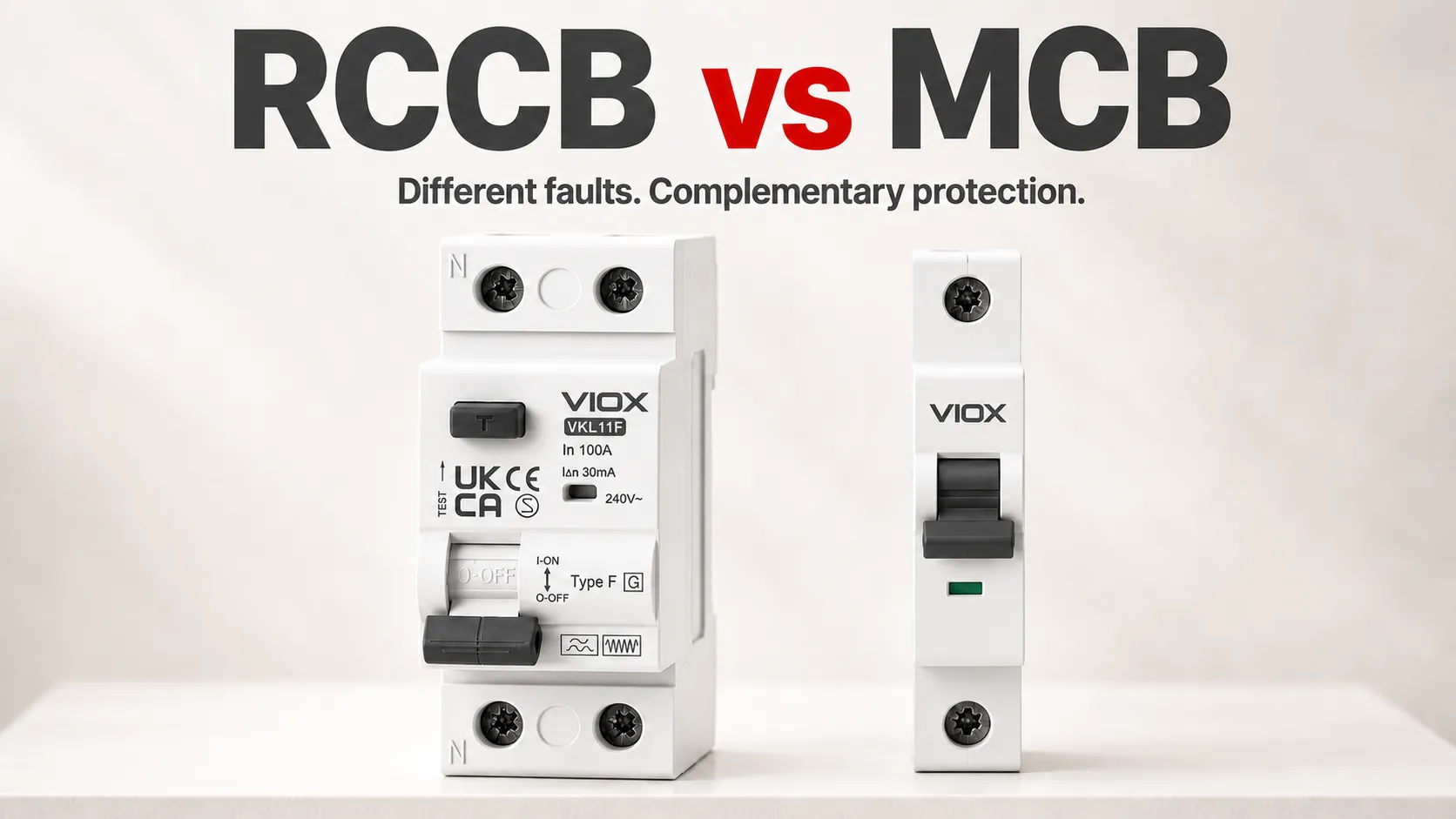
    An RCCB detects residual-current imbalance; an MCB protects against overload and short circuit. They are not substitutes. When a circuit needs both functions, use an RCCB with correctly coordinated overcurrent protection, such as MCBs, or a suitable RCBO that combines the functions in one device.

    “Why you need both” means both protection functions—not necessarily two separate devices. An RCCB’s contribution to shock protection depends on its sensitivity, the fault-current path, device type and correct installation. Neither device makes every electrical contact safe.

    RCCB vs MCB: The Core Difference

    The clearest comparison is the fault each device is designed to detect.

    Protection function or arrangement RCCB MCB RCCB + MCB RCBO
    Residual-current detection Yes No Yes Yes
    Overload protection No Yes Yes, through the MCB Yes
    Short-circuit overcurrent protection No Yes Yes, through the MCB Yes
    Additional shock protection With suitable sensitivity/type and installation conditions Not a substitute for high-sensitivity residual-current protection With suitable residual-current protection and coordination With suitable sensitivity/type and installation conditions
    Typical role Residual-current protection with separate overcurrent protection Branch-circuit overcurrent protection Separate devices providing complementary functions Combined protection for a circuit

    “Yes” identifies an available function, not proof that a particular device is suitable for every circuit. Ratings, fault level, earthing arrangement and manufacturer requirements still control selection. Schneider’s RCCB and RCBO explanation confirms the key boundary: an RCCB needs external overcurrent protection, while an RCBO integrates it.

    What Is the Function of an RCCB?

    An RCCB—Residual Current Circuit Breaker—monitors the sum of the currents in the live conductors passing through its sensing system. In a single-phase circuit, this is commonly described as comparing outgoing line current with returning neutral current. Current taking an unintended path outside that monitored circuit creates an imbalance; the device operates according to its residual-current characteristics.

    An MCB—Miniature Circuit Breaker—responds to overcurrent instead. A conventional thermal-magnetic MCB uses a thermal response for overload and a magnetic response for high short-circuit current. These are different detection tasks, which is why swapping one device for the other leaves a protection function missing.

    For the detailed operating principle, types and limitations, see What Is an RCCB? This comparison focuses on which functions your circuit needs.

    Why an MCB Does Not Replace RCCB Shock Protection

    A dangerous current through a person may be too small to operate an ordinary branch MCB. The absence of an MCB trip therefore does not show that a contact or earth-leakage condition is safe.

    However, “MCBs never protect people” is too broad. In a suitable TN earthing system, an overcurrent protective device can provide automatic disconnection for an earth fault when the fault-loop conditions produce enough current to meet the required disconnection time. That is different from high-sensitivity additional protection against contact with live parts. Electrical Installation Guide: TN protection principle.

    An RCCB’s shock-protection role also needs limits:

    • Sensitivity: RCDs rated at 30 mA or less are used for additional protection in applicable IEC-based arrangements. RCCBs with a higher rated residual operating current, such as 100 mA or 300 mA, are not equivalent for this purpose.
    • Fault path: the device must detect a residual imbalance. A line-to-neutral contact that returns all current through the monitored conductors may not create one.
    • Installation: correct protective measures, earthing and bonding where required, wiring and verification remain necessary. An RCCB does not replace them.
    • Device suitability: waveform type and operating characteristics must match the load and applicable installation requirements.

    High-sensitivity RCD protection is an additional measure, not a guarantee against injury or a replacement for basic protection. Electrical Installation Guide: additional protection.

    When Should You Use RCCB Instead of MCB?

    The wording needs one correction: add the missing residual-current protection function; do not remove necessary overcurrent protection.

    Circuit situation Practical decision
    Overcurrent protection is present, but required residual-current protection is missing Evaluate adding a coordinated RCCB arrangement or using an appropriate RCBO
    RCCB is present, but overload/short-circuit protection has not been established Verify and provide the necessary overcurrent protection; the RCCB alone is not enough
    Both functions are required for an individual final circuit Consider an appropriate RCBO or a coordinated RCCB + MCB arrangement
    Several circuits share an RCCB Assess the consequences of losing the whole group during a residual-current trip

    Bathrooms, outdoor circuits and other locations with increased shock exposure often require particular protective measures. The exact circuit coverage and device requirements come from the applicable local rules—not a universal room-by-room rule in this article.

    RCCB + MCB vs RCBO in Real Installations

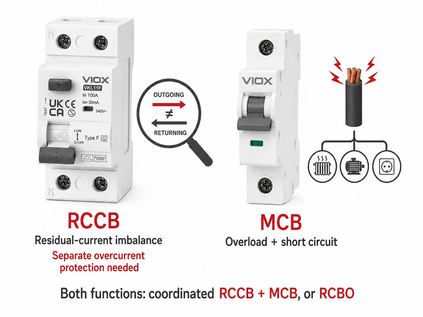
    VIOX RCCB and MCB product comparison showing residual-current imbalance versus overload and short-circuit protection

    The figure uses simplified product exteriors to compare functions; it is not a wiring diagram, a specification sheet or a statement that any two selected devices form an approved combination.

    With a shared RCCB and separate branch MCBs, the MCBs provide branch overcurrent protection while the RCCB provides residual-current protection for the group. A residual-current trip can disconnect multiple circuits. Separate per-circuit RCBOs can limit that shared-tripping impact, although upstream coordination still matters.

    Neither arrangement wins automatically on cost, space or selectivity. For those design tradeoffs, see RCBO vs RCCB + MCB: Space, Cost and Selectivity.

    Breaking Capacity and Backup Protection Still Matter

    Do not stop at the labels “RCCB + MCB.” Check:

    • the prospective short-circuit current at the installation point;
    • the breaking capacity of the overcurrent protective device;
    • the RCCB manufacturer’s permitted backup-protection combination and conditional short-circuit rating;
    • overload protection for the RCCB itself, considering the actual arrangement and loading.

    An RCCB’s ampere rating describes its rated current; it is not an overload trip setting. Its conditional short-circuit rating must not be treated as the same thing as an MCB’s standalone breaking capacity. Manufacturer coordination data determine the supported combination. ABB RCD technical guide.

    RCCB Selection Basics: What to Check Next

    Once the required functions are clear, selection becomes a specification task. Confirm rated current In, rated residual operating current IΔn, waveform type, pole count, voltage, time characteristics and overcurrent coordination. A 63 A marking and a 30 mA marking answer different questions; neither alone completes the selection.

    Modern electronic loads can affect the required residual-current type. Do not select Type AC, A, F or B solely by price or assume one type is a universal upgrade. Use the connected equipment instructions and applicable installation rules.

    Follow the complete How to Choose an RCCB workflow, then compare the VIOX RCCB product range against that specification. Installation or replacement should be carried out by a qualified electrical professional.

    Frequently Asked Questions

    Can an RCCB Replace an MCB?

    Not by itself. An RCCB does not provide the MCB’s overload and short-circuit functions. A suitable RCBO can combine residual-current and overcurrent protection, but replacement still requires checking the circuit and device specifications.

    Is an RCCB Better Than an MCB?

    Not overall. The RCCB detects residual-current imbalance; the MCB handles overcurrent. Choose the functions required by the circuit rather than treating either device as a universal winner.

    Why Does My RCCB Trip but the MCB Does Not?

    A residual-current imbalance can operate the RCCB without enough overcurrent to operate the MCB. That does not identify the fault location by itself. For investigation, see Why Does an RCCB Keep Tripping? Do not bypass protection or repeatedly reset an unresolved fault.

    What Is the Difference Between MCB and RCB?

    MCB identifies a miniature overcurrent circuit breaker. RCB is used less precisely in some markets for residual-current protection. For procurement, confirm whether the specified product is an RCCB without integral overcurrent protection or an RCBO with it.

    Do I Need Both RCCB and MCB If I Have an RCBO?

    An appropriate RCBO already provides both functions for its protected circuit. That does not automatically remove requirements for upstream isolation, backup protection or other system protection. Check the complete arrangement rather than duplicating devices merely because their names differ.

    Recommended Protection Strategy

    Use MCB protection for overload and short circuit, and provide suitable residual-current protection where required. When both functions are needed, choose a coordinated RCCB + MCB arrangement or an appropriate RCBO. The decision is not which name is “safer,” but whether the complete circuit has the required protection and verified coordination.

  • IP67 vs IP68: Complete Guide to Ingress Protection Ratings

    IP67 vs IP68: Complete Guide to Ingress Protection Ratings

    IP67 and IP68 are both waterproof ratings, but IP68 offers superior water protection. IP67 devices can withstand immersion in water up to 1 meter for 30 minutes, while IP68 devices can handle deeper water and longer submersion times as specified by the manufacturer. Both ratings provide complete dust protection.

    Understanding these ingress protection standards is crucial when selecting electronics for outdoor use, industrial applications, or water-exposed environments. The right IP rating ensures your equipment performs reliably while preventing costly damage from water and dust ingress.

    What Are IP Ratings? Essential Definitions

    IP Ratings

    Ingress Protection (IP) ratings are international standards defined by IEC 60529 that classify the degree of protection provided by electrical enclosures against intrusion of solid objects and liquids.

    The IP rating consists of two digits:

    • First digit (0-6): Protection against solid particles and dust
    • Second digit (0-9): Protection against water ingress

    IP67 Definition

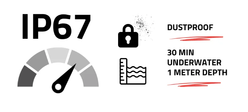
    IP67 rating means the device is completely dust-tight (6) and can withstand immersion in water up to 1 meter deep for up to 30 minutes (7).

    IP68 Definition

    ip68

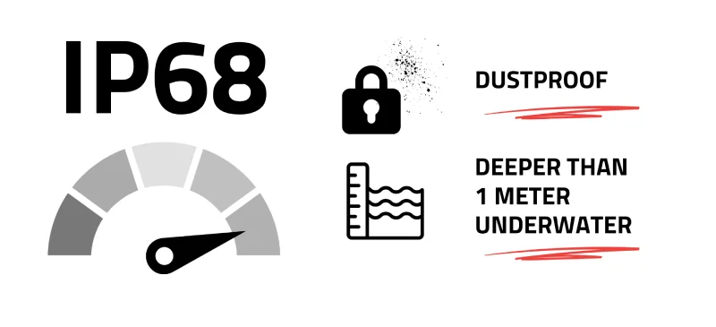
    IP68 rating means the device is completely dust-tight (6) and can withstand continuous immersion in water beyond 1 meter depth (8), with specific conditions defined by the manufacturer.

    IP67 vs IP68: Key Differences Comparison

    Feature IP67 IP68
    Dust Protection Complete protection (Level 6) Complete protection (Level 6)
    Water Depth Up to 1 meter Beyond 1 meter (manufacturer specified)
    Immersion Time Maximum 30 minutes Continuous (manufacturer specified)
    Typical Applications Smartphones, outdoor cameras Diving equipment, submarines
    Cost Factor Lower manufacturing cost Higher manufacturing cost
    Testing Standard IEC 60529 standardized IEC 60529 + manufacturer specifications
    Common Depths 0.15m to 1m testing 1.5m to 10m+ depending on design

    Detailed Water Protection Analysis

    IP67 Water Protection Specifications

    IP67 devices undergo standardized testing under these conditions:

    • Test duration: 30 minutes maximum
    • Water depth: 0.15 meters to 1 meter
    • Water temperature: Room temperature
    • Test method: Static immersion without water circulation

    ⚠️ Safety Note: IP67 rating does not guarantee protection against high-pressure water jets or dynamic water conditions.

    IP68 Water Protection Specifications

    IP68 testing varies by manufacturer but typically includes:

    • Test duration: Continuous immersion (hours to days)
    • Water depth: 1.5 meters to 10+ meters
    • Pressure resistance: Significantly higher than IP67
    • Test conditions: Often include circulation and pressure simulation

    Expert Tip: Always check manufacturer specifications for IP68 devices, as “IP68” alone doesn’t specify exact depth and duration limits.

    Applications and Use Cases

    When to Choose IP67

    IP67 is ideal for:

    • Smartphones and tablets for everyday water resistance
    • Outdoor security cameras in normal weather conditions
    • Industrial sensors in mildly wet environments
    • Automotive electronics exposed to rain and washing
    • Consumer electronics for pool-side or beach use

    When to Choose IP68

    IP68 is essential for:

    • Underwater photography equipment
    • Marine navigation instruments
    • Swimming pool lighting systems
    • Submersible pumps and sensors
    • Professional diving equipment
    • Underwater drones and ROVs

    Industry Applications Breakdown

    Consumer Electronics

    • Smartphones: Most flagship phones now offer IP67 or IP68
    • Smartwatches: Swimming-focused models typically use IP68
    • Action cameras: Professional models often exceed basic IP68 standards

    Industrial Applications

    • Process control sensors: IP68 for submerged monitoring
    • Outdoor networking equipment: IP67 sufficient for weather protection
    • Marine instruments: IP68 mandatory for continuous submersion

    Automotive Industry

    • Engine bay sensors: IP67 standard for normal operations
    • Underwater vehicle systems: Custom IP68+ ratings required

    Selection Criteria: How to Choose the Right Rating

    Step-by-Step Selection Process

    1. Assess your environment
      • Maximum expected water depth
      • Duration of potential water exposure
      • Presence of water pressure or jets
    2. Evaluate cost vs. benefit
      • IP67 offers excellent protection for most applications
      • IP68 required only when submersion exceeds IP67 limits
    3. Check manufacturer specifications
      • Verify exact depth and time ratings for IP68
      • Confirm testing standards and conditions
    4. Consider long-term reliability
      • IP68 typically offers better seal integrity over time
      • Higher initial cost may reduce replacement frequency

    Expert Decision Framework

    Choose IP67 when:

    • Water exposure is accidental or temporary
    • Budget constraints are significant
    • Standard weather protection is sufficient

    Choose IP68 when:

    • Intentional submersion is required
    • Continuous underwater operation needed
    • Maximum protection is worth additional cost

    Testing Standards and Certifications

    IEC 60529 Standard Requirements

    Both IP67 and IP68 must comply with International Electrotechnical Commission standards:

    Dust Testing (First Digit – 6):

    • Complete protection against dust ingress
    • 8-hour test in talcum powder chamber
    • No dust particles must penetrate enclosure

    Water Testing Procedures:

    • IP67: Immersion test at specified depths and duration
    • IP68: Extended immersion with manufacturer-defined parameters

    Professional Certification Process

    Devices must undergo testing at accredited laboratories:

    1. Pre-testing preparation: Seal integrity verification
    2. Environmental conditioning: Temperature and humidity cycling
    3. Immersion testing: Following exact protocol specifications
    4. Post-test inspection: Internal examination for water ingress
    5. Documentation: Detailed test reports and certifications

    Common Misconceptions and Clarifications

    Myth vs. Reality

    ❌ Myth: “IP68 is always better than IP67”

    ✅ Reality: IP68 costs more and may be unnecessary for many applications

    ❌ Myth: “IP ratings protect against all types of water exposure”

    ✅ Reality: High-pressure jets and steam may penetrate even IP68 devices

    ❌ Myth: “IP ratings are permanent and never degrade”

    ✅ Reality: Seals can deteriorate over time, requiring maintenance

    IP 68 Cable Gland

    Troubleshooting and Maintenance

    Signs of Compromised IP Protection

    Watch for these warning indicators:

    • Visible cracks in seals or gaskets
    • Fogging inside transparent housings
    • Corrosion around connection points
    • Reduced performance in humid conditions

    Maintenance Best Practices

    1. Regular seal inspection: Check gaskets every 6-12 months
    2. Proper cleaning: Use manufacturer-approved cleaning agents
    3. Temperature cycling: Avoid extreme temperature changes
    4. Professional servicing: Annual inspection for critical applications

    ⚠️ Safety Warning: Never attempt to service IP-rated enclosures without proper training and replacement seals meeting original specifications.

    Cost Analysis and ROI Considerations

    Price Impact Factors

    Factor IP67 Impact IP68 Impact
    Manufacturing complexity Moderate increase Significant increase
    Material costs Standard sealing materials Premium sealing systems
    Testing requirements Standard protocols Extended testing needed
    Design constraints Moderate limitations Significant design challenges

    Long-term Value Assessment

    IP67 ROI Benefits:

    • Lower initial investment
    • Adequate protection for most applications
    • Easier repairs and maintenance

    IP68 ROI Benefits:

    • Reduced replacement frequency
    • Higher equipment reliability
    • Expanded application possibilities

    Future-Proofing and Technology Trends

    Emerging Standards

    The electronics industry continues advancing IP protection:

    • Enhanced testing protocols for extreme environments
    • Smart sealing systems with self-monitoring capabilities
    • Nano-coating technologies complementing mechanical seals

    Industry Evolution

    Current trends affecting IP rating selection:

    • Increasing consumer demand for water-resistant devices
    • Stricter industrial safety requirements
    • Growing marine and underwater applications

    Quick Reference Guide

    IP67 vs IP68 Decision Checklist

    ✅ Choose IP67 if:

    • Water exposure limited to 1 meter depth
    • Immersion time under 30 minutes
    • Cost optimization is priority
    • Standard weather protection needed

    ✅ Choose IP68 if:

    • Submersion beyond 1 meter required
    • Continuous underwater operation needed
    • Maximum protection justifies higher cost
    • Professional/industrial application

    Emergency Assessment Questions

    1. What is the maximum water depth your device will encounter?
    2. How long might the device remain submerged?
    3. Will the device face high-pressure water exposure?
    4. What is your budget for protection vs. replacement costs?

    Frequently Asked Questions

    What is the main difference between IP67 and IP68?

    The primary difference is water protection depth and duration. IP67 protects against immersion up to 1 meter for 30 minutes, while IP68 allows deeper, longer submersion as specified by the manufacturer.

    Can IP67 devices be used underwater?

    Yes, but only temporarily. IP67 devices can handle underwater use up to 1 meter deep for maximum 30 minutes. For extended underwater use, choose IP68.

    Is IP68 always more expensive than IP67?

    Generally yes. IP68 requires more sophisticated sealing systems and extensive testing, resulting in higher manufacturing costs that are passed to consumers.

    Do IP ratings protect against saltwater?

    Both IP67 and IP68 testing typically uses fresh water. Saltwater is more corrosive and may require additional protection measures beyond standard IP ratings.

    How long do IP seals last?

    Seal lifespan depends on usage conditions, but typically ranges from 2-5 years for consumer devices and 5-10 years for industrial equipment with proper maintenance.

    Can I upgrade a device from IP67 to IP68?

    No. IP ratings are determined by the original design and manufacturing. Retrofitting different sealing systems would require complete redesign and recertification.

    What happens if water gets inside an IP-rated device?

    Immediately power down the device, remove batteries if possible, and seek professional service. Water damage often voids warranties even on IP-rated devices if the damage indicates seal failure.

    Are there IP ratings higher than IP68?

    IP68 is the highest standard water protection rating. Some manufacturers use proprietary ratings like “IP69K” for specific high-pressure applications, but these aren’t standard classifications.

    Expert Recommendations and Professional Guidance

    Professional Installation Considerations

    When specifying IP-rated equipment for commercial or industrial applications:

    1. Consult certified installers familiar with IP rating requirements
    2. Verify local compliance codes that may mandate specific protection levels
    3. Document installation procedures to maintain warranty coverage
    4. Plan maintenance schedules to preserve IP protection over time

    When to Consult Specialists

    Seek professional advice for:

    • Critical safety applications where failure could cause injury
    • Installations requiring compliance with specific industry standards
    • Custom applications exceeding standard IP rating parameters
    • High-value equipment where protection investment is justified

    ⚠️ Professional Recommendation: For mission-critical applications, consider IP ratings as minimum requirements and evaluate additional protective measures based on specific operational conditions.

    Final Recommendation: Choose IP67 for general water resistance needs and IP68 only when specific submersion requirements justify the additional cost. Both ratings provide excellent dust protection, making your decision primarily about water exposure depth and duration requirements.

    Understanding these ingress protection standards ensures you select equipment that delivers reliable performance while avoiding unnecessary costs or inadequate protection for your specific application needs.

    Related

    Waterproof Junction Box

    Applications of Waterproof Cable Glands

  • Smart vs Traditional vs Solid-State Circuit Breakers: Differences, Tradeoffs, and When Each Makes Sense

    Smart vs Traditional vs Solid-State Circuit Breakers: Differences, Tradeoffs, and When Each Makes Sense

    The difference between a smart circuit breaker and a traditional circuit breaker is not the same as the difference between an electromechanical breaker and a solid-state circuit breaker. These labels describe two different design questions:

    • How does the device interrupt current? An electromechanical breaker opens physical contacts; a semiconductor circuit breaker interrupts through power electronic devices; a hybrid design combines semiconductor and mechanical paths.
    • How much intelligence does it add? Monitoring, communications, remote operation, event logs, and programmable control can be added to more than one interruption architecture.

    That distinction changes the buying decision. A smart breaker may still use conventional mechanical contacts, while a solid-state circuit breaker may also be connected and software-configurable. The correct choice depends on the required protection function, fault-clearing behavior, isolation, normal-state losses, system integration, product certification, and lifecycle support—not on whether the device has an app.

    The Two-Axis Classification That Prevents the Most Common Mistake

    The term traditional circuit breaker normally refers to an electromechanical device whose main contacts physically separate to interrupt current. Fault sensing may be thermal-magnetic or electronic; “traditional” does not necessarily mean that every internal function is purely mechanical.

    A smart circuit breaker adds sensing, communications, data, control, or automation. Its main current path may still be electromechanical. In other products, a separate connected module monitors or switches a circuit while a conventional breaker remains the actual overcurrent protective device.

    A solid-state circuit breaker (SSCB)—called a semiconductor circuit-breaker in IEC 60947-10:2026—uses semiconductor switching elements for current interruption. The standard also recognizes semiconductor hybrid circuit-breakers, which combine semiconductor and mechanical switching elements and include mechanical isolation contacts.

    The practical classification is therefore:

    Main interruption architecture No connected intelligence Connected or programmable intelligence
    Electromechanical contacts Conventional thermal-magnetic or electronic-trip breaker Smart/connected electromechanical breaker
    Semiconductor switching with mechanical isolation Basic semiconductor circuit-breaker Smart solid-state circuit breaker
    Hybrid semiconductor and mechanical paths Hybrid breaker Smart hybrid breaker

    “Smart” describes capabilities. “Solid-state” describes the main interruption technology. A product can be both.

    Two-axis classification of circuit breakers by interruption technology and connected intelligence.

    Traditional vs Smart vs Solid-State: Engineering Comparison

    Decision factor Conventional electromechanical breaker Smart or connected breaker Semiconductor or hybrid breaker
    Main distinguishing feature Proven mechanical interruption and local protection Monitoring, communications or remote control added to a protection or switching system Semiconductor fault interruption; hybrid versions add mechanical switching paths
    Fault interruption Physical contacts open and an arc-control system interrupts current Depends on the underlying breaker architecture Semiconductor switching can interrupt without waiting for mechanical contact travel
    Protection function Defined by the breaker design, trip unit, ratings and applicable product standard Must be verified; connectivity alone does not prove overcurrent protection Must be verified against the relevant semiconductor-breaker standard and product documentation
    Normal-state power loss Generally low across closed contacts Similar to the underlying breaker, plus auxiliary electronics Semiconductor conduction losses require thermal consideration; hybrid designs may reduce steady-state loss
    Isolation A breaker may be suitable for isolation only when its design, marking and instructions say so Remote OFF is not automatically an isolation state Semiconductor blocking alone is not a verified isolation function; applicable standards may require mechanical isolation contacts
    Monitoring and data Usually limited unless accessories or an electronic trip unit are fitted Common reason for choosing the architecture Can be integrated with high-speed sensing and programmable control
    Remote operation Requires a suitable motor operator, shunt trip, undervoltage release or other approved mechanism Often available, but closing, opening and automatic reclosing permissions must be checked Inherent electronic control is possible, while safe isolation remains a separate requirement
    Behavior if communications fail Local protection remains independent of a network Must be checked: protective operation, local control and safe state should not be assumed from marketing language Control-power loss and internal electronic faults are part of the product safety assessment
    Retrofit and panel fit Mature, but the exact breaker must be compatible with the assembly Ecosystem, gateway, panel and firmware compatibility can limit retrofit options Usually a system-engineering decision rather than a drop-in replacement
    Typical decision driver Cost-effective, mature circuit protection Visibility, remote operation, energy data or load management Very fast interruption, controllable protection and demanding DC or power-electronic systems

    The table is an architecture guide, not a substitute for a model datasheet. Rated voltage, rated current, breaking capacity, trip characteristics, environmental limits, isolation function, panel compatibility and certifications remain product-specific.

    When a Conventional Electromechanical Breaker Makes Sense

    A conventional breaker remains the default choice when the primary requirement is dependable overcurrent protection with low normal-state loss and no need for remote visibility.

    It is usually the strongest fit when:

    • protection requirements are already met by an established MCB or MCCB architecture;
    • local manual operation is acceptable;
    • the panel does not need circuit-level energy data;
    • simple maintenance and long-term replacement availability matter more than connected features;
    • the application needs a mature and widely understood product-standard route.

    This does not mean conventional breakers are technically simple. Electronic-trip MCCBs can provide adjustable protection, event information and communications while still using mechanical contacts for interruption. The more useful distinction is mechanical interruption versus semiconductor interruption, not “old” versus “digital.”

    For a broader map of protective-device families, see the VIOX guide to types of circuit breakers.

    When a Smart Circuit Breaker Is Worth Considering

    A smart breaker is worth considering when its data or control function solves a defined operational problem. Examples include identifying heavily loaded circuits, reporting trip events, scheduling noncritical loads, coordinating on-site generation and storage, or allowing an approved supervisory system to open selected circuits.

    Before treating a connected DIN-rail device as a circuit breaker, verify four separate functions:

    1. Protection: Does the exact device provide the required automatic overcurrent protection, or is it only a connected switch, relay, meter, or controller?
    2. Interruption: What mechanism clears a fault, and what are the marked interrupting ratings?
    3. Control: Which functions remain available locally if a gateway, network or cloud service is unavailable?
    4. Compatibility: Is the device approved for the panel, assembly, conductors, voltage and intended installation?

    The word “smart” does not establish any of these points. A smartphone interface can control a device without making it an acceptable branch-circuit protective device. Likewise, energy monitoring does not prove short-circuit interruption capability.

    Remote operation also needs careful wording. Opening a circuit remotely may be useful for load management, but it does not automatically create a safe isolation condition for maintenance. The device marking, product standard, instructions and installation procedure determine whether it is suitable for isolation.

    When a Solid-State or Hybrid Breaker Makes Sense

    Semiconductor circuit-breakers are most relevant when system behavior during the first moments of a fault matters more than minimum conduction loss or lowest initial cost. Their electronic switching path can support rapid fault response, programmable behavior and integration with high-speed sensing.

    Their tradeoffs are equally important:

    • semiconductor devices dissipate power while carrying load current;
    • heat sinking and enclosure thermal design become part of the protection system;
    • overvoltage produced when interrupting inductive current must be managed;
    • auxiliary control power, software behavior and internal component failures require verification;
    • a semiconductor OFF or standby state is not automatically equivalent to mechanical isolation;
    • certification and application maturity may differ from established MCB and MCCB products.

    IEC 60947-10:2026 now provides an international standard scope for semiconductor circuit-breakers and semiconductor hybrid circuit-breakers up to 1,000 V AC or 1,500 V DC for operation by instructed or skilled persons. In North American contexts, UL Solutions describes UL 489I as an evaluation path used alongside UL 489 for solid-state and hybrid molded-case circuit breakers.

    For a deeper explanation of semiconductor switching, fault energy and thermal design, use the separate VIOX guide to solid-state circuit breakers. This comparison page intentionally stops at the selection boundary.

    Functional comparison of electromechanical, smart connected, and semiconductor hybrid breaker architectures.

    Which Architecture Fits the Application?

    Application need Reasonable starting architecture What must be verified before selection
    Ordinary final distribution without remote monitoring Conventional MCB or other appropriate electromechanical breaker Circuit rating, cable protection, breaking capacity, trip curve, pole configuration and applicable installation rules
    Industrial feeder requiring adjustable protection and communications Electronic-trip electromechanical MCCB with supported accessories or communications Trip-unit functions, communication architecture, auxiliary power, selectivity and assembly compatibility
    Circuit-level energy monitoring and controlled load shedding Smart breaker or approved combination of breaker, metering and switching devices Which component provides protection, local fallback behavior, switching duty, panel approval and cybersecurity lifecycle
    Remote opening of selected loads Smart breaker or breaker with an approved remote-operating accessory Whether remote closing is permitted, control-power behavior, interlocks and whether OFF provides isolation
    Fast protection of sensitive DC power electronics Semiconductor or hybrid circuit-breaker may justify evaluation DC voltage, fault-current rise, interruption rating, energy absorption, thermal design, isolation and certification
    Cost-sensitive, low-complexity protection Conventional electromechanical breaker Correct rating and verified compatibility; do not add connectivity without a defined operating benefit

    There is no universal winner. Conventional breakers optimize maturity, low loss and straightforward protection. Smart breakers are justified when information or control produces a measurable operational benefit. Semiconductor and hybrid breakers are justified when their interruption behavior solves a fault-protection problem that a conventional architecture cannot address as effectively.

    Standards and Certification Boundaries

    The correct standard cannot be selected from the word “smart” alone.

    Standard or route Relevant boundary
    IEC 60898-1:2015+A1:2019 AC air-break circuit-breakers for household and similar installations within the standard’s voltage, current and short-circuit-capacity limits
    IEC 60947-2:2024 Low-voltage circuit-breakers intended for operation by instructed or skilled persons, within its stated AC and DC voltage scope
    IEC 60947-10:2026 Semiconductor circuit-breakers and semiconductor hybrid circuit-breakers, including isolation and abnormal-condition requirements
    UL 489 North American molded-case circuit-breakers, switches and enclosures within the applicable product category
    UL 489I Solid-state and solid-state hybrid molded-case circuit breakers evaluated within the UL route described by UL Solutions

    A wireless radio approval, app certification or generic conformity mark does not by itself prove that the device is acceptable as the required circuit breaker. Ask for the exact model’s certificate or listing, applicable product standard, marked ratings, installation instructions and assembly compatibility.

    The UL circuit-breaker marking guide also distinguishes a semiconductor-control STANDBY position from the OFF state required before work on the load side. That is a useful reminder that software control and electrical isolation are different safety functions.

    For a detailed comparison of the two main IEC breaker contexts, see IEC 60898-1 vs IEC 60947-2. For North American terminology and product-standard boundaries, use the VIOX guide to UL, NEC, NEMA and ANSI circuit-breaker standards.

    Procurement Checklist: Verify the Device, Not the Label

    Before approving any traditional, smart, solid-state or hybrid breaker, obtain evidence for:

    • the exact protective functions provided by the device;
    • interruption architecture and isolation method;
    • rated voltage, rated current and AC/DC application;
    • breaking or interrupting rating under the applicable standard;
    • trip characteristic or programmable protection settings;
    • conductor, terminal and enclosure requirements;
    • compatibility with the panelboard or switchgear assembly;
    • behavior after loss of auxiliary power or communications;
    • local operation, remote opening, remote closing and automatic-reclosing permissions;
    • firmware update, access-control and support policy for connected products;
    • model-specific certification, listing or test documentation;
    • thermal-loss and cooling requirements for semiconductor designs.

    Choose a conventional breaker when protection is the only task. Choose a smart architecture when verified monitoring or control is worth the added system dependency. Evaluate a semiconductor or hybrid breaker when faster electronic interruption and programmability justify the thermal, integration and certification work. In every case, the model’s verified protective function matters more than the label printed on the product page.

  • UL 94 V-0 vs V-1 vs V-2: Ratings and Test Criteria

    UL 94 V-0 vs V-1 vs V-2: Ratings and Test Criteria

    UL 94 V-0, V-1, and V-2 are classifications from the 50 W, 20 mm vertical burning test for polymeric materials. V-0 has the shortest permitted afterflame times. V-1 allows longer times but does not permit flaming drips that ignite the cotton indicator. V-2 uses the same time limits as V-1 but permits those flaming drips.

    These classifications describe the behavior of evaluated specimens under controlled, small-scale test conditions. They are not finished-product fire ratings, and a result applies only within the recognized material, thickness, color, conditioning, and other limitations recorded for that evaluation.

    UL 94 V-0, V-1, and V-2 Criteria at a Glance

    The vertical test applies the specified flame twice to each specimen and records afterflame, afterglow, burning progression, and flaming drips. The complete classification criteria are:

    Test criterion V-0 V-1 V-2
    Afterflame time after either flame application, for each specimen 10 seconds maximum 30 seconds maximum 30 seconds maximum
    Total afterflame time for the set of five specimens across 10 flame applications 50 seconds maximum 250 seconds maximum 250 seconds maximum
    Afterflame plus afterglow after the second flame application, for each specimen 30 seconds maximum 60 seconds maximum 60 seconds maximum
    Flaming or glowing combustion reaches the holding clamp Not permitted Not permitted Not permitted
    Flaming drips ignite the cotton indicator Not permitted Not permitted Permitted
    UL 94 V-0, V-1, and V-2 vertical burning test criteria comparison

    The word permitted does not mean every V-2 specimen must ignite the cotton. It means cotton ignition by flaming particles does not automatically prevent a V-2 classification when the other V-2 criteria are satisfied.

    The practical hierarchy within this one test method is therefore V-0, then V-1, then V-2. That hierarchy should not be extended indiscriminately to HB, VTM, HF, or 5V classifications because those names belong to different specimen types or test methods.

    What a UL 94 Classification Does—and Does Not—Prove

    UL 94 is often reduced to two characters on a datasheet, but the scope boundary matters as much as the classification.

    Question Correct interpretation
    What does the test evaluate? How a polymeric specimen burns, self-extinguishes, glows, and drips after exposure to a defined ignition source under controlled conditions.
    What does V-0, V-1, or V-2 prove? The evaluated specimens met the criteria for that classification at the reported conditions and thickness.
    Does the rating certify a complete enclosure, terminal block, switch, or appliance? No. End-product suitability depends on the applicable product standard, construction, component position, and certification program.
    Does V-0 mean the material will not ignite? No. The test begins by applying a flame. The classification describes behavior after and during the specified exposure; it does not mean noncombustible or fireproof.
    Does the result predict a large or developing fire? No. UL 94 uses small-scale laboratory tests and does not reproduce every real fire condition.
    Does the rating cover smoke, toxicity, heat release, electrical performance, or weathering? Not by itself. Those properties require other evaluations when they matter to the end product.

    This boundary prevents a common specification error: writing “UL 94 V-0 product” without identifying whether the requirement applies to a polymeric material, a recognized component, or the complete end product.

    How the 50 W Vertical Test Produces a Classification

    In the UL 94 V test, a polymer specimen is held vertically. A 20 mm test flame with nominal thermal power of 50 W is applied to the lower end for 10 seconds and removed. After the first afterflame ends, the flame is applied a second time for 10 seconds.

    The observations are not limited to a single “self-extinguishing time.” The classification uses:

    • the afterflame time following each application;
    • the total afterflame time across the complete specimen set;
    • afterflame plus afterglow following the second application;
    • whether combustion progresses to the holding clamp; and
    • whether flaming drops ignite the cotton indicator below the specimen.

    UL Solutions also describes two conditioning regimes for the test sets: 48 hours at 23°C and 50% relative humidity, and seven days in a 70°C hot-air oven. Engineers should use the applicable standard and laboratory or recognition record for the complete preparation and acceptance procedure rather than treating this article as a laboratory instruction.

    V-0 vs V-1: The Difference Is More Than One Time Limit

    V-0 and V-1 both prohibit flaming drips that ignite the cotton indicator and both prohibit combustion from reaching the holding clamp. Their differences are the permitted time limits:

    • V-0: no individual afterflame time may exceed 10 seconds, and the total for 10 flame applications may not exceed 50 seconds.
    • V-1: an individual afterflame time may be as long as 30 seconds, and the total may be as high as 250 seconds.
    • The afterflame-plus-afterglow limit following the second application is 30 seconds for V-0 and 60 seconds for V-1.

    A V-0 result is therefore stricter within the V-series method, but “stricter” is not the same as “required.” The minimum acceptable classification must come from the applicable end-product or component requirements.

    V-1 vs V-2: Timing Is the Same; Cotton Ignition Is Different

    V-1 and V-2 share the same three time limits: 30 seconds for each afterflame period, 250 seconds in total, and 60 seconds for afterflame plus afterglow after the second application. Both also prohibit combustion from reaching the clamp.

    The distinguishing criterion is flaming drips:

    • V-1 does not permit flaming drops to ignite the cotton indicator.
    • V-2 permits cotton ignition by flaming drops.

    This is why “V-2 burns for 30 seconds while V-1 burns for less” is an incomplete explanation. A specimen can satisfy the V-1 timing limits yet be classified V-2 because of flaming-drip behavior.

    V-0 vs V-2: Both Time and Dripping Criteria Change

    Compared with V-2, V-0 imposes shorter individual and total afterflame limits, a shorter afterflame-plus-afterglow limit, and the prohibition on flaming drips igniting cotton. The two classifications therefore differ in more than a simple 10-second-versus-30-second headline.

    For a buyer, however, the label alone still does not complete the decision. A V-0 result at one thickness cannot automatically replace a V-2 result at another thickness, and neither result establishes that the material meets every requirement of the finished component.

    Thickness, Color, and Formulation Are Part of the Rating

    A UL 94 classification belongs to an evaluated material construction, not to a generic polymer name. “Polycarbonate V-0” or “nylon V-2” is not enough information for a defensible specification.

    At minimum, verify:

    • the material manufacturer and exact grade designation;
    • the classification and the minimum recognized thickness or thickness range;
    • the recognized colors or whether the record covers all colors;
    • formulation or processing limitations relevant to the supplied material; and
    • the applicable UL recognition record or Yellow Card.

    A grade may achieve one classification at a thicker specimen and another at a thinner specimen. Colorants, additives, fillers, recycled content, or other formulation changes may also fall outside the evaluated recognition. The fact that two products share the same base polymer does not transfer a classification from one grade to the other.

    UL Solutions’ Yellow Card provides a digital record of safety- and performance-related properties for a recognized polymeric material. Procurement documentation should match the supplier, grade, color coverage, and thickness used in the actual part rather than merely attaching an unrelated V-0 certificate.

    UL 94 is also only one material-selection input. An enclosure, for example, may require mechanical, ultraviolet, ingress, temperature, chemical, and electrical properties in addition to flammability. The VIOX electrical enclosure material selection guide covers that broader decision. The same multi-property principle applies when selecting cable gland materials.

    UL 94 Classification Families Are Not One Universal Ladder

    UL 94 contains multiple test families for different specimen forms and ignition conditions. Similar-looking suffixes do not make the results interchangeable.

    Classification family Main specimen or test context Key interpretation boundary
    HB Horizontal burning of solid polymer specimens Reports controlled horizontal burning behavior; it is not a failed or abbreviated V test.
    V-0, V-1, V-2 50 W, 20 mm vertical burning test for self-supporting specimens Compare these three only within the V-series criteria and recognized thickness.
    5VA, 5VB 500 W, 125 mm vertical test with additional plaque observations Uses a substantially more severe ignition source and different criteria; 5VA and 5VB are not obtained by simply extending the V test time.
    VTM-0, VTM-1, VTM-2 Thin materials that generally cannot support themselves in the standard vertical position VTM-0 is not equivalent to V-0 because the specimen preparation and test method differ.
    HBF, HF-1, HF-2 Low-density foam materials These classifications should not be substituted directly for V classifications on solid self-supporting parts.
    UL 94 test-family selection and rating-evidence verification framework

    This family map also explains why a search for UL 94 HF-1 or UL 94 VTM-0 should not be answered by copying the V-0/V-1/V-2 table. The test method must match the material form.

    A Five-Field Evidence Check for Engineers and Buyers

    Before accepting a UL 94 claim on a quotation, drawing, or material datasheet, record these five fields:

    Field Evidence to request Why it matters
    1. Governing requirement Applicable end-product/component standard and required flammability class Prevents choosing a classification based on habit rather than the actual compliance path.
    2. Material identity Manufacturer and exact material grade Prevents transferring a result between different formulations.
    3. Recognized thickness Minimum thickness or recognized thickness range Confirms the molded wall is within the evaluated range.
    4. Color/formulation coverage Recognized color entry and relevant additive or processing limitations Prevents an unrecognized colorant or modification from being treated as automatically covered.
    5. Recognition record Current Yellow Card, UL Product iQ record, or evidence required by the certification program Connects the claim to the evaluated material rather than an unsupported datasheet statement.

    If any field is missing, write the missing item into the RFQ or approval record. Do not repair the gap by assuming that V-0 at one thickness, in one color, or from one supplier covers all versions of the material.

    Common UL 94 Misinterpretations

    “V-0 means the plastic is fireproof”

    Incorrect. V-0 is a small-scale flammability classification under specified test conditions. It does not mean the material cannot ignite, cannot burn, or will provide a particular fire-resistance duration in a finished assembly.

    “Every V-0 grade is suitable wherever V-0 is specified”

    Incorrect. The material identity, recognized thickness, color, and end-product conditions still have to match.

    “VTM-0 is another way of writing V-0”

    Incorrect. VTM classifications apply to thin materials tested with a different procedure. UL Solutions explicitly states that VTM-0, VTM-1, and VTM-2 cannot be considered equivalent to their V-series namesakes.

    “UL 94 and IEC 60695-11-10 reports are automatically interchangeable”

    Incorrect. IEC 60695-11-10 defines related 50 W horizontal and vertical small-flame methods, and UL Solutions lists it as a corresponding test framework. The required certification or recognition evidence still depends on the market, end-product standard, and conformity-assessment route. Confirm acceptance rather than substituting one report by name alone.

    Frequently Asked Questions

    Is UL 94 V-0 better than V-1 and V-2?

    V-0 is the strictest of these three classifications within the same 50 W vertical test because it has shorter time limits and does not permit flaming drips to ignite cotton. Whether it is the correct requirement depends on the applicable end-product or component standard.

    What does 94V-0 mean?

    94V-0, UL 94 V-0, and UL94 V0 are commonly used to refer to the V-0 vertical-burning classification. For procurement, use the formal classification together with the exact material grade and recognized thickness.

    Can a material’s UL 94 rating change with thickness?

    Yes. The reported classification is thickness-dependent. A grade recognized as V-0 at one thickness may have a different classification, or no relevant recognition, at a thinner section. Verify the minimum thickness or range on the recognition record.

    Is UL 94 VTM-0 equivalent to UL 94 V-0?

    No. VTM-0 is for thin materials that generally cannot support themselves in the standard V test. The procedures differ, so the classifications are not interchangeable.

    Primary References

  • Short Circuit vs Earth Fault vs Overload: Which Electrical Fault Is Most Dangerous?

    Short Circuit vs Earth Fault vs Overload: Which Electrical Fault Is Most Dangerous?

    Electrical faults are responsible for thousands of fires and injuries each year, but not all electrical problems carry the same level of risk. Whether you’re a homeowner concerned about electrical safety or a professional electrician, understanding the differences between short circuits, earth faults, and overloads could save lives and prevent costly damage.

    This comprehensive guide examines each type of electrical fault, their relative dangers, and most importantly—how to prevent them from occurring in your electrical systems.

    Understanding the Three Most Common Electrical Faults

    short circuit

    What Is a Short Circuit?

    A short circuitoccurs when electrical current takes an unintended path with little or no resistance, bypassing the normal circuit route. This happens when:

    • Live wires come into direct contact with neutral wires
    • Insulation breaks down between conductors
    • Metal objects bridge across electrical connections
    • Faulty wiring creates unintended connections

    Immediate Effects:

    • Massive current surge (often 10-100 times normal current)
    • Intense heat generation
    • Bright flash or arc
    • Circuit breaker trips instantly
    • Potential for explosion or fire

    What Is an Earth Fault?

    Anearth fault (also called ground fault) happens when electrical current flows from a live conductor to the earth or grounding system instead of returning through the neutral conductor. Common causes include:

    • Damaged insulation allowing current to reach metal casings
    • Moisture infiltration in electrical equipment
    • Deteriorated wiring touching grounded surfaces
    • Faulty appliances with compromised insulation

    Immediate Effects:

    • Current leakage to ground
    • Potential for electric shock
    • RCD/GFCI protection typically activates
    • Equipment malfunction
    • Fire risk in dry conditions

    What Is an Overload?

    An overload occurs when an electrical circuit carries more current than it was designed to handle safely. This typically results from:

    • Too many devices connected to one circuit
    • Appliances drawing more power than expected
    • Undersized wiring for the electrical load
    • Gradual deterioration reducing circuit capacity

    Immediate Effects:

    • Excessive heat buildup in conductors
    • Insulation degradation over time
    • Circuit breaker trips (may be delayed)
    • Reduced equipment lifespan
    • Fire risk from overheated components
    rcbo in panel

    Comparative Analysis: Which Fault Is Most Dangerous?

    Fault Type Speed of Onset Current Magnitude Fire Risk Shock Risk Detection Difficulty
    Short Circuit Instantaneous Extremely High Very High Moderate Easy (immediate)
    Earth Fault Variable Low to Moderate Moderate Very High Moderate
    Overload Gradual Moderately High High Low Difficult (gradual)

    Short Circuit: The Most Immediately Destructive

    Why short circuits top the danger list:

    Short circuits pose the highest immediate risk due to their explosive nature and massive current surges. When a short circuit occurs:

    • Current can increase by 1000% or more within milliseconds
    • Temperatures can exceed 3000°F at the fault point
    • Arc flash can cause severe burns to anyone nearby
    • Equipment destruction is often instantaneous and complete

    However, modern electrical systems are well-equipped to handle short circuits with fast-acting circuit breakers and fuses that typically clear the fault within 1-3 cycles (0.02-0.05 seconds).

    Earth Fault: The Silent Killer

    Why earth faults are deceptively dangerous:

    While earth faults may seem less dramatic, they present unique risks:

    • Electrocution hazard is highest because current flows through unintended paths
    • Can persist undetected for extended periods
    • May not trip standard circuit breakers if current isn’t excessive
    • Creates ongoing fire risk in combustible environments

    Earth faults are particularly dangerous because they can energize metal surfaces that people might touch, creating lethal shock hazards.

    Overload: The Slow Burn Threat

    Why overloads shouldn’t be underestimated:

    Overloads are dangerous primarily because of their insidious nature:

    • Heat builds gradually, making detection difficult
    • Insulation deteriorates slowly, reducing system safety over time
    • May not trigger immediate protection, allowing damage to accumulate
    • Creates conditions that can lead to short circuits or earth faults

    Real-World Scenarios and Case Studies

    Residential Short Circuit Incident

    Case: A homeowner’s attempt to install a ceiling fan resulted in reversed wire connections, creating a direct short between live and neutral conductors.

    Outcome: The 20-amp breaker tripped immediately, preventing fire. However, the electrical box sustained minor heat damage, and the incorrect wiring could have caused serious injury if protective devices hadn’t functioned properly.

    Key Lesson: Even “minor” electrical work requires proper knowledge and adherence to safety protocols.

    Commercial Earth Fault Emergency

    Case: A restaurant’s food preparation area experienced an earth fault when a damaged extension cord created a path to ground through the metal sink.

    Outcome: An employee received a severe shock when touching the sink while the fault was active. The GFCI protection hadn’t been installed in the older building, allowing the dangerous condition to persist.

    Key Lesson: Earth fault protection (GFCI/RCD) is critical in areas where water and electricity coexist.

    Industrial Overload Scenario

    Case: A manufacturing facility gradually added equipment to existing circuits over several years without upgrading electrical infrastructure.

    Outcome: Chronic overloading caused insulation failure, leading to multiple equipment failures and a production shutdown lasting three days.

    Key Lesson: Electrical systems must be evaluated and upgraded as loads increase over time.

    Prevention Strategies for Each Fault Type

    Short Circuit Prevention

    Installation Best Practices:

    • Use proper wire nuts and junction boxes for all connections
    • Maintain adequate spacing between conductors
    • Employ appropriate insulation ratings for environmental conditions
    • Follow manufacturer torque specifications for terminal connections

    Maintenance Requirements:

    • Regular inspection of electrical panels and junction boxes
    • Thermal imaging to detect hot spots indicating loose connections
    • Replacement of aging components before failure
    • Professional electrical audits every 5-10 years

    Earth Fault Prevention

    Essential Protection Measures:

    • Install GFCI/RCD protection in all required locations
    • Regular testing of ground fault protection devices (monthly)
    • Proper grounding of all electrical equipment and systems
    • Immediate repair of damaged cord and equipment insulation

    Environmental Considerations:

    • Moisture control in electrical areas
    • Proper sealing of outdoor electrical connections
    • Use of appropriate IP-rated equipment for harsh environments
    • Regular inspection of buried cable systems

    Overload Prevention

    System Design Principles:

    • Proper load calculations during initial installation
    • Adequate circuit capacity for anticipated growth
    • Use of appropriate wire sizes for expected loads
    • Installation of properly rated protective devices

    Ongoing Management:

    • Regular monitoring of circuit loading
    • Load balancing across available circuits
    • Timely electrical system upgrades as needs grow
    • Education of users about electrical capacity limits

    Modern Protection Technologies

    Circuit Breakers and Fuses

    Standard Protection:

    • Thermal-magnetic breakers respond to both overloads and short circuits
    • Electronic breakers provide precise trip curves and advanced features
    • Arc fault circuit interrupters (AFCI) detect dangerous arcing conditions
    • Combination AFCI/GFCI devices provide comprehensive protection

    Advanced Monitoring Systems

    Smart Electrical Panels:

    • Real-time current monitoring for all circuits
    • Automated alerts for unusual electrical activity
    • Historical data analysis for predictive maintenance
    • Remote monitoring capabilities for commercial applications

    Power Quality Analyzers:

    • Continuous monitoring of voltage, current, and power factor
    • Detection of electrical disturbances before they cause problems
    • Integration with building management systems
    • Automated reporting for maintenance planning

    Professional vs. DIY Electrical Work

    When to Call a Professional

    Always require professional installation:

    • Service panel upgrades or modifications
    • New circuit installation
    • Electrical system troubleshooting
    • Code compliance inspections
    • Industrial or commercial electrical work

    Safe DIY Electrical Practices

    Appropriate homeowner tasks:

    • Replacing outlets and switches (with power off)
    • Installing basic light fixtures
    • Connecting appliances to existing outlets
    • Basic electrical maintenance and cleaning

    Essential Safety Rules:

    • Always turn off power at the breaker
    • Test circuits with a non-contact voltage tester
    • Use appropriate personal protective equipment
    • Never work on electrical systems during storms
    • When in doubt, consult a professional

    Frequently Asked Questions

    Which electrical fault causes the most house fires?

    Overloads and short circuits are responsible for the majority of electrical fires. According to the National Fire Protection Association, electrical failures cause an estimated 13% of home structure fires annually, with overloaded circuits and short circuits being the primary culprits.

    Can I reset a breaker that keeps tripping?

    Never repeatedly reset a tripping breaker without identifying and correcting the underlying problem. A breaker that trips multiple times indicates a serious electrical fault that requires professional diagnosis. Continuing to reset the breaker can lead to fire or equipment damage.

    How often should electrical systems be inspected?

    Residential systems should be professionally inspected every 10 years, or when purchasing a home. Commercial and industrial systems require annual inspections, with critical systems inspected quarterly.

    What’s the difference between a short circuit and an earth fault?

    A short circuit involves current flowing between live and neutral conductors with minimal resistance, while an earth fault involves current flowing from a live conductor to ground. Short circuits typically cause immediate, dramatic failures, while earth faults may persist undetected and create ongoing shock hazards.

    Why don’t overloads always trip circuit breakers?

    Circuit breakers have thermal elements that respond to heat buildup from overcurrent conditions. If an overload is just slightly above the breaker’s rating, it may take minutes or even hours to generate enough heat to trigger the thermal element. This delayed response allows chronic overloading to damage wiring before protection activates.

    Are GFCI outlets enough protection against earth faults?

    GFCI outlets provide excellent protection against ground faults in their immediate area, but they don’t protect entire circuits. For comprehensive earth fault protection, consider whole-house GFCI breakers or residual current devices (RCDs) that monitor entire circuits for ground fault conditions.

    How can I tell if my electrical system is overloaded?

    Warning signs of electrical overload include:

    • Dimming lights when appliances start
    • Warm outlet plates or switch covers
    • Burning smells from electrical areas
    • Frequently tripping breakers
    • Flickering or buzzing lights
    • Mild electrical shocks from appliances

    Emergency Response Procedures

    Immediate Actions for Electrical Emergencies

    For any electrical emergency:

    • Turn off power at the main breaker if safe to do so
    • Call emergency services if fire or injury is involved
    • Never touch anyone being electrocuted – turn off power first
    • Use a Class C fire extinguisher for electrical fires
    • Evacuate the area if you smell burning or see smoke

    Post-Emergency Steps

    After the immediate danger passes:

    • Document the incident with photos (if safe)
    • Contact a qualified electrician for system evaluation
    • Report significant incidents to your insurance company
    • Review and improve electrical safety procedures
    • Consider upgrading protection systems to prevent recurrence

    The Bottom Line: Prioritizing Electrical Safety

    While each type of electrical fault presents unique dangers, short circuits pose the highest immediate risk due to their explosive nature and potential for instantaneous damage. However, the insidious nature of overloads and the persistent shock hazard of earth faults make all three fault types serious safety concerns.

    The most effective approach to electrical safety involves:

    • Comprehensive protection systems including modern circuit breakers, GFCI devices, and surge protection
    • Regular professional inspections to identify potential problems before they become dangerous
    • Proper electrical practices including adequate circuit capacity and quality installation techniques
    • User education about electrical safety and recognition of warning signs

    Key Takeaway: Rather than focusing on which fault is “worse,” invest in robust electrical protection systems, maintain your electrical infrastructure properly, and work with qualified professionals for any significant electrical work. This comprehensive approach provides the best protection against all types of electrical faults.

    Remember, electrical safety isn’t just about compliance with codes—it’s about protecting lives and property through proper design, installation, and maintenance of electrical systems. When in doubt, always consult with qualified electrical professionals who can assess your specific situation and recommend appropriate safety measures.

    Ready to improve your electrical safety? Start with a professional electrical inspection to identify potential hazards in your system, then implement appropriate upgrades based on current safety standards and your specific electrical needs.

    Related

    What Is the Most Common Breaker Size in a Residential Electrical Panel

    IEC 60898-1 vs IEC 60947-2: Complete Guide to Electrical Circuit Breaker Standards

    What Is a Miniature Circuit Breaker (MCB): Complete Guide for Safety and Selection

    Where is the Main Breaker Located? Complete Location Guide for Homeowners