On this page
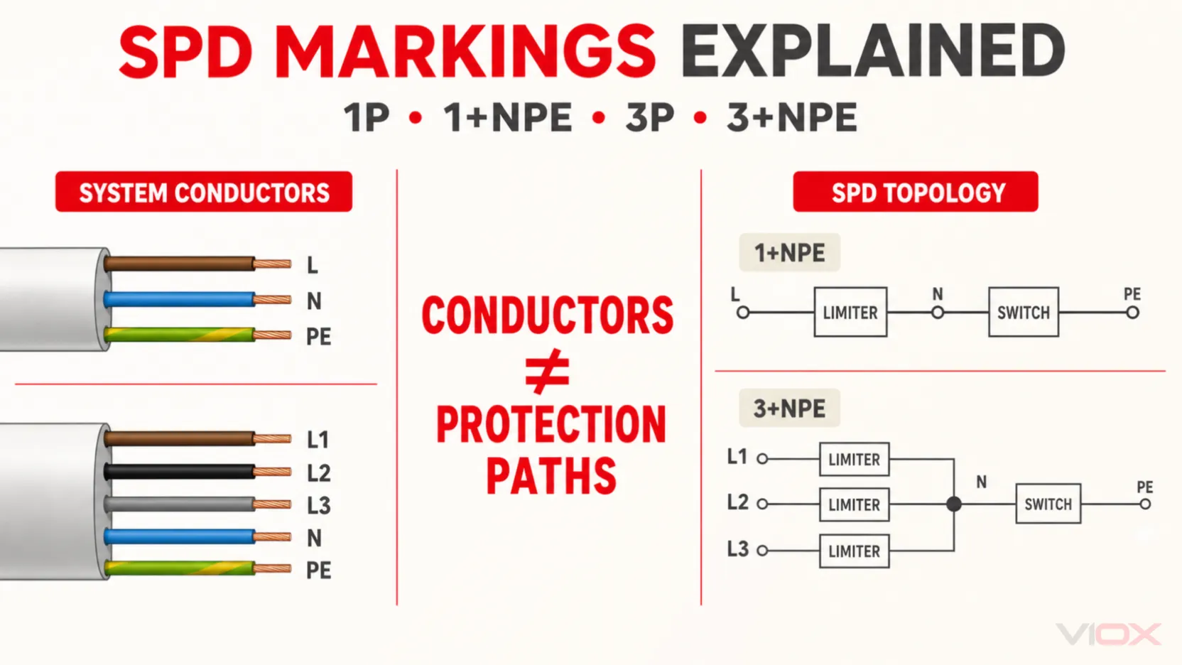
3P+N+PE and 3+NPE do not necessarily mean the same thing. In a cable schedule or single-line diagram, 3P+N+PE usually describes five conductors: three phases, neutral and protective earth. On a surge protective device (SPD), 3+NPE or 3+1 commonly describes an internal protection topology: three line-to-neutral protection paths plus one neutral-to-earth discharge path.
The same distinction applies to 1P+N+PE and 1+NPE. One describes the conductors in the circuit; the other commonly describes how surge-protection elements are connected. Because manufacturer abbreviations vary, the SPD circuit diagram and declared modes of protection always take priority over the short label.
Scope: This guide uses IEC-oriented terminology for low-voltage AC installations. UL 1449 product categories, North American service configurations and manufacturer-specific MCOV markings require a separate selection check. Photovoltaic DC, battery DC and specialized IT applications are outside the simple rules in this article.
Key Takeaways
1P+N+PEnormally describes one phase, neutral and protective earth;3P+N+PEnormally describes three phases, neutral and protective earth.1+NPEor1+1on an SPD commonly means one L-N protection path plus one N-PE element.3+NPEor3+1commonly means three L-N paths plus one N-PE element.1Pand3Pare not universal SPD circuit definitions. They may describe protected conductors, cartridges, poles or a manufacturer’s product family.- Earthing system alone is not enough. Selection also depends on system voltage, neutral availability, PE or PEN arrangement, installation position and required modes of protection.
- SPD topology, SPD Type and electrical ratings are separate decisions.
- Never select an SPD from a fixed kA, voltage or conductor-size rule without checking the applicable installation standard and exact manufacturer instructions.
Quick Comparison: What Do the Markings Mean?
| Marking | Where it is commonly seen | Usual meaning | What it does not prove |
|---|---|---|---|
1P |
Product catalog, panel schedule or single-phase equipment description | One phase or one protected pole/path, depending on context | It does not identify whether the SPD is connected L-N or L-PE |
1P+N+PE |
Cable schedule, connector description or wiring diagram | One phase, one neutral and one protective-earth conductor | It does not specify the SPD’s internal protection elements |
1+NPE, 1+1 |
SPD topology or product description | Commonly one L-N voltage-limiting path plus one N-PE discharge path | It does not by itself establish Type, voltage rating or discharge-current capability |
3P |
Product catalog or three-phase equipment description | Three phases or three protected paths, depending on context | It does not prove whether the reference is N, PE or PEN |
3P+N+PE |
Cable schedule or electrical system diagram | Three phases, neutral and PE: normally five conductors | It is not automatically the same as an SPD marked 3+1 |
3+NPE, 3+1 |
SPD topology or product description | Commonly three L-N paths plus one N-PE discharge path | It does not prove that the topology suits every TN-S, TT or IT installation |
The table is a decoding aid, not a replacement for the product schematic. Some manufacturers use 1N, 3N, 3P+N, 1+1, 3+1 or other abbreviations for similar commercial configurations. Confirm the terminals and internal diagram before procurement or installation.
3P+N+PE Meaning: A Conductor Description, Not an SPD Rating
In an electrical supply description, 3P+N+PE normally means:
3P: L1, L2 and L3;N: neutral;PE: protective earth.
This is normally a five-conductor arrangement. It tells the designer which conductors are present, but not how an SPD should be connected among them.
Likewise, 1P+N+PE normally means:
- one phase conductor;
- one neutral conductor;
- one protective-earth conductor.
That is normally a three-conductor single-phase circuit. It still does not tell you whether the intended SPD is 1+1, 2+0 or another manufacturer-defined configuration.
This distinction matters for search terms such as 3npe, 3ph+n+pe and 1/n/pe meaning. The letters may describe a supply, cable, connector, socket or SPD. Identify the object and inspect its diagram before applying an SPD topology rule.
What 1+NPE and 3+NPE Commonly Mean on an SPD
1+NPE or 1+1 topology
A typical single-phase 1+1 arrangement contains:
- one protection element between line and neutral; and
- one protection element between neutral and protective earth.
The L-N element is commonly voltage-limiting technology, while the N-PE element is commonly a voltage-switching device. This arrangement provides a direct path for limiting line-to-neutral differential voltage and a coordinated path from neutral to earth during the surge.
Do not describe this as “line, neutral and earth are all protected.” PE is not a load conductor that the SPD protects in the same way as a phase. It forms part of the surge-current discharge and equipotential-bonding path.
Generic concept:
L ───── [L-N protection element] ───── N
                                         |
                                 [N-PE element]
                                         |
                                        PE
3+NPE or 3+1 topology
A typical three-phase 3+1 arrangement contains:
- L1-N protection;
- L2-N protection;
- L3-N protection; and
- one N-PE discharge path.
Generic concept:
L1 ─── [protection element] ───┐
L2 ─── [protection element] ───┼── N ─── [N-PE element] ─── PE
L3 ─── [protection element] ───┘
ABB’s global SPD guide lists 1+1 and 3+1 as protected-line configurations and separately maps product arrangements to TN-C, TN-S and TT networks. That is a useful reminder that the number describes protection architecture—not a universal quality grade or surge-current rating.
The exact internal technology is manufacturer-specific. Verify the declared protection modes, temporary-overvoltage behavior and, where a voltage-switching element is used, the power-frequency follow-current capability.
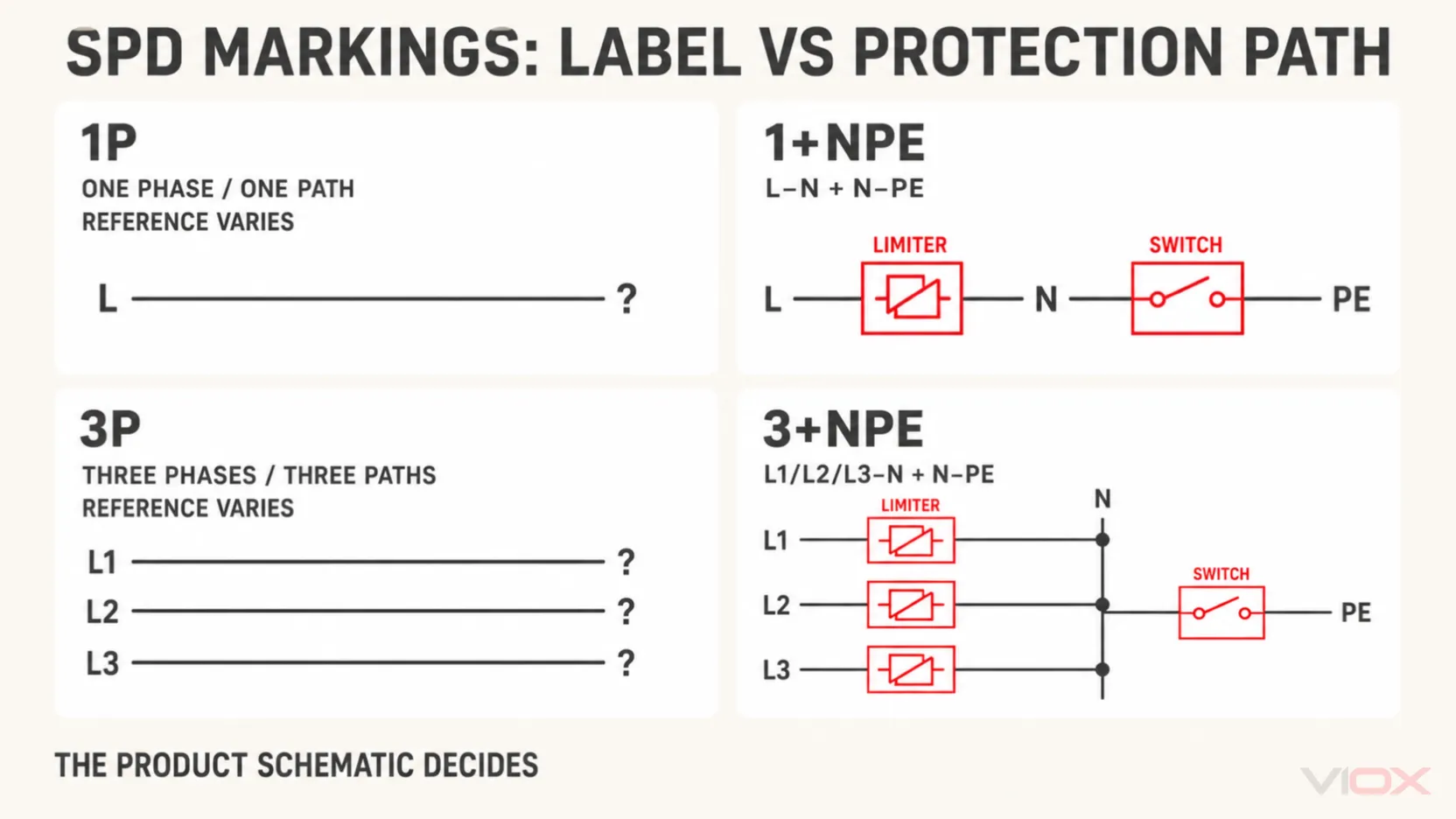
Why 1P and 3P Labels Are Not Enough
An SPD is connected in parallel with the supply; it does not normally switch the load conductors like a circuit breaker. As a result, “pole” can be less precise on an SPD than it is on an isolating or overcurrent device.
Depending on the manufacturer, 1P or 3P may refer to:
- the number of protected phase conductors;
- the number of cartridges;
- the number of protection paths;
- the DIN-rail module count;
- or a product-family description.
A three-pole label therefore does not prove whether the internal paths are L-N, L-PE or L-PEN. A four-module device does not automatically provide the same circuit as a 3+1 assembly. Use the product schematic to answer three questions:
- Which terminals are connected during a surge?
- Which protection modes are declared: L-N, L-PE, N-PE, L-PEN or L-L?
- Which voltage and current ratings apply to each mode or complete assembly?
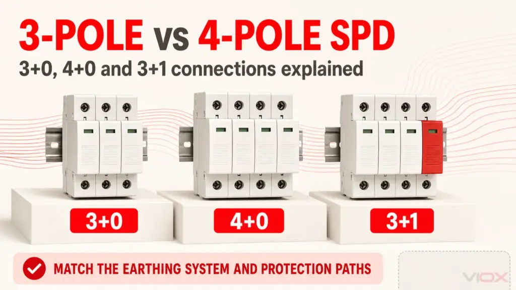
For the deeper three-phase comparison, see 3-Pole vs 4-Pole SPD: 3+0, 4+0 and 3+1 Connections.
Start Selection With the System at the Exact Installation Point
The correct first question is not “Is the supply single phase or three phase?” It is:
Which live, neutral and protective conductors exist where this SPD will be installed, and how are they earthed?
Record all of the following:
- nominal and maximum continuous system voltage;
- AC system configuration;
- whether neutral is distributed;
- whether the protective conductor is PE or combined PEN;
- whether the SPD is before or after a PEN separation point;
- the earthing system at that exact location;
- the installation level: origin, main board, sub-distribution or near the equipment;
- the required common-mode and differential-mode protection.
Earthing-system decision table
| System and location | Conductors at the SPD | Common topology starting point | Required caution |
|---|---|---|---|
| TN-C | L1/L2/L3 and PEN | Commonly 3+0, with phase-to-PEN paths | There is no separate N-PE path while N and PE remain combined |
| TN-C-S before PEN separation | L1/L2/L3 and PEN | Treat as the TN-C section | Identify the separation point rather than relying on the utility label alone |
| TN-C-S after PEN separation | L1/L2/L3, N and PE | Treat as TN-S; evaluate 3+1 or another permitted topology | N and PE must remain separate downstream of the defined bonding point |
| TN-S | L1/L2/L3, N and PE | 3+1 or another topology allowed by the design and local rules | Required common- and differential-mode protection must be defined |
| TT | L1/L2/L3, N and local PE | 3+1 is a common starting architecture | SPD/RCD position, N-PE element and failure behavior require verification |
| IT | Varies; neutral may be absent or distributed | Project-specific | First-fault voltage-to-earth and TOV conditions can invalidate a generic TN/TT rule |
ABB’s guidance illustrates different common-mode and differential-mode arrangements for TN-C, TN-S and TT systems rather than applying one configuration to all networks. The applicable national adoption of IEC 60364, the project single-line diagram and the SPD manufacturer’s instructions remain controlling.
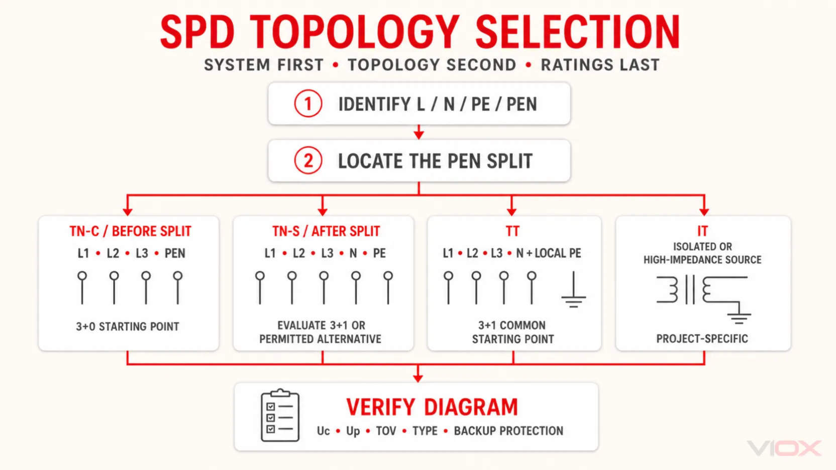
For an explanation of the network structures themselves, see TN vs TT vs IT Earthing Systems.
Typical Single-Phase and Three-Phase Wiring Concepts
These diagrams show topology only. They do not specify fusing, RCD position, conductor size, terminal torque or a complete compliant installation.
Single-phase 1+1 concept
Incoming L ───────┬──────────── Load L
                  │
              [L-N element]
                  │
Incoming N ───────┼──────────── Load N
                  │
              [N-PE element]
                  │
PE / bonding bar ─┴──────────── Equipment PE
This is a common concept for a single-phase circuit with separate N and PE. It must not be applied where the product voltage, earthing arrangement or local installation rules require a different configuration.
Three-phase 3+1 concept for suitable TN-S or TT applications
L1 ─────────────── [L1-N element] ──┐
L2 ─────────────── [L2-N element] ──┼── N
L3 ─────────────── [L3-N element] ──┘   │
                                        [N-PE element]
                                             │
                                             PE
This topology provides direct L-N paths and one N-PE path. It is commonly encountered in TN-S and TT product selections, but “TN-S” or “TT” alone does not complete the specification.
Three-phase 3+0 concept for TN-C
L1 ─────────────── [L1-PEN element] ──┐
L2 ─────────────── [L2-PEN element] ──┼── PEN
L3 ─────────────── [L3-PEN element] ──┘
At a TN-C point, neutral and protective functions are combined in PEN. Adding an independent N-PE path is not meaningful when separate N and PE conductors do not exist there.
SPD Topology Is Separate From Type 1, Type 2 and Type 3
1+1, 3+0 and 3+1 describe protection connections. Type 1, Type 2 and Type 3 describe test classification and application role. A 3+1 assembly can be Type 1, Type 2 or combined Type 1+2 if the manufacturer has designed and tested it accordingly.
| SPD classification | Principal IEC test quantity | Typical role in a coordinated concept |
|---|---|---|
| Type 1 / Class I tested | Impulse current Iimp, using a 10/350 μs current waveform |
Lightning-current protection where the risk assessment, external lightning protection system, incoming service or national rules require it |
| Type 2 / Class II tested | Nominal and maximum discharge current using an 8/20 μs current waveform | Distribution-level protection against induced lightning and switching transients |
| Type 3 / Class III tested | Combination-wave testing using a 1.2/50 μs voltage impulse and 8/20 μs current impulse | Supplementary protection close to sensitive equipment as part of coordinated protection |
Schneider Electric’s Type 1, Type 2 and Type 3 overview likewise distinguishes the 10/350 μs, 8/20 μs and combination-wave tests.
Do not convert this table into the rule “every service entrance needs a 100 kA Type 1 SPD.” SPD Type and discharge-current capability must follow the actual lightning risk, incoming services, installation design, national requirements and manufacturer coordination data.
For the complete classification topic, use SPD Type 1 vs Type 2 vs Type 3.
Ratings to Verify After Selecting the Topology
Correct topology is necessary, but it is only the first part of the specification.
| Parameter | What it tells you | Selection boundary |
|---|---|---|
Uc |
Maximum continuous operating voltage across the relevant SPD terminals | Must suit the actual system voltage, protection mode and earthing arrangement |
Up |
Declared voltage protection level under specified test conditions | Must be coordinated with equipment impulse withstand and installation voltage drop |
Iimp |
Impulse discharge-current rating associated with Type 1 testing | Relevant when lightning-current duty is required |
In |
Nominal discharge current, normally based on the 8/20 μs waveform | Used to compare declared repetitive discharge performance within the product standard |
Imax |
Maximum discharge current for a Type 2 SPD under stated 8/20 μs conditions | Not a universal indication of service life or installation suitability |
TOV |
Temporary-overvoltage withstand or behavior | Must reflect power-frequency overvoltages possible in the specific network and fault condition |
Ifi |
Follow-current interrupting capability where applicable | Important for voltage-switching elements that may conduct power-frequency follow current |
| Short-circuit rating or behavior | Ability to coordinate safely with prospective short-circuit current and disconnection | Verify terminology, declared value and required backup protective device from the exact datasheet |
There is no universal rule that 275 V Uc is correct for every 120/240 V or 230/400 V installation. Uc must be checked for the voltage appearing across each protection mode, including abnormal conditions considered by the applicable standard and manufacturer.
For more detail, see Uc vs Up on an SPD and Imax vs In for Surge Protective Devices.
Backup Protection and Connection Design
Follow the declared backup-protection arrangement
An SPD may include internal thermal disconnection, but external short-circuit protection may still be required. The permitted fuse or circuit-breaker arrangement depends on:
- the SPD design;
- available prospective short-circuit current;
- upstream overcurrent protection;
- manufacturer coordination tables;
- and the applicable installation standard.
Do not assign a fixed fuse or breaker to every SPD with the same Type label or discharge-current rating.
Keep connections short and direct
The inductive voltage developed along SPD connection conductors adds to the voltage seen by the protected equipment. Avoid long, looped or unnecessarily separated line and earth connections. Use the topology and routing method permitted by the manufacturer and local rules.
Size conductors from installation requirements—not a universal AWG table
Connection conductor cross-section depends on the SPD Type, product terminals, backup protection, fault-current conditions, installation standard and manufacturer instructions. A generic progression such as 12 AWG for one Type and 8 AWG for another should not be presented as a global requirement.
Coordinate protection stages
One SPD at the origin may not produce the required effective protection level at remote equipment. Cable length, the first SPD’s Up, the equipment impulse withstand and coordination with downstream SPDs all affect the result. Use the manufacturer’s coordination data rather than combining unrelated SPDs solely by Type label.
For practical layout risks, see SPD Installation Mistakes: Lead Length, Grounding and Wiring.
Eight-Step SPD Topology Selection Workflow
Step 1: Identify the object behind the label
Determine whether 3P+N+PE describes a cable, connector, power system or SPD. Do not interpret a conductor label as an internal protection circuit.
Step 2: Record the system voltage
Use the nominal voltage, expected continuous operating range and relevant fault/TOV conditions. Avoid selecting Uc from nominal voltage alone.
Step 3: Identify N, PE and PEN at the installation point
Verify whether neutral is distributed and whether protective and neutral functions are separate or combined. In TN-C-S, locate the PEN separation point.
Step 4: Confirm the earthing system
Identify TN-C, TN-S, TN-C-S, TT or IT from the actual single-line diagram. Do not infer it only from conductor colors or the number of terminals in a panel.
Step 5: Define the required protection modes
List the voltage stresses that must be limited: L-N, L-PE, N-PE, L-PEN and, where relevant, L-L. This step turns a vague “pole count” request into an engineering requirement.
Step 6: Select a topology starting point
Evaluate 1+1, 3+0, 3+1, 4+0 or another manufacturer-supported circuit. Confirm it from the schematic, not only the sales description.
Step 7: Select Type and electrical ratings
Determine Type 1, Type 2, Type 3 or a combined classification from the installation role and risk. Then verify Uc, Up, discharge-current ratings, TOV behavior, follow-current capability and short-circuit coordination.
Step 8: Verify installation details
Check backup protection, RCD relationship, connection routing, conductor cross-section, terminal capability, environmental conditions, indication and replacement method.
Common Selection Mistakes
Treating 3P+N+PE and 3+NPE as identical
The first commonly describes five system conductors. The second commonly describes an SPD topology. Confusing them can produce the wrong protection path.
Saying that earth is “protected” as another pole
PE is part of the protective bonding and surge-current path. It is not an ordinary active conductor to be described as protected in the same way as L or N.
Selecting from single phase versus three phase alone
Phase count does not reveal whether N exists, whether the reference conductor is PE or PEN, or whether the installation is before or after a PEN split.
Assuming every TN-S or TT system uses the same SPD
3+1 is a common architecture, but voltage, Type, protection mode, RCD position, TOV behavior, fault current and local rules still have to match.
Using one fixed Uc, kA rating or conductor size globally
These values are product- and system-dependent. A number that is appropriate for one voltage system or manufacturer series may be wrong for another.
Ignoring the circuit diagram
Commercial abbreviations are not fully standardized across manufacturers. The declared terminal diagram and modes of protection are the final evidence of the topology.
Specification Checklist
Before approving an SPD, record:
- system voltage and frequency;
- AC or DC application;
- conductor arrangement at the SPD location;
- TN-C, TN-S, TN-C-S, TT or IT system;
- position relative to the PEN split and residual current device;
- required L-N, L-PE, N-PE, L-PEN and L-L modes;
- selected topology and manufacturer circuit diagram;
- Type 1, Type 2, Type 3 or combined classification;
Uc,Up,Iimp,In,Imax, TOV and any applicableIfi;- prospective short-circuit current and declared SPD short-circuit behavior;
- required backup fuse or circuit breaker;
- connection routing and conductor requirements;
- applicable product certification and national installation rules.
Only after this checklist is complete should the designer compare product models. For product-family evaluation, review the VIOX surge protective device range and provide the single-line diagram and system data with the inquiry.
Frequently Asked Questions
What does 3P+N+PE mean?
In an electrical system, cable or connector description, 3P+N+PE normally means three phase conductors, one neutral conductor and one protective-earth conductor. It normally describes five conductors. It does not by itself specify the internal topology of an SPD.
Is 3P+N+PE the same as 3+NPE on an SPD?
No. 3P+N+PE usually describes the conductors present in the system. 3+NPE or 3+1 commonly describes three L-N protection paths plus one N-PE protection element inside an SPD. Always verify the product schematic.
What does 1P+N+PE mean?
It normally means one phase, one neutral and one protective-earth conductor. This describes a typical three-conductor single-phase circuit, not necessarily a 1+1 SPD topology.
What is a 1+NPE SPD?
A 1+NPE or 1+1 SPD commonly contains one L-N voltage-limiting path and one N-PE discharge path. Exact technology, ratings and permitted systems depend on the product.
What is a 3+NPE SPD?
A 3+NPE or 3+1 SPD commonly contains three L-N protection paths and one N-PE path. It is frequently used as a starting topology for suitable three-phase TN-S and TT applications, subject to the exact network and installation rules.
Does NPE mean the earth conductor carries normal current?
No. PE should not carry normal load current. The N-PE element provides a surge-current path under transient conditions and must behave according to its declared design and system requirements.
Is a 3+1 SPD always better than a 3+0 SPD?
No. They fit different conductor and earthing arrangements. A TN-C point with PEN commonly leads to a 3+0 architecture, while a system with separate N and PE may require 3+1 or another permitted topology.
Can I select an SPD only from the number of poles?
No. Pole count does not fully define the protection modes, Type, voltage rating, discharge-current rating, TOV behavior or short-circuit coordination. Inspect the schematic and datasheet.
What is the difference between SPD topology and SPD Type?
Topology describes how protection elements connect among L, N, PE or PEN. Type 1, Type 2 and Type 3 describe test classification and application role. They are independent selection dimensions.
Conclusion
The safest way to interpret 1P, 1+NPE, 3P and 3+NPE is to separate conductor notation from SPD topology. 3P+N+PE normally tells you that three phases, neutral and protective earth are present. 3+NPE or 3+1 commonly tells you how four surge-protection paths are arranged.
Neither label completes the specification. Correct SPD selection requires the system voltage, earthing arrangement, N/PE/PEN configuration, installation position, protection modes, SPD Type, electrical ratings, backup protection and manufacturer wiring instructions. When the abbreviation and circuit diagram appear to disagree, trust the verified circuit diagram and request clarification before installation.