On this page
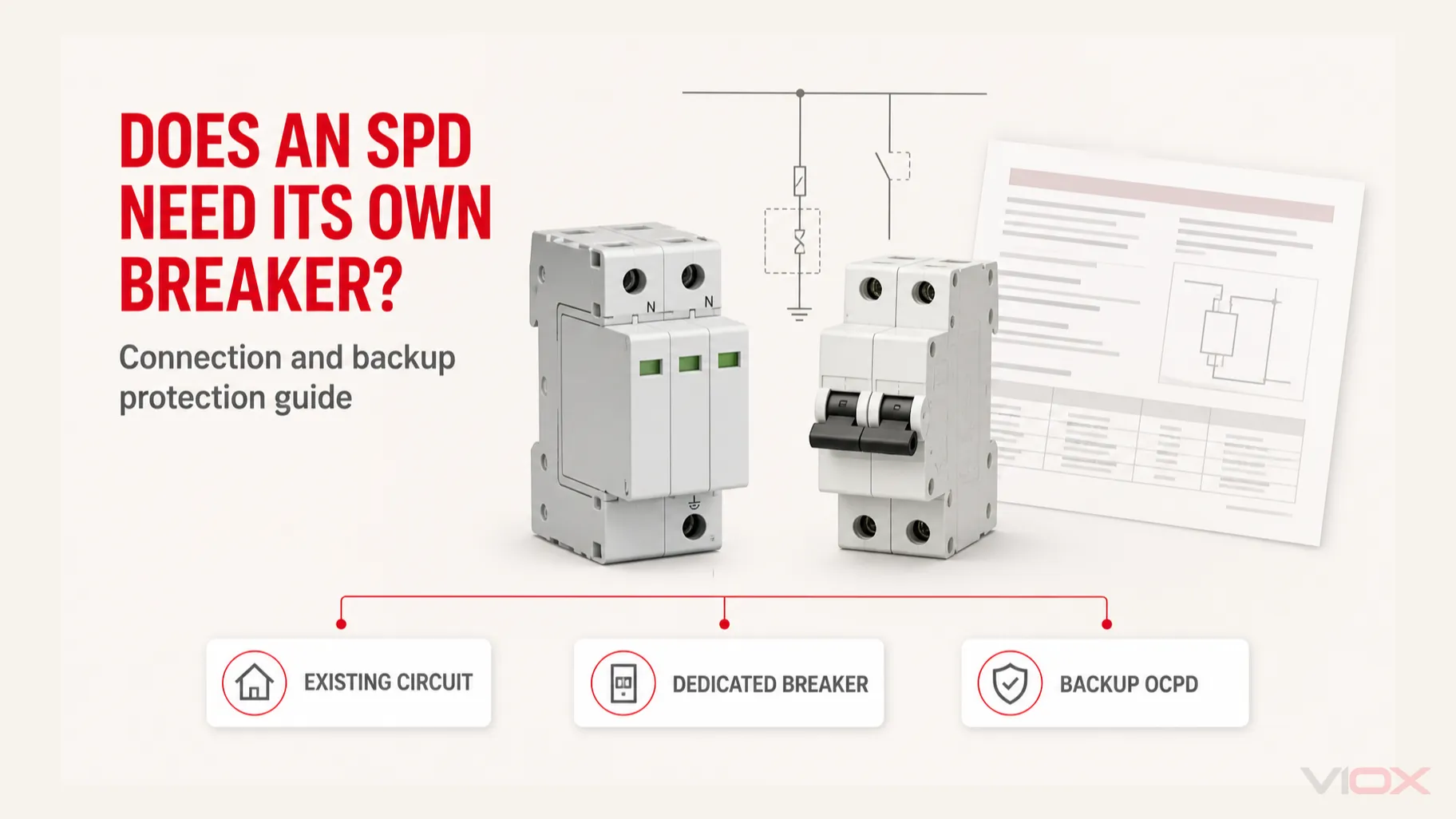
Sometimes—but only when the exact surge protective device (SPD) instructions, the existing overcurrent protective device (OCPD), the conductor and terminal ratings, and the applicable installation rules all permit it. A dedicated breaker is often the clearest way to connect and isolate a panel-mounted SPD, but it is not a universal requirement.
For an IEC-oriented DIN-rail SPD, the question is often different: does the upstream fuse or breaker already satisfy the manufacturer’s maximum backup-protection condition, or must a separate backup fuse or breaker be added? That decision cannot be made from SPD Type or surge-current rating alone.
Key Takeaways
- A breaker used as the SPD’s connection point is not automatically the same as the manufacturer’s required backup OCPD.
- The SPD’s internal thermal disconnector protects against abnormal heating or end-of-life behavior; it does not automatically provide branch-conductor overcurrent protection.
- A suitable existing branch circuit is permitted for some products, but only when the exact instructions and all conductor, terminal, panel, and OCPD conditions are met.
- Never use a universal “SPD breaker size.” The required device, rating, poles, characteristic, and short-circuit coordination are model- and installation-specific.
- Panel work and SPD connections should be designed and completed by qualified personnel under the applicable local rules.
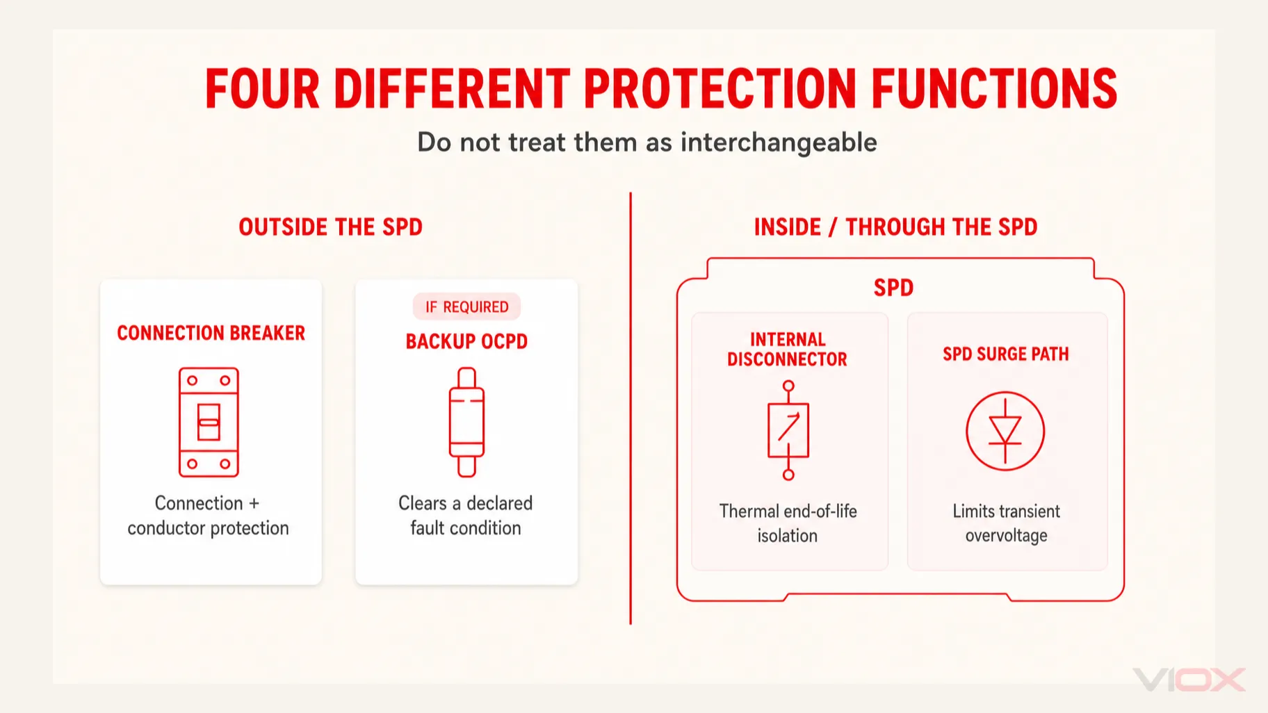
First Separate the Three Meanings of “SPD Breaker”
The question becomes much easier once three different functions are separated.
| Function | What it does | What must prove suitability |
|---|---|---|
| Connection breaker or branch OCPD | Provides a connection point and may protect the SPD branch conductors; it can also provide isolation | SPD instructions, conductor ampacity, terminal ratings, panel compatibility, and local installation rules |
| External backup fuse or breaker | Clears a fault involving the SPD or its branch when the upstream protection alone does not meet the product’s declared condition | Exact manufacturer backup-protection table, short-circuit declaration, upstream OCPD, and coordination study |
| Internal SPD disconnector | Disconnects a failed or overheated protective component inside the SPD | Product construction and its evaluated or declared internal protection—not an assumption about external conductors |
This distinction matters because an SPD normally operates as a shunt device: it draws negligible current in normal service and carries surge current only during a transient. Its external OCPD is therefore not selected like the breaker for a continuous load, and it is not expected to interrupt the surge before the SPD operates.
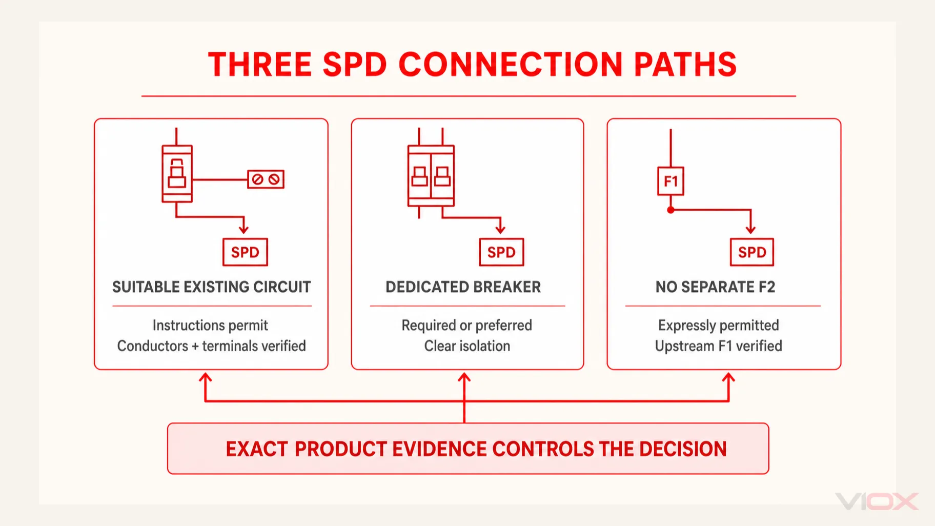
The Three Acceptable Decision Paths
| Proposed path | It may be acceptable when | Reject or redesign when |
|---|---|---|
| Suitable existing branch circuit | The exact SPD instructions allow it; the existing OCPD and circuit remain suitable; SPD conductors have adequate ampacity; every termination is authorized; isolation and loss-of-protection consequences are acceptable | The instructions require a dedicated circuit; the terminal is not identified for the conductors proposed; conductor protection is inadequate; opening the shared breaker would unknowingly remove critical surge protection |
| Dedicated breaker or fuse | The product calls for it, a clear isolation point is required, a separate branch simplifies conductor protection, or the panel arrangement supports a shorter and more direct connection | The selected OCPD conflicts with the product’s tested or declared configuration, has inadequate interrupting capability, or creates excessive connection length without an engineered solution |
| No separate branch OCPD | The exact Type 1, integral, bus-connected, or IEC branch arrangement expressly permits it and upstream protection plus conductor rules satisfy all stated conditions | The decision is based only on “Type 1,” an internal thermal disconnector, or a high SCCR/Isccr; external conductors or the assembly still require protection |
The correct output is not merely “yes” or “no.” It is a documented path tied to one exact SPD model, one distribution assembly, and one upstream protective arrangement.
Seven Checks Before Reusing an Existing Breaker
1. Identify the SPD Type and permitted connection location
Type changes where a device may be installed, but it does not complete the breaker decision. In North American terminology, a Type 1 SPD can be installed on either side of the service overcurrent disconnect within its permitted application; a Type 2 SPD is installed on the load side. Eaton’s published SPD guidance notes that Type 1 devices may be applied without a dedicated fuse or breaker for the SPD function, while Type 2 devices may or may not require one. The exact product instructions and installation rules remain controlling.
That does not mean every Type 1 device may be connected directly to any bus. The conductors, enclosure or assembly, disconnecting method, and exact installation instructions still control. See the Type 1 vs Type 2 vs Type 3 SPD guide for classification; keep the present decision focused on the connection and backup protection.
2. Read the exact connection diagram and OCPD statement
Do not approve the connection from a catalog headline or a similar model’s manual. Obtain the current instruction sheet for the exact catalog number and record:
- whether a dedicated or suitable existing branch circuit is allowed;
- required or maximum OCPD type and rating;
- permitted poles and system configurations;
- conductor range, insulation rating, and terminal torque;
- whether a backup fuse or breaker was part of the declared short-circuit condition;
- whether an integral disconnector or fuse changes the external requirements.
For example, Schneider Electric states for one externally mounted SPD family that the assembly can use either a dedicated branch circuit or a suitable existing branch circuit. That is evidence for that named product family—not a universal rule for every whole-building SPD.
3. Verify the existing breaker and panel as an assembly
The proposed breaker must be permitted for the panelboard or switchboard and suitable for the system voltage, poles, interrupting duty, and application. An available empty breaker is not automatically a compatible one.
If the plan places more than one conductor in a breaker terminal, the terminal must be specifically identified for that number, material, and size of conductors. Do not treat “sharing a breaker” as permission to double-tap a terminal that is marked for one conductor. A listed distribution block, an approved pigtail arrangement, or another method may be required, but the exact solution belongs in the panel and product documentation—not in a generic SPD article.
4. Check conductor protection and termination limits
When a manufacturer permits an existing branch circuit, the SPD conductors still need adequate ampacity for the existing OCPD and must fit every terminal used. Schneider’s guidance for a particular externally mounted assembly, for example, requires the SPD conductors on an existing branch circuit to have ampacity not less than the OCPD setting.
This is why a generic breaker-size table is unsafe. Two SPDs with similar surge ratings can use different lead sizes, terminal ranges, OCPD conditions, and listing or declaration details.
5. Compare available fault current with SCCR or Isccr
For UL-oriented equipment, the SPD’s short-circuit current rating (SCCR) must not be lower than the available fault current at its connection point. Eaton’s Bussmann application guide also notes that when a specific OCPD was used to obtain the SPD’s UL short-circuit condition, the installed OCPD must match the documented type and rating.
For IEC products, verify the applicable short-circuit withstand/current declaration, often shown as Isccr, together with the manufacturer’s stated backup protective device. SCCR and Isccr are not surge-current ratings: do not substitute In, Imax, or Iimp for short-circuit coordination.
The SPD datasheet guide explains these declarations and the other ratings that must be checked before procurement.
6. Decide whether shared isolation is operationally acceptable
If the SPD shares an existing branch OCPD, opening or tripping that device may remove both the load and its surge protection. Conversely, an SPD fault could interrupt the shared circuit. That may be unacceptable for a critical control panel, process line, data system, fire/life-safety interface, or other installation where protection status must be independently monitored and restored.
A dedicated breaker can make isolation and maintenance clearer, but this is an operational advantage—not proof that one is always required.
7. Protect the installation performance
Adding an OCPD or moving the SPD to a convenient spare circuit can increase lead length and inductance. The resulting installation can have a higher let-through voltage than the device-only test value suggests. Keep connections short and direct within the product instructions and applicable rules; avoid loops and unnecessary bends.
The SPD wiring guide owns the full phase, neutral, PE, backup-protection, lead-routing, and commissioning workflow. This page determines which connection path should enter that design.
When a Dedicated Breaker Is the Better Decision
Use a dedicated breaker or fuse when the exact product instructions require it. It is also commonly preferred when it provides:
- unambiguous conductor protection;
- a clearly labeled isolation point for inspection or replacement;
- independent service continuity for other circuits;
- a practical short and direct SPD connection;
- a documented OCPD that matches the product’s tested or declared condition;
- cleaner panel schedules and maintenance records.
Do not choose its rating from the SPD’s kA surge-current capacity. The branch or backup OCPD must be selected from the manufacturer instructions, conductor requirements, fault-current study, and applicable installation rules.
A manufacturer-specific number can be useful evidence. Schneider, for example, recommends a 20 A or 30 A two-pole breaker for certain HEPD models. That number must not be copied to a VIOX DIN-rail SPD, an industrial switchboard SPD, or even another Schneider family without its own instructions.
IEC Installations: Compare Upstream F1 with the Declared Backup Limit
In many IEC-oriented shunt-connected SPD applications, the design uses this logic:
- Identify the upstream system fuse or breaker, F1.
- Find the exact SPD manufacturer’s maximum permissible backup fuse or breaker and any required device class or characteristic.
- If F1 satisfies the manufacturer’s stated condition, a separate branch backup device F2 may be unnecessary for that exact arrangement.
- If F1 exceeds the permitted limit—or the instructions otherwise require a branch device—select F2 according to the manufacturer data, fault level, conductor protection, selectivity, and impulse-current withstand.
Phoenix Contact illustrates this product-specific approach in its backup-fuse guidance: whether F2 is needed depends on F1, the selected SPD, and the manufacturer’s maximum backup-fuse value. The guide also warns that an added fuse that lacks sufficient impulse withstand can open during a surge and leave the installation unprotected.
This is the correct level of generalization. It explains the decision without turning one manufacturer’s fuse values into an industry-wide table. IEC 61643-12:2020 covers AC SPD selection and application principles and includes disconnecting-device information; the exact product declaration completes the design.
Two Bounded Examples
Example A: externally mounted panel SPD in North America
The manufacturer instructions permit either a dedicated branch circuit or a suitable existing one. Before reusing an existing breaker, the designer verifies that:
- the SPD Type and installation location are permitted;
- the breaker and panel are compatible;
- the existing OCPD does not exceed the ampacity of the SPD conductors;
- the proposed termination is identified for all conductors used;
- available fault current does not exceed the SPD’s SCCR under the documented OCPD condition;
- sharing the circuit will not create an unacceptable loss-of-protection condition;
- connection length remains within the manufacturer’s installation guidance.
If one check fails, the answer is not “use a larger breaker.” Use a dedicated compatible path or select a different SPD/assembly arrangement.
Example B: DIN-rail Type 2 SPD in an industrial IEC panel
The datasheet states a maximum permissible upstream backup fuse and an Isccr condition. The project compares the installed F1 with that declaration. If F1 is within the permitted condition and the manufacturer allows omission of F2, the SPD branch may not need a separate backup fuse. If F1 exceeds the limit, F2 is required and must match the declared device type/rating while coordinating with fault current, conductors, and surge impulse duty.
Neither example produces a universal breaker size. Both produce a traceable approval record.
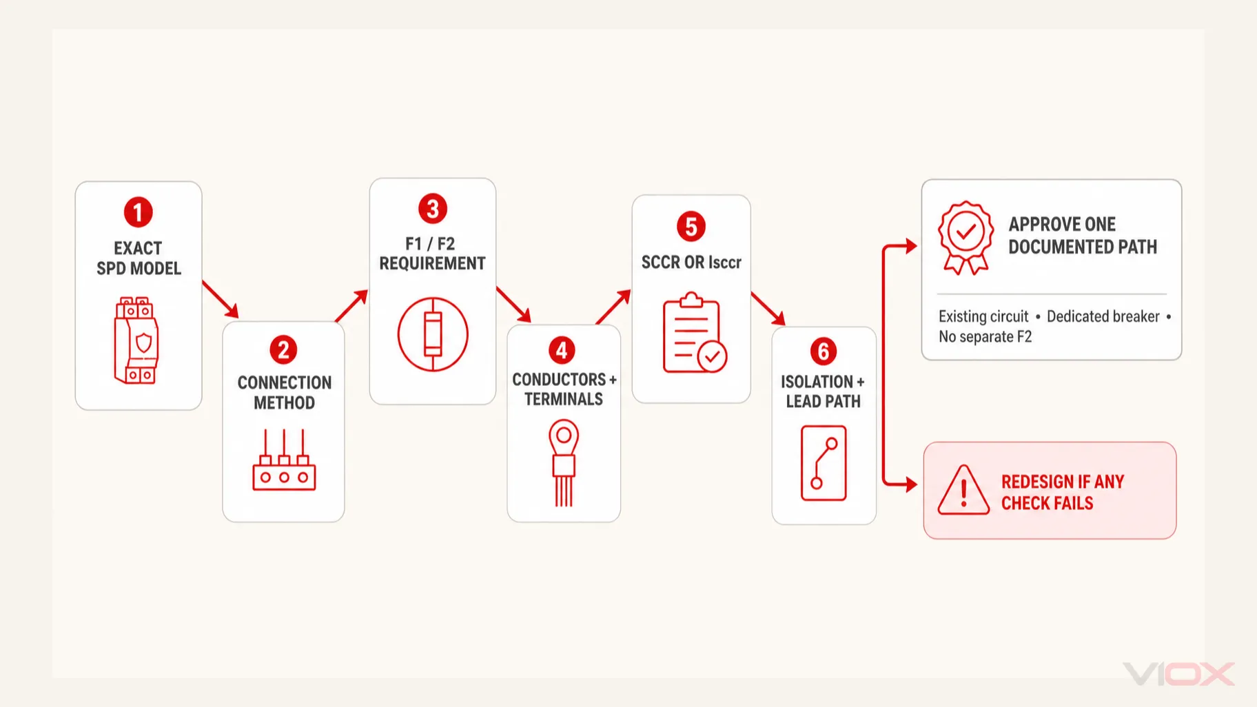
SPD Breaker and Backup-Protection Approval Checklist
| Required evidence | Acceptance question | Record |
|---|---|---|
| Exact SPD catalog number | Is the instruction sheet for this precise model and revision? | Model/revision |
| System and SPD Type | Is the connection location permitted? | Type and location |
| Manufacturer connection method | Existing branch, dedicated branch, direct/integral, or another declared arrangement? | Selected path |
| Upstream OCPD F1 | What device, rating, characteristic/class, poles, voltage, and interrupting rating are installed? | F1 details |
| Required backup OCPD F2 | Is F2 required, optional, integrated, or expressly unnecessary under stated conditions? | F2 decision |
| Conductors and terminals | Are ampacity, material, size, temperature rating, quantity per terminal, and torque all permitted? | Verified values |
| Fault-current coordination | Is available fault current within SCCR or the applicable IEC declaration such as Isccr? | Study and declaration |
| Panel or assembly compatibility | Are the breaker, accessories, and termination method authorized? | Manufacturer evidence |
| Isolation and monitoring | Can the SPD be safely isolated, and will loss of protection be visible or remotely indicated? | Operating method |
| Connection path | Are leads short, direct, and compliant with the exact instructions? | Drawing/reference |
| Applicable rules | Has the design been checked for the project jurisdiction and assembly standard? | Reviewer/approval |
Do not release the installation or purchase order while any required row is “assumed.”
Frequently Asked Questions
Does a whole-house surge protector need its own breaker?
Not always. Many panel-mounted Type 2 products use a dedicated two-pole breaker, but some exact products permit a suitable existing branch circuit or another listed connection. Follow the specific SPD and panel instructions rather than a universal rule.
Can an SPD be connected to the main breaker?
Do not place SPD conductors under main-breaker terminals unless the complete assembly and product documentation expressly permit that connection. Type 1 suitability does not by itself authorize an improvised main-terminal tap. Service-side work may also require utility coordination and jurisdiction-specific approval.
Can a Type 1 SPD be installed without a dedicated breaker?
Some Type 1 SPDs are evaluated or declared for installation without a dedicated fuse or breaker. External conductors and the distribution assembly may still require an approved protection or tap arrangement. Verify the exact instructions, SCCR condition, and applicable rules.
What size breaker should I use for an SPD?
Use the breaker or fuse type and rating stated for the exact SPD and installation. If the instructions provide only a maximum value, the final selection must also protect the conductors, satisfy fault-current and coordination requirements, and withstand the relevant surge impulse. SPD kA ratings do not directly determine breaker amperage.
Can two wires be connected to one breaker for an SPD?
Only when the breaker terminal is specifically identified for the number, material, and size of conductors proposed and the SPD instructions allow the circuit arrangement. Otherwise use an approved connection method designed for the assembly; do not improvise a double tap.
Does the breaker protect connected equipment from the surge?
No. The SPD limits transient overvoltage and diverts surge current. The breaker or fuse provides overcurrent protection and isolation according to its design. These devices perform different, coordinated functions.
Final Decision
An SPD may use an existing breaker only after the exact product and installation evidence proves that path suitable. Choose a dedicated breaker when the instructions require one or when it provides the necessary conductor protection, isolation, and operating clarity. For IEC designs, compare upstream F1 with the manufacturer’s maximum backup-protection declaration before deciding whether F2 is required.
For an industrial SPD quotation, provide VIOX with the single-line diagram, system voltage and earthing arrangement, SPD Type, available fault current, upstream OCPD, proposed connection method, required backup protection, and panel constraints. Review VIOX surge protective devices only after those inputs are defined.
Technical References
- IEC 61643-12:2020 — AC power SPD selection and application principles
- IEC 61643-11:2025 — SPDs connected to AC low-voltage power systems
- IEC 61643-01:2024 — General requirements and test methods
- UL Solutions — Molded Case Circuit Breaker Marking and Application Guide
- Eaton Bussmann — UL and data signal SPD application guide
- Eaton — Surge protection FAQ and Type 1/Type 2 application boundary
- Schneider Electric — connecting an externally mounted SPD to a panel
- Schneider Electric — HEPD breaker example
- Phoenix Contact — selecting the right SPD backup fuse
This article supports specification and design review. It is not an energized-work or DIY panel-installation procedure. Final work must follow the exact equipment instructions, the applicable installation rules, and qualified engineering or electrical review.