On this page
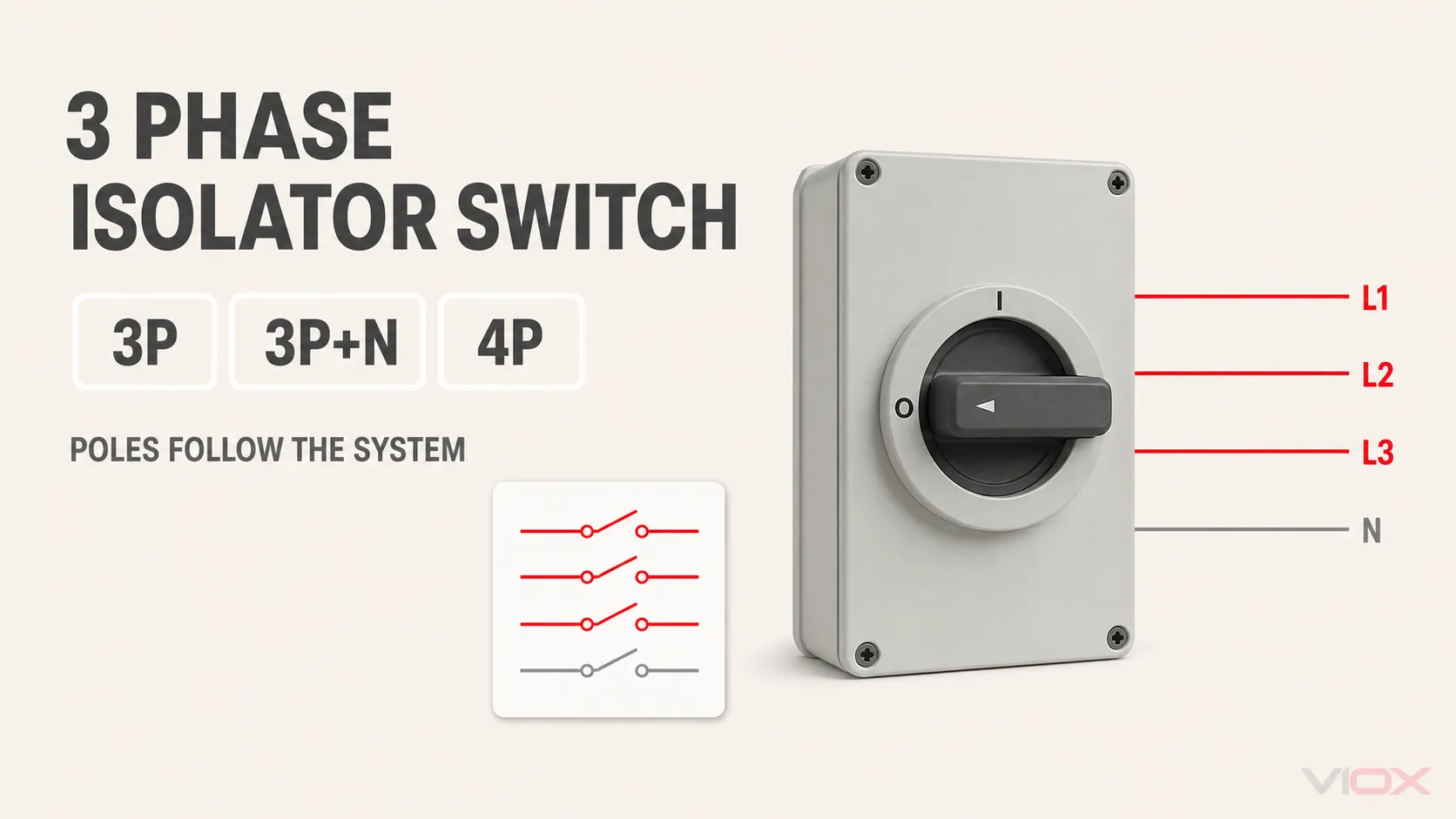
A 3 phase isolator switch operates multiple poles together to separate a three-phase circuit from its source. Use a 3-pole arrangement when the design requires L1, L2, and L3 to be disconnected while the neutral is absent or remains connected. Consider 3P+N or 4P only when the system design and applicable rules require the neutral to be switched.
Pole count does not prove load-breaking capability. A disconnector provides isolation but may not be intended to open normal load current. A switch-disconnector provides isolation plus its declared making and breaking duty. Before choosing either device, verify its rated operational voltage (Ue), rated operational current (Ie), utilization category, contact diagram, neutral-pole behavior, short-circuit coordination, and installation conditions.
| First decision | What to verify |
|---|---|
| Isolation only or normal load switching? | Disconnector versus switch-disconnector function |
| Three phases only or three phases plus neutral? | 3P, 3P+N, or 4P contact arrangement |
| May the neutral be interrupted? | Earthing system, source architecture, local rules, and equipment requirements |
| Is there a PEN conductor? | Do not place the PEN in the switching path under the applicable TN-C rules |
| Motor, mixed, or resistive load? | Ie at Ue under the required utilization category |
| Can the switch clear a fault? | No assumption: coordinate it with the specified upstream short-circuit protective device |
If you need a general introduction before applying these decisions to a three-phase system, start with what an isolator switch is.
Where a 3 Phase Isolator Sits in the System
The system boundary is more important than the handle shape. In a typical low-voltage circuit, the device is placed between a source-side protective arrangement and the equipment or distribution section that must be isolated.
Three-phase source
        │
Upstream fuse or circuit breaker (fault protection)
        │
3P / 3P+N / 4P disconnector or switch-disconnector
        │
Three-phase load or downstream distribution

Protective earth (PE): continuous protective path; not a switched pole
Neutral (N): switched only when the system design and applicable rules require it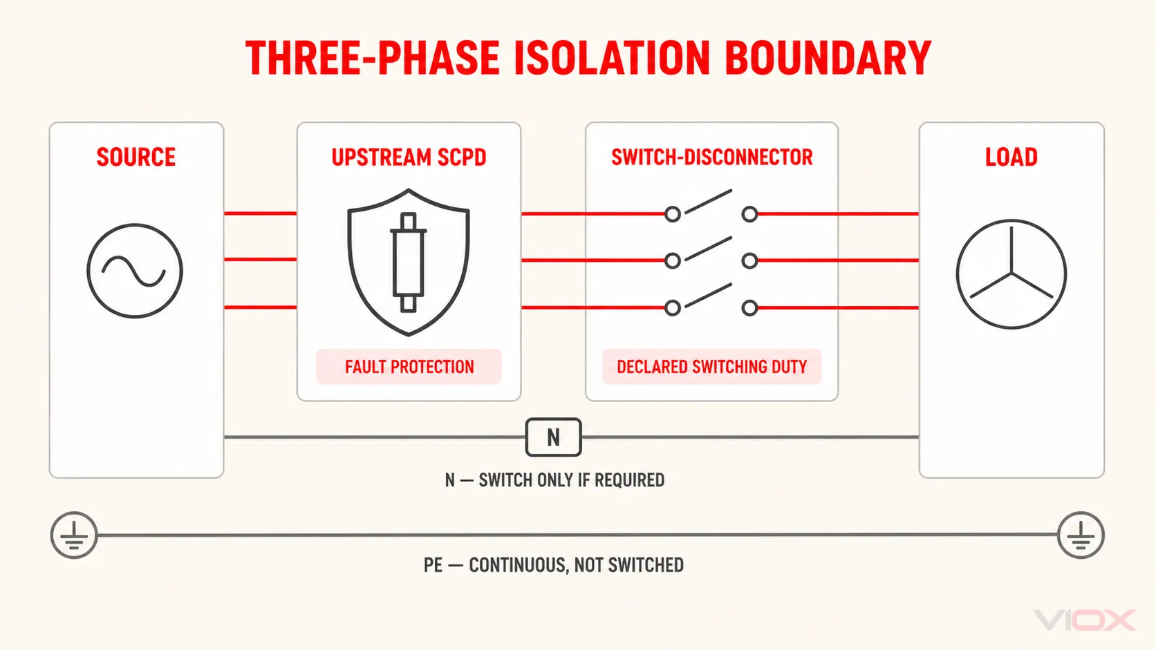
This is a functional diagram, not a terminal-level wiring instruction. Terminal locations, line/load orientation, pole-series arrangements, auxiliary contacts, and tightening requirements must come from the exact product instructions and approved project drawing.
The isolating device does not replace overcurrent or short-circuit protection. Its upstream short-circuit protective device (SCPD) must be selected and coordinated for the circuit and any conditional short-circuit declaration. The separate circuit breaker vs isolator switch guide explains that protection boundary in more detail.
Disconnector or Switch-Disconnector?
“Three phase isolator switch” is a market term, not enough information for engineering selection. Convert it into the required function.
| Device function | Isolation function | Normal load switching | Fault interruption |
|---|---|---|---|
| Disconnector | Yes, within its declared isolation conditions | Do not assume; verify the declaration | No automatic overcurrent interruption |
| Switch-disconnector | Yes | Yes, within its Ue, Ie, utilization category, and operating conditions | No automatic overcurrent interruption |
| Fuse switch-disconnector | Isolation and switching as declared | As declared for the complete arrangement | Integrated fuses may provide protection when correctly selected and coordinated |
IEC 60947-3:2020+AMD1:2025 covers switches, disconnectors, switch-disconnectors, and fuse-combination units within its stated low-voltage scope. That product-standard family distinguishes isolation, switching, withstand, making, and protection functions; the word “isolator” alone does not establish all of them.
A four-pole product can be a load-switching device. For example, Hager publishes a specific four-pole load-break switch with declared AC-21, AC-22, and AC-23 operational ratings. This example demonstrates the principle only: four poles does not mean off-load only. It does not transfer that model’s ratings to another product.
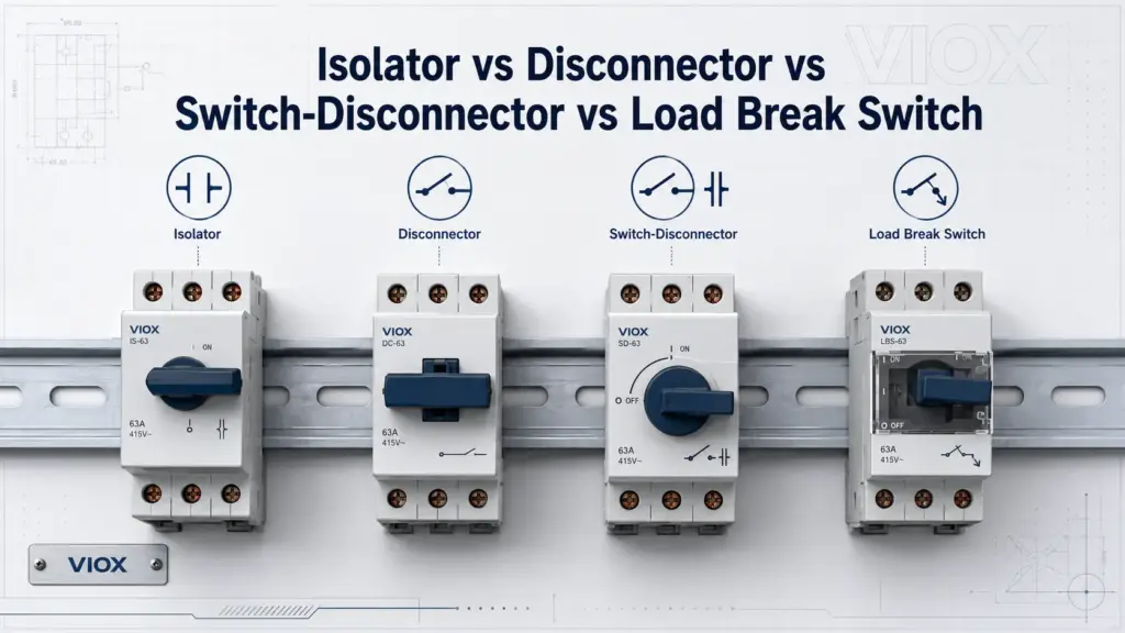
For a deeper terminology map, see isolator vs disconnector vs switch-disconnector.
3-Pole vs 4-Pole Isolator Switch: Should the Neutral Be Switched?
Do not begin with “3P or 4P?” Begin with the conductors and sources in the circuit. Determine whether a neutral exists, whether it is N or PEN, whether alternate sources can keep it energized or establish another reference, and what the applicable rules require.
| Arrangement | Conductors controlled | Where it may fit | What must be verified |
|---|---|---|---|
| 3P | L1, L2, L3 | Three-wire motor or other circuit with no distributed neutral; systems where the neutral is not required to be switched | Earthing system, absence or treatment of neutral, control-power path, and local rules |
| 3P+N | Three phase poles plus a dedicated N pole | Four-wire systems requiring coordinated neutral switching | N marking, neutral-pole rating, contact sequence, and manufacturer diagram |
| 4P | Four operated poles | Three-phase four-wire distribution, transfer, or other architectures requiring all four declared poles | Function of the fourth pole, equal or reduced rating, contact sequence, diagram, and applicable rules |
| Application-specific 4P DC | DC conductors or series contact paths | Some photovoltaic, battery, or DC distribution products | Explicit DC Ue, Ie, utilization category, polarity, series path, and manufacturer instructions |
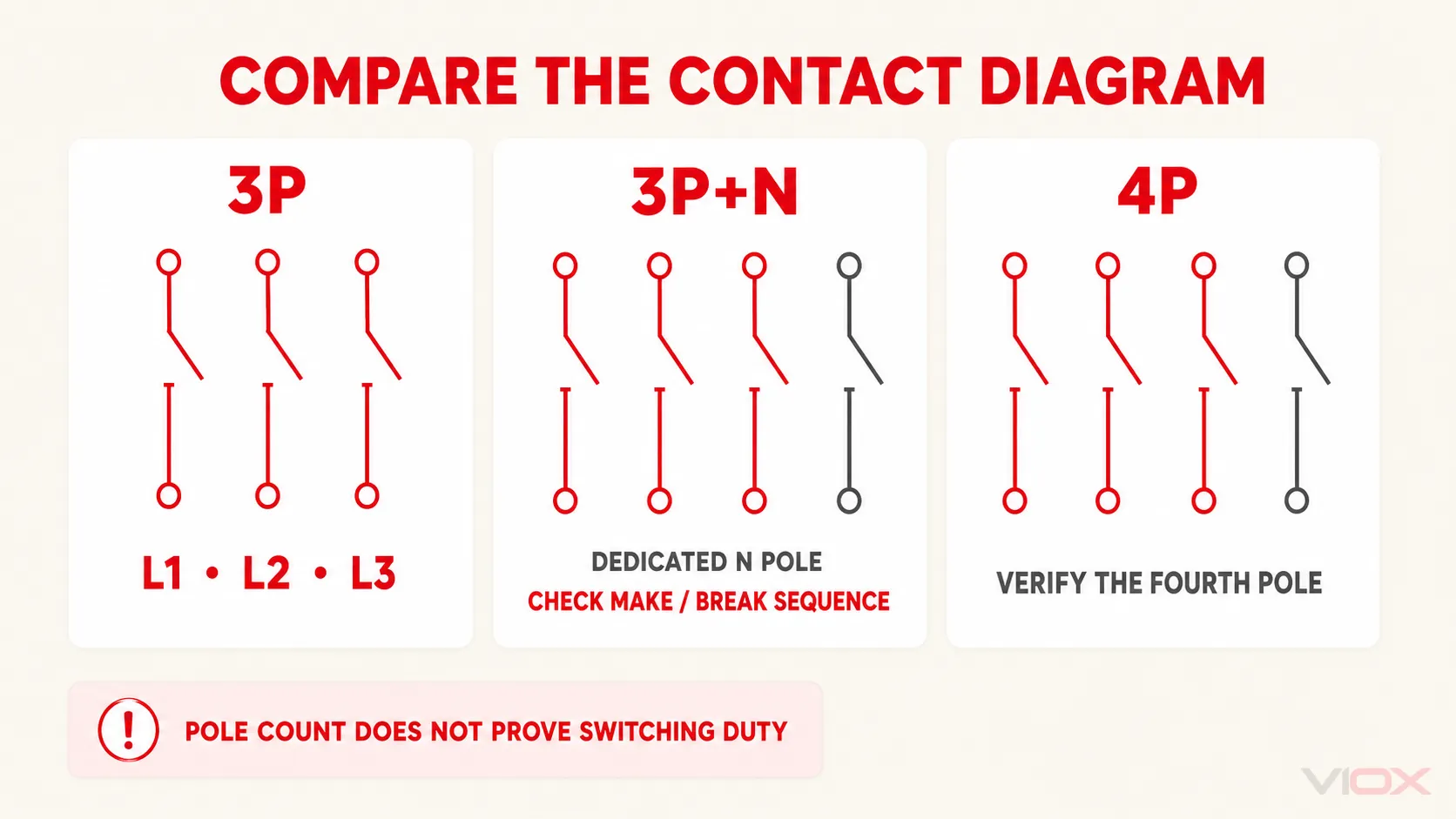
3P+N Is Not Automatically the Same as 4P
The fourth path may not behave like a phase pole. It can be identified as a neutral pole and may have a defined operating sequence. Schneider Electric’s model-specific 3P+N switch-disconnector guidance describes an N pole that closes before and opens after the phase poles to reduce the risk of a floating neutral in that product arrangement.
That behavior must not be assumed for every 3P+N or 4P device. Check:
- the product’s contact diagram;
- whether the fourth pole is marked N;
- whether it closes first and opens last, or operates simultaneously;
- the operational and thermal rating of the neutral pole;
- whether the accessory and handle operate all required poles together; and
- the manufacturer’s permitted connection arrangement.
Neutral Switching Depends on the System
There is no safe global rule that every three-phase circuit must use four-pole isolation. Schneider Electric’s engineering discussion of three- versus four-pole switching illustrates several important boundaries in a Dutch NEN 1010 context:
- a PEN conductor in the cited TN-C arrangement must not be interrupted;
- some TN-S situations may use three-pole separation, while others require the neutral to be included;
- TT circuits and downstream distribution can impose different neutral requirements; and
- a UPS or another source architecture can make neutral treatment more complex than simply adding a fourth pole.
These examples are not a global wiring rule. They show why the designer must identify the earthing arrangement, every source, the neutral reference, and the applicable national rules before specifying the pole arrangement.
Seven Questions for the 3P/3P+N/4P Decision
Use this sequence before comparing product codes.
- Does the load or downstream section use a neutral? A three-wire motor circuit and a four-wire distribution circuit do not have the same conductor set.
- Is the conductor a neutral (N) or a combined protective and neutral conductor (PEN)? Do not treat these as interchangeable.
- What does the applicable installation rule require or prohibit? Record the jurisdiction and the specific project interpretation.
- Are there alternate sources or parallel paths? Check generators, uninterruptible power supplies (UPS), automatic transfer switches (ATS), inverters, and backfeed paths.
- Is the proposed device 3P+N or 4P? Read the marking and contact diagram rather than relying on the catalog title.
- How does the neutral pole operate? Verify first-make/last-break or other declared sequencing, plus the fourth-pole rating.
- Does the device have the required switching duty? Pole count does not replace the Ue, Ie, utilization-category, and coordination checks.
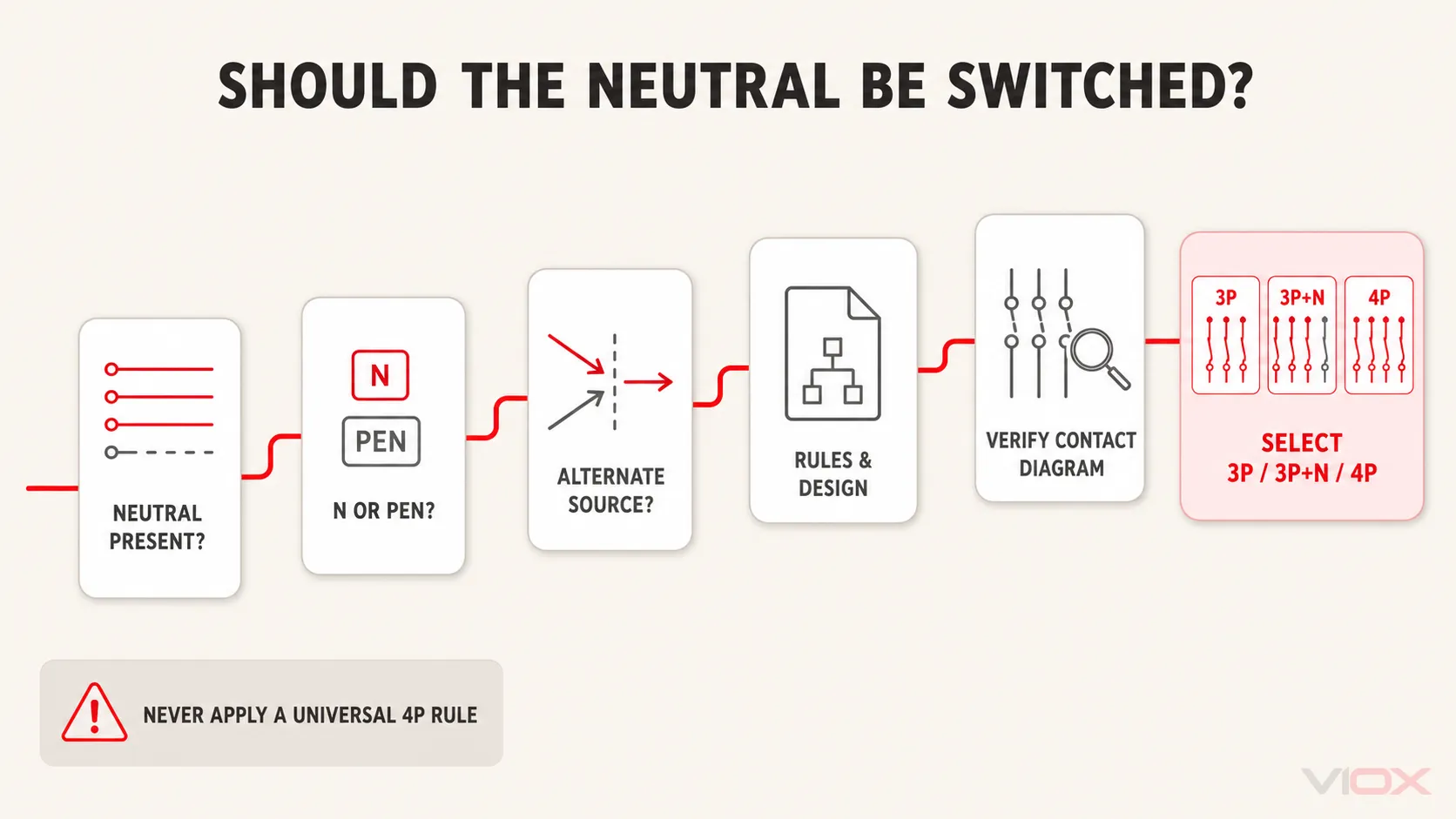
If any answer is unknown, pause the part-number selection. A larger ampere rating cannot correct an unsuitable neutral strategy.
How to Read a 3 Phase Isolator Wiring Diagram
A useful conceptual diagram should show functions, not pretend that every model has the same terminal numbering.
| Diagram item | What it should establish | What it cannot prove by itself |
|---|---|---|
| L1, L2, L3 paths | All required phase poles operate together | Exact terminal location or phase sequence at a specific product |
| Optional N path | Whether the neutral passes through a dedicated or fourth pole | Whether switching the neutral is required or permitted in the project |
| PE path | Protective earth remains a continuous protective connection | Bonding details for the complete installation |
| Upstream SCPD | Fault protection is outside the basic isolator function | Coordination without the exact fuse/breaker and conditional-rating data |
| Contact state | The diagram’s defined unoperated/open/closed condition | Safe isolation of an installed circuit without an approved verification procedure |
Never infer a connection by enclosure appearance. Two rotary devices can share the same handle and housing while having different pole diagrams, utilization categories, line/load conventions, or DC/AC declarations. For AC-versus-DC suitability, use the dedicated DC isolator vs AC isolator switch comparison.
Installation and verification must be performed by appropriately qualified personnel using the approved project drawing, the exact manufacturer’s instructions, and the applicable rules. Moving a handle to OFF is not, by itself, a complete safe-isolation procedure.
Ratings That Must Match the Three-Phase Application
The front current value is only one field. A defensible specification links each rating to the actual circuit and duty.
| Rating or declaration | Selection question | Common error |
|---|---|---|
| Device function | Is it a disconnector, switch, or switch-disconnector? | Assuming every “isolator” can break load current |
| Ue — rated operational voltage | Is the AC operational voltage suitable for the system? | Using Ui as the normal operating voltage |
| Ie — rated operational current | Is Ie adequate at the required Ue and utilization category? | Selecting from the largest ampere marking only |
| Utilization category | Does the declared category match resistive, mixed, or motor/highly inductive duty? | Treating AC-21 and AC-23 values as interchangeable |
| Operating suffix | Is the A/B duty declaration appropriate where stated? | Ignoring operating-frequency conditions |
| Poles and contact behavior | Does the diagram match L1/L2/L3/N treatment? | Treating 3P+N and 4P as universal equivalents |
| Icw and Icm | Can the device withstand and make the declared short-circuit currents under the specified conditions? | Treating withstand or making capacity as automatic interruption |
| Conditional short-circuit rating | Is the exact upstream SCPD and arrangement documented? | Using the rating with a different fuse or breaker |
| Enclosure and operator | Does the complete assembly meet access, lockability, environment, and mounting needs? | Assigning the enclosure’s IP claim automatically to a modified assembly |
| Market evidence | Does the exact model have the required certificate and instructions? | Inferring approval from a family brochure or logo |
Utilization Categories for Common AC Duties
For IEC-oriented switch-disconnectors, utilization category is part of the operational rating:
- AC-20: connecting or disconnecting under no-load conditions;
- AC-21: resistive loads, including moderate overloads;
- AC-22: mixed resistive and inductive loads, including moderate overloads; and
- AC-23: motor loads or other highly inductive loads.
Use the manufacturer’s exact table at the project voltage. A device can have different Ie values across utilization categories, and an enclosure, ambient condition, terminal arrangement, or operating frequency can further limit the usable declaration. The broader isolator switch selection guide provides a complete input-to-specification workflow.
Short-Circuit Coordination Is a Separate Gate
A switch-disconnector can have rated short-time withstand current (Icw), rated short-circuit making capacity (Icm), and a conditional short-circuit rating when protected by a specified SCPD. None of those declarations means the switch automatically detects and clears an overload or short circuit.
Record the prospective short-circuit current, the exact upstream fuse or circuit breaker, the switch’s declared ratings, and every condition attached to the combination. IEC identifies conditional short-circuit requirements for switches and disconnectors protected by circuit breakers within the current IEC 60947-3 publication framework.
Three Bounded Application Examples
Three-Wire Motor Circuit
A motor circuit with L1, L2, and L3 and no distributed neutral may use a 3P arrangement when the system design and applicable rules support it. If the device will routinely make or break motor current, verify a switch-disconnector rating for the required motor/highly inductive duty—typically the relevant AC-23 declaration—rather than selecting an isolation-only device from its ampere value.
Four-Wire Distribution Circuit
A downstream board or mixed-load circuit may include L1, L2, L3, and N. Whether the neutral must be disconnected depends on the earthing arrangement, source and downstream architecture, applicable rules, and the approved design. If the neutral is switched, confirm whether the product is 3P+N or 4P, how the N pole is rated and sequenced, and whether all relevant sources are isolated.
Generator, UPS, ATS, or Inverter System
Alternate-source systems require a source-and-neutral diagram before selecting the switch. A neutral may be common, switched, separately derived, or referenced elsewhere depending on the architecture. A generic rule such as “always use 4P” can create an unintended floating reference or fail to isolate an alternate path. The engineer should resolve source bonding, neutral treatment, transfer sequence, and protective-device coordination before choosing the pole configuration.
Copy-Ready 3 Phase Isolator Specification Record
Complete this record before requesting a part number or quotation.
| Specification field | Project entry |
|---|---|
| Required function | [Disconnector / switch-disconnector / fuse switch-disconnector] |
| System | [Three-phase three-wire / three-phase four-wire / alternate-source architecture] |
| Earthing and neutral arrangement | [System type], [N or PEN], [neutral-switching decision authority] |
| Supply | [AC voltage], [frequency] |
| Load duty | [Resistive / mixed / motor or highly inductive / defined application] |
| Operational rating | Ie ≥ [required value] at Ue [value] under [utilization category] |
| Pole arrangement | [3P / 3P+N / 4P], contact diagram required |
| Neutral-pole behavior | [N marking], [rating], [make/break sequence], or not applicable |
| Short-circuit coordination | [Prospective current], [upstream SCPD], [Icw/Icm/conditional data] |
| Construction | [DIN rail / panel / door coupled / enclosed], [handle/shaft/interlock/lock] |
| Environment | [Complete-assembly IP/NEMA need], [ambient/altitude/corrosion conditions] |
| Market documents | [Destination], [standard/approval], exact model documents required |
Short Answers to Common 4-Pole Questions
Is a 4 pole isolator required for every three-phase system?
No. Use a four-pole arrangement only when the circuit architecture, neutral treatment, applicable rules, and equipment requirements call for the neutral or fourth conductor to be switched. A three-wire load with no neutral can have a different requirement.
Can a 4 pole isolator be used for a single-phase circuit?
Only when the exact manufacturer’s documentation permits the proposed poles and connection arrangement and the device has suitable operational ratings. Do not parallel unused poles or invent a connection to increase current or voltage capability.
Is 3P+N the same as 4P?
Not necessarily. A 3P+N device can have a dedicated neutral pole with different marking, rating, or first-make/last-break behavior. A 4P label also does not prove that all four poles are identical. The contact diagram and datasheet decide.
Does a 4 pole isolator provide overload protection?
Not by pole count. A basic disconnector or switch-disconnector does not automatically detect overcurrent. Protection must come from the correctly selected and coordinated protective arrangement unless the product is a documented fuse-combination or protective device.
From System Record to Product Evaluation
After the system and neutral decisions are approved, compare documented options in the VIOX isolator switch category and switch-disconnector category. For model-level assistance, send the completed specification record, one-line diagram, quantity, and destination market to [email protected]. VIOX should confirm the exact rating table, contact diagram, accessories, and documentation against the supplied project requirements.
Technical Sources
- IEC 60947-3:2020+AMD1:2025 — switches, disconnectors, switch-disconnectors and fuse-combination units
- Schneider Electric — three- or four-pole switching in a cited NEN 1010 context
- Schneider Electric — model-specific 3P+N neutral-pole sequence
- Hager — model-specific four-pole load-break switch ratings