On this page
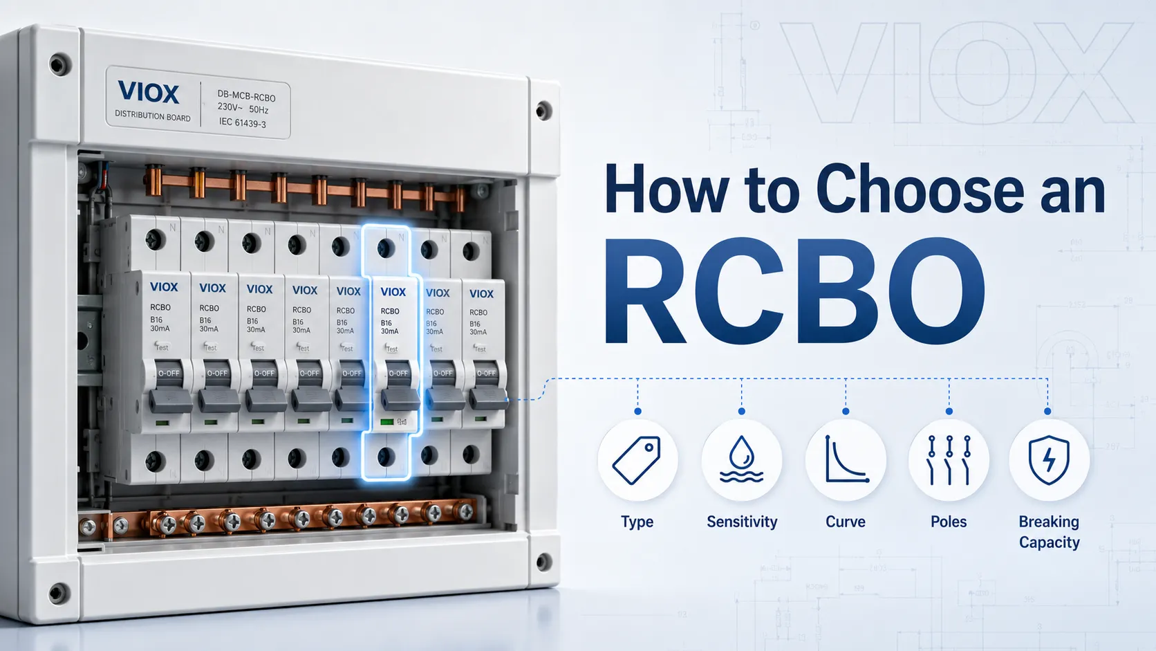
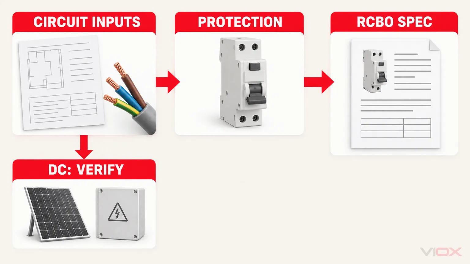
To select the right RCBO, start with the circuit—not the catalog. Establish the load current, corrected conductor capacity, possible residual-current waveform, required residual sensitivity, inrush current, monitored conductors, maximum prospective short-circuit current, supply characteristics, and required product approval. Then specify the RCBO in this order:
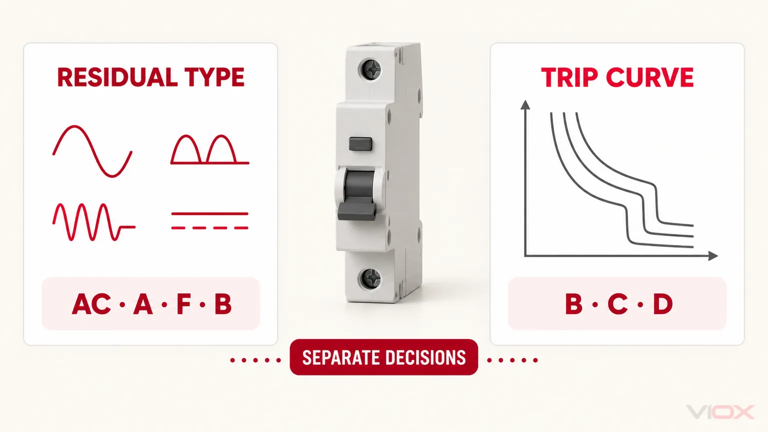
- Residual-current type: AC, A, F, or B
- Residual sensitivity,
IΔn: such as 10 mA, 30 mA, 100 mA, or 300 mA where permitted and required - Rated current,
In: coordinated with design current and conductor capacity - Overcurrent curve: normally B, C, or D for relevant IEC-style products
- Poles and neutral arrangement: matching every conductor that must be monitored and disconnected
- Short-circuit capacity: not less than the maximum prospective short-circuit current under the applicable declaration or an exact documented combination
- Product conditions: voltage, frequency, standard, supply dependence, line/load direction, terminals, busbar compatibility, and market approval
Do not approve a model while any of these fields is unknown. A C32 30 mA Type A 6 kA RCBO is not merely a “32 A breaker”; each marking answers a separate engineering question.
AC scope boundary: This guide primarily addresses AC RCBOs within the scope of IEC/EN 61009-1. The 2024 IEC edition covers relevant RCBOs at rated operational voltages not exceeding 440 V AC and rated frequencies of 50 Hz, 60 Hz, or 50/60 Hz, within its other stated limits. For a DC circuit, stop and verify the applicable DC protective-device standard, polarity, voltage per pole, arc-extinguishing design, disconnection arrangement, and exact manufacturer documentation. Do not transfer the AC selection result to a DC device.
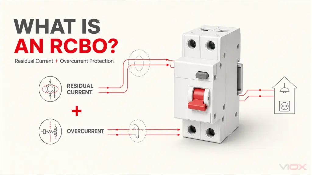
If you first need to understand the device rather than select it, begin with What Is an RCBO?. The RCBO full form guide separately owns abbreviation intent.
RCBO Selection Input Sheet
Collect these inputs before comparing models. “To be confirmed” is a valid design status; guessing a rating is not.
| Input | What to record | Why it changes the RCBO choice |
|---|---|---|
| Supply | For this guide: AC voltage, frequency, phases, neutral, and earthing context; flag any DC circuit for a separate standards and product review | Controls product scope, poles, monitoring, polarity, and declared ratings |
| Circuit duty | Lighting, sockets, heater, motor, inverter, EV charger, PV, mixed load, or another defined duty | Indicates leakage waveform, normal leakage, inrush, and continuity needs |
Design current, IB |
Maximum expected load current using the project design method | Sets the lower bound for the overcurrent rating |
Conductor capacity, IZ |
Corrected ampacity after installation method, ambient temperature, grouping, insulation, and other derating | Sets the upper bound for the protective-device rating |
| Inrush or starting current | Magnitude and duration from equipment data or design evidence | Helps distinguish B, C, or D curve suitability |
| Residual-current evidence | Equipment instructions, converter topology, possible AC, pulsating DC, mixed-frequency, or smooth DC components | Determines Type AC, A, F, or B suitability |
| Normal leakage budget | Per-load leakage, filters, long cables, SPDs, and grouped equipment | Prevents an unrealistically sensitive or overloaded residual-current arrangement |
| Protection purpose | Additional protection, upstream residual-current protection, fault/fire-risk mitigation, or coordination where permitted | Informs IΔn and time-delay or selectivity requirements |
| Maximum PSCC | Maximum prospective short-circuit current at the exact installation point | Sets the minimum applicable breaking capacity |
| Disconnection arrangement | Conductors to be monitored, switched, and protected | Determines 1P+N, 2P, 3P, 3P+N, or 4P arrangement |
| Installation system | Enclosure, DIN rail, busbar, terminal conductors, ambient limits, supply direction | Controls mechanical and declared installation compatibility |
| Compliance | Required product standard, national adoption, certification, project specification | Determines whether a technically plausible device is legally and contractually acceptable |
RCBO Rating Chart: What Each Marking Decides
This chart prevents the most common selection error: treating unrelated markings as substitutes.
| RCBO field | Typical markings or options | Select it from | It does not tell you |
|---|---|---|---|
| Residual-current type | AC, A, F, B | Possible residual-current waveform and equipment instructions | Overcurrent inrush tolerance |
| Residual sensitivity | IΔn, for example 30 mA |
Protection purpose, local rules, leakage budget, and selectivity design | Continuous load rating |
| Rated current | In, for example 16 A, 20 A, 32 A |
IB, corrected IZ, and installation conditions |
Short-circuit breaking capacity |
| Trip curve | B, C, D | Inrush, fault current, loop conditions, and disconnection requirements | Residual-current Type B capability |
| Poles | 1P+N, 2P, 3P, 3P+N, 4P | Supply and required monitored/disconnected conductors | Exact terminal arrangement |
| Breaking capacity | 6 kA, 10 kA, 16 kA, or another declared value | Maximum PSCC, standard, voltage, and exact backup evidence | Rated current or residual sensitivity |
| Voltage and frequency | Ue, 50/60 Hz, other declared values |
Actual supply | Market acceptance |
| Standard and approvals | IEC/EN 61009-1, IEC 62423 where applicable, national marks | Destination market and project specification | Suitability for every installation environment |
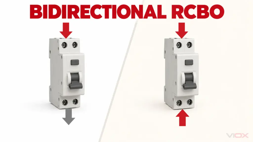
| Direction and supply dependence | Bidirectional/unidirectional; functionally dependent/independent of line voltage | Exact product documentation and system design | A universal wiring arrangement |
Step 1: Select the Residual-Current Type
The residual-current type describes which residual-current waveforms the device is designed to detect. It is independent of the B, C, or D overcurrent curve.
| Type | Detection boundary in practical terms | Selection direction |
|---|---|---|
| Type AC | Sinusoidal AC residual current | Consider only where the connected equipment and local rules allow it |
| Type A | Sinusoidal AC plus pulsating DC residual current | Common starting point for many modern single-phase electronic loads, but not universal |
| Type F | Type A behavior plus defined composite-frequency behavior for relevant single-phase equipment | Consider when equipment or design evidence identifies inverter-related residual currents within its scope |
| Type B | Broader response including smooth DC residual current under its declared conditions | Consider when equipment can produce smooth DC or other residual currents that require Type B behavior |
The load category alone is insufficient. An EV charger, PV inverter, heat pump, or variable-speed drive can incorporate residual-current monitoring that changes the external protection requirement. Conversely, the words “domestic appliance” do not prove Type AC is acceptable. Verify the equipment manufacturer’s instructions, converter topology, local wiring rules, and coordination with upstream devices.
IEC 62423 defines additional requirements for Type F and Type B residual-current devices used with the relevant general RCD standards. For the full waveform comparison and the important difference between Type B RCBO and B-curve RCBO, use the dedicated RCBO Type AC vs A vs F vs B guide.
Stop condition: do not choose the residual-current type when the equipment’s leakage-current behavior or protection instructions are unavailable.
Step 2: Select Residual Sensitivity (IΔn)
IΔn is the rated residual operating current. It is not the RCBO’s ampere rating and it should not be selected from a “lower is always safer” rule.
IΔn value |
Common design role | What must be checked |
|---|---|---|
| 10 mA | High-sensitivity protection for defined special applications | Local requirement, individual circuit use, and normal leakage margin |
| 30 mA | Additional protection on many final circuits in IEC-derived installations | Circuit scope, local rules, accumulated leakage, and required disconnection behavior |
| 100 mA | Upstream residual-current protection, fault/fire-risk mitigation, or coordination where permitted | Whether downstream additional protection remains required and whether selectivity is documented |
| 300 mA | Upstream or fire-risk strategy where specified | Earthing system, local rules, downstream coordination, and time delay where required |
These are roles, not universal prescriptions. Estimate or obtain the circuit’s normal standing leakage, including connected equipment, EMC filters, long cable runs, surge protective devices, and future loads. An RCBO can trip correctly yet still create poor service continuity if normal leakage sits too close to the selected operating threshold.
Where upstream and downstream residual-current devices are used, selectivity depends on more than different mA values. Time characteristics, device type, circuit arrangement, and manufacturer or project evidence also matter.
Stop condition: do not finalize IΔn until the protection purpose and local installation rule are known.
Step 3: Coordinate Rated Current with the Load and Conductor
For an IEC-style design, the basic relationship is:
IB ≤ In ≤ IZwhere:
IBis the circuit design current;Inis the RCBO rated current; andIZis the conductor’s corrected current-carrying capacity.
The logic is simple: the device must carry the intended load, but it must not leave the conductor inadequately protected. The IEC 60364-4-43 scope addresses protection against overcurrent in low-voltage installations; the actual conductor calculation must follow the applicable installation standard and project conditions.
IB ≤ In ≤ IZ is a necessary screening condition, not the whole overload-protection verification. Where the applicable installation standard requires it, also verify:
I₂ ≤ 1.45 × IZI₂ is the current that causes effective operation of the protective device within the conventional time defined by the applicable product standard or manufacturer data. Check the actual RCBO characteristic and all conductor-protection conditions required by the local installation standard, including cases where overload protection may be treated differently. The IET provides a public BS 7671 example of the complete IB, In, IZ, and I₂ conditions; use it as an accessible UK example, not as a substitute for the rules governing another market.
Do not use fixed shortcuts such as “2.5 mm² always means 20 A.” Conductor material, insulation, installation method, grouping, ambient temperature, terminals, harmonics, voltage drop, load duty, and national rules can all change the result. The product’s reference ambient and derating information must also be considered when it is installed in a warm or densely populated board.
Stop condition: if corrected IZ is not known, the RCBO ampere rating is not ready for approval.
Step 4: Select the Overcurrent Curve from Inrush and Fault Behavior
B, C, and D are overcurrent characteristics. They indicate different instantaneous magnetic trip regions for relevant IEC-style protective devices; they are not residual-current types.
| Curve | Common reference range | Practical selection question | Main misuse risk |
|---|---|---|---|
| B | About 3–5 × In |
Is normal inrush low enough while required fault disconnection is achieved? | Nuisance tripping on transformers, motors, or large driver groups |
| C | About 5–10 × In |
Does the circuit have moderate inrush and sufficient fault current? | Assuming it is a universal “commercial” curve |
| D | About 10–20 × In |
Is high inrush documented, and can the circuit still meet fault-disconnection requirements? | Using it to mask startup trips where fault current is too low |
Use the equipment’s starting-current data and duration, then check the manufacturer’s time-current curve and the project’s fault or loop conditions. A higher-inrush curve can ride through startup current, but it also needs a higher current to enter its instantaneous region.
For graph reading, thermal behavior, magnetic bands, and coordination limits, use the circuit-breaker trip-curve guide.
Stop condition: do not move from B to C or D only because an existing device trips. First determine whether the event is overload, short circuit, residual current, incorrect wiring, normal leakage accumulation, or genuine inrush.
Step 5: Select Poles and the Neutral Arrangement
Every conductor that must be included in the residual-current measurement must pass through the device’s intended sensing path. The required disconnection arrangement depends on the supply, earthing system, local rules, and circuit function.
| Configuration | Typical system context | Required verification |
|---|---|---|
| 1P+N | Single-phase final circuit | Which pole has overcurrent protection, whether neutral is switched or solid, terminal layout, and permitted supply direction |
| 2P | Single-phase circuit requiring two-pole disconnection | Whether both poles are switched, which poles are protected, and how the product monitors the conductors |
| 3P | Three-phase circuit without a neutral | All three phase conductors follow the declared current path and product diagram |
| 3P+N / 4P | Three-phase circuit with neutral | Neutral monitoring and switching behavior, pole protection, and exact terminal diagram |
Marketing names are not wiring diagrams. Two products called 1P+N can differ in neutral treatment, supply dependence, terminal position, or line/load direction. Use the exact catalog number and product drawing.
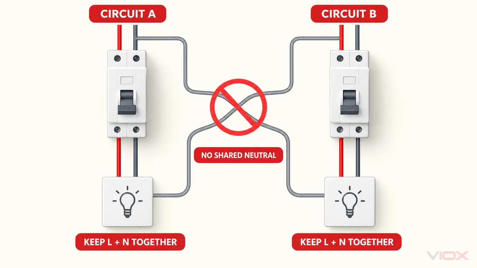
Never borrow or share a downstream neutral between separate RCBO circuits. The returned current will not match the monitored line current, which can cause tripping and unsafe commissioning assumptions. See shared neutrals and RCBO tripping for the fault logic. Use the RCBO wiring diagram guide only as a configuration reference; the selected model’s diagram remains controlling.
Stop condition: if neutral treatment or terminal direction is ambiguous, obtain the exact datasheet before approving the device or panel layout.
Step 6: Verify Short-Circuit Breaking Capacity
The applicable declared short-circuit capacity must not be less than the maximum prospective short-circuit current at the installation point:
RCBO breaking capacity ≥ maximum PSCC at the installation pointRead the kA figure together with the product standard, voltage, current type, and exact catalog number. A 6 kA rating can be adequate at one board and inadequate at another. A 10 kA or 16 kA label does not compensate for the wrong In, curve, IΔn, or residual-current type.
If the standalone device rating is below the fault level, an upstream protective device may support it only through an exact manufacturer-documented backup, cascading, or conditional combination. “There is a fuse upstream” is not evidence. An assembly’s conditional short-circuit rating also does not automatically become the standalone rating of every RCBO inside it.
Use the focused RCBO 6 kA vs 10 kA vs 16 kA selection guide to distinguish device capacity from verified combination and assembly ratings.
Stop condition: if the maximum credible PSCC is unknown, do not finalize the RCBO kA rating.
Step 7: Verify the Exact Product, Standard, and Installation Conditions
IEC 61009-1 covers residual-current operated circuit-breakers with integral overcurrent protection for household and similar uses within its published scope. The current public catalog entry is IEC 61009-1:2024. A standard reference is only one field in the approval check; the destination market may require a national adoption, certification mark, or a different product framework.
Verify the exact RCBO datasheet and nameplate for:
- rated operational voltage and frequency;
- rated current, residual operating current, residual-current type, and trip curve;
- poles, protected poles, switched-neutral behavior, and terminal identification;
- applicable short-circuit-capacity declaration and voltage;
- function with or without line voltage, where relevant;
- permitted line/load direction and bidirectional-use declaration;
- temperature limits and derating;
- conductor type, terminal capacity, tightening requirements, and busbar compatibility;
- isolation indication and accessory compatibility where the project requires them;
- product standard, approvals, certification, and document revision; and
- coordination tables when the design depends on upstream backup or selectivity.
For a deeper product-standard explanation, use the IEC 61009-1 RCBO guide.
Stop condition: a family brochure is insufficient when the required claim is model-, voltage-, pole-, or combination-specific.
Worked Example: From Circuit Inputs to One RCBO Specification
This hypothetical example demonstrates the method; it is not a model recommendation or a reusable circuit schedule.
Given Inputs
Assume a dedicated single-phase load has the following verified design record:
| Input | Example value | Evidence status |
|---|---|---|
| Supply | 230 V AC, 50 Hz, line and neutral | Inside the voltage/frequency scope being considered; market acceptance still requires verification |
Design current, IB |
18 A | From the project load calculation |
Corrected conductor capacity, IZ |
24 A | After the project’s installation and derating factors |
Candidate device rating, In |
20 A | Candidate for coordination check—not yet selected |
Candidate conventional operating current, I₂ |
29 A | From the applicable product-standard characteristic or exact manufacturer data for the hypothetical candidate |
| Equipment residual-current information | Pulsating DC may occur; no smooth DC or composite-frequency requirement identified | From the hypothetical equipment documentation |
| Project residual-current requirement | 30 mA additional protection | Assumed to be required by the applicable project and local installation rules |
| Starting current | 75 A for 20 ms | From the hypothetical equipment data |
| Maximum PSCC at the board | 4.2 kA | From the hypothetical project fault-current record |
| Disconnection arrangement | Single-phase circuit with line and neutral; neutral treatment to be confirmed from the exact device | From the project single-line diagram plus product documentation |
1. Check Rated Current and Overload Protection
The basic current relationship passes:
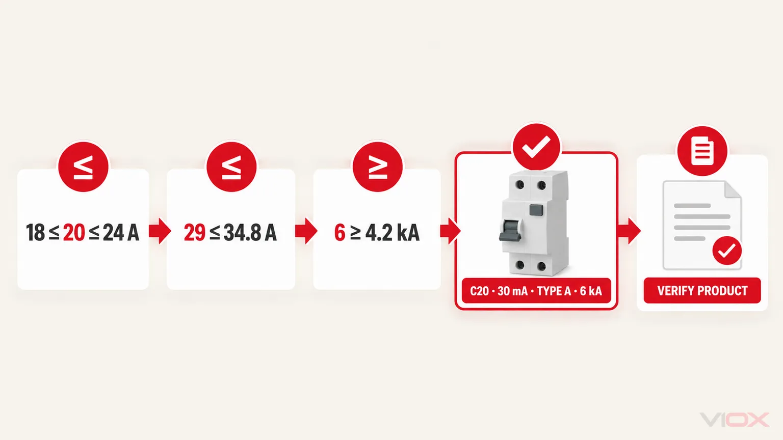
18 A ≤ 20 A ≤ 24 AThe additional example check also passes:
I₂ = 29 A1.45 × IZ = 1.45 × 24 A = 34.8 A29 A ≤ 34.8 AThis does not complete the cable design. The applicable installation standard may impose additional conductor, overload, fault-protection, voltage-drop, thermal, grouping, terminal, or disconnection requirements.
2. Select Residual-Current Type and Sensitivity
The hypothetical equipment record identifies pulsating DC residual current but no evidence requiring Type F or Type B behavior. Type A is therefore the candidate residual-current type. The project requirement supplies the 30 mA value. Both fields still require confirmation against the actual equipment manual, local rules, and exact RCBO documentation.
3. Check the Trip Curve
The starting current is 75 A ÷ 20 A = 3.75 × In for 20 ms. That ratio alone does not select the curve. Compare the complete inrush duration with the exact manufacturer time-current band and verify fault-disconnection performance. In this example, assume the documented study confirms that a C curve rides through the stated inrush and still satisfies the required fault-disconnection conditions. Without that study, the curve remains unresolved.
4. Check Breaking Capacity
The maximum prospective short-circuit current (PSCC) is 4.2 kA. A candidate with an applicable standalone 6 kA declaration at 230 V AC is not below that value:
6 kA ≥ 4.2 kAThe exact standard, voltage, model, and any assembly conditions must still match. No generic safety multiplier or undocumented upstream backup has been assumed.
5. Produce the Bounded Output
Subject to the stated evidence and final product verification, the example output becomes:
Hypothetical RCBO specification: 1P+N arrangement as defined by the exact product; 230 V AC, 50 Hz; C20; 30 mA; Type A; applicable standalone short-circuit capacity of at least 4.2 kA, with a 6 kA candidate; IEC/EN 61009-1 product framework; required national approval; exact neutral treatment, supply dependence, line/load direction, terminals, temperature limits, and busbar compatibility to be confirmed from the selected catalog number.
If the inrush study, Type A evidence, 30 mA project requirement, or exact product declaration changes, the output must be recalculated. The example is intentionally conditional so the method cannot be mistaken for a universal recommendation.
RCBO Selection by Application: Starting Points, Not Answers
The following table helps identify evidence to collect. It is not a model schedule.
| Application | Common starting direction | Evidence that controls the final choice |
|---|---|---|
| LED lighting group | Often Type A; B or C curve depending on driver inrush | Driver leakage and inrush data, quantity, conductor design, fault conditions, and local rules |
| General socket circuit | Often Type A and 30 mA in many IEC-derived designs | Connected equipment, local additional-protection rules, leakage budget, IB, IZ, and PSCC |
| Heater or simple resistive load | Type and curve based on actual controls and inrush | Electronic controls, switching arrangement, conductor design, and local requirements |
| Motor, pump, or compressor | Type A, F, or B depending on drive topology; curve from starting data | Direct-on-line or electronic drive, leakage waveform, starting current and duration, fault level |
| Heat pump or inverter air conditioner | Type F or B may be required for some equipment | Manufacturer instructions, converter topology, residual-current monitoring, and local rules |
| EV charging | The permitted route may include Type B or another documented DC-residual-current strategy | EVSE design, integrated 6 mA DC detection where applicable, local rules, upstream coordination, and charger instructions |
| PV inverter AC circuit | Type A or B depending on inverter design and requirements | Inverter topology, built-in residual-current monitoring, manufacturer instructions, and national PV rules |
| Upstream distribution | Higher IΔn and time selectivity may be part of the design |
Earthing arrangement, fire-risk strategy, downstream devices, discrimination study, and local code |
Do not copy the “common starting direction” into a bill of materials. The evidence in the final column owns the decision.
Final RCBO Specification Template
A selection is complete when it can be written and checked in one line plus its supporting evidence. Use this template:
RCBO: [poles and neutral arrangement], [rated voltage/frequency],
In[A], [B/C/D or other declared curve],IΔn[mA], residual-current Type [AC/A/F/B], short-circuit capacity [kA] under [standard and voltage], [direction/supply-dependence requirement], [national approval], installed in [board/busbar/terminal system], with [exact backup/selectivity document if used].
Attach or reference:
- load schedule and
IBcalculation; - corrected conductor capacity
IZ; - equipment leakage-waveform and inrush evidence;
- normal leakage budget where relevant;
- maximum PSCC source and date;
- exact product datasheet and wiring diagram;
- local code or project requirement; and
- manufacturer coordination table when the design depends on a combination.
If those records do not support every field, the selection is incomplete. If the panel architecture itself is still undecided, compare individual RCBOs with an RCCB plus MCB arrangement before preparing the schedule.
Selection Review Checklist
Primary Technical Sources
- IEC 61009-1:2024 — RCBOs with integral overcurrent protection
- IEC 62423 — Type F and Type B residual-current devices
- IEC 60364-4-43:2023 — Protection against overcurrent
- IET Wiring Matters — accessible BS 7671 example of
IB,In,IZ, andI₂overload conditions
Once the circuit data and required fields are complete, compare them with the documented VIOX RCBO range. Request the exact model datasheet, certification, terminal diagram, and any required backup or selectivity table rather than selecting from a family name alone.