On this page
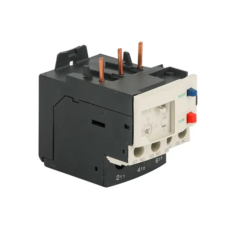
A thermal overload relay is a motor protection device that trips when motor current stays too high for too long. It is designed to protect the motor from overload heating, not from short-circuit faults.
In one sentence: a thermal overload relay opens the contactor control circuit when motor current remains above the set value long enough to create an overheating risk.
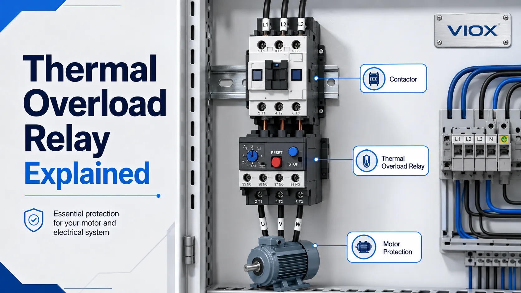
In a typical motor starter, the contactor switches the motor on and off, while the thermal overload relay monitors motor current and opens the control circuit if the motor is overloaded. This prevents the motor from continuing to run under damaging thermal stress.
The key point is simple: a thermal overload relay protects against sustained overload current; a fuse, MCB, MCCB, or MPCB is still required for short-circuit protection.


Key Takeaways
- A thermal overload relay protects motors from overheating caused by overload, locked rotor, long starting time, or phase-loss related overcurrent.
- It normally works with a contactor. The overload relay trips the contactor coil circuit through a normally closed overload contact.
- It does not replace short-circuit protection. You still need a suitable fuse, breaker, or motor protection circuit breaker upstream.
- Selection depends on motor full-load current, trip class, reset mode, phase-loss sensitivity, contact arrangement, and contactor compatibility.
- Common overload relay output contacts include a normally closed trip contact for stopping the contactor and a normally open auxiliary contact for alarm or signal use.
Thermal Overload Relay at a Glance
| Item | Practical Meaning |
|---|---|
| Main function | Protects a motor against sustained overload heating |
| Protection type | Time-delay thermal protection |
| Typical installation | Between contactor and motor, or integrated with a motor starter assembly |
| Main setting | Current setting matched to motor full-load current |
| Common trip contact | NC contact opens the contactor coil circuit when overload occurs |
| Reset modes | Manual reset or automatic reset, depending on application |
| Not designed for | Clearing short-circuit current by itself |
| Common standard context | Motor starters and contactors are commonly handled under IEC 60947-4-1 or related market standards |
How a Thermal Overload Relay Works
A thermal overload relay uses heat created by motor current to simulate motor heating. When the current remains above the set value long enough, the relay trips.
The operating logic follows the motor’s thermal behavior:
- small overloads should not trip instantly;
- sustained overloads should trip after a delay;
- severe overloads should trip faster;
- normal starting current should be tolerated if it is within the selected trip class and motor starting profile.
This is why a thermal overload relay is not an instantaneous device. It has an inverse-time behavior: the higher the overload current, the faster the trip.
Why Thermal Overload Relays Trip Slowly
A thermal overload relay trips slowly because motor damage is usually caused by heat accumulated over time, not by a momentary current spike. A motor may draw high current during starting, but that does not necessarily mean it is overloaded.
The relay therefore uses a time-delay curve. It allows normal starting current for a limited time, but trips if the current remains above the setting long enough to overheat the motor. This is why trip class, starting time, and motor load type matter so much in selection.
Bimetallic Thermal Overload Relay Working Principle
The most common thermal overload relay design uses a bimetallic strip. A bimetallic strip is made from two metals with different thermal expansion rates. When current heats the strip, it bends. If the bending reaches the trip mechanism, the overload relay opens the trip contact.
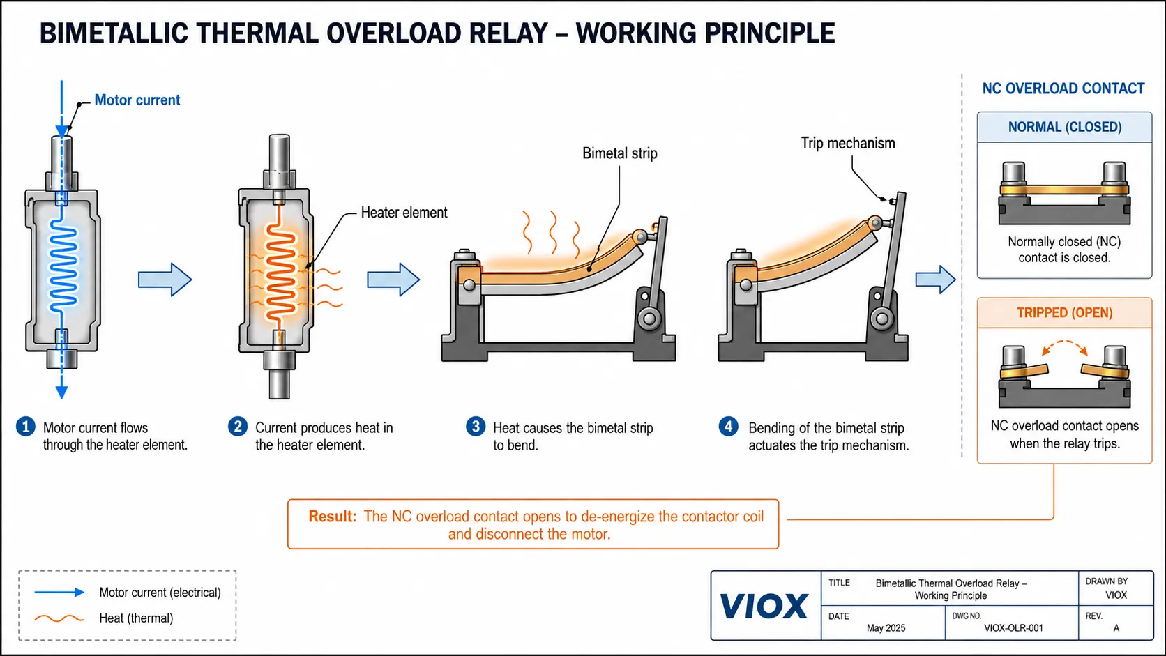
In a motor starter, that trip contact is wired into the contactor coil circuit. When the contact opens, the contactor drops out and disconnects the motor from the power supply.
This mechanical thermal memory is useful because motor damage is related to heat over time, not only to a single current value.
Melting Alloy Thermal Overload Relay
Some overload relays use a melting alloy, also called a eutectic alloy mechanism. In this design, overload current heats an element until a calibrated alloy melts or changes state, allowing the trip mechanism to operate.
The purpose is still the same: convert sustained overcurrent into a delayed trip that reflects motor heating. The eutectic alloy provides a calibrated thermal element, so the relay trips only after the overload condition has produced enough heat.
Thermal Overload Relay Contacts: NC, NO, and Overload Contact Function
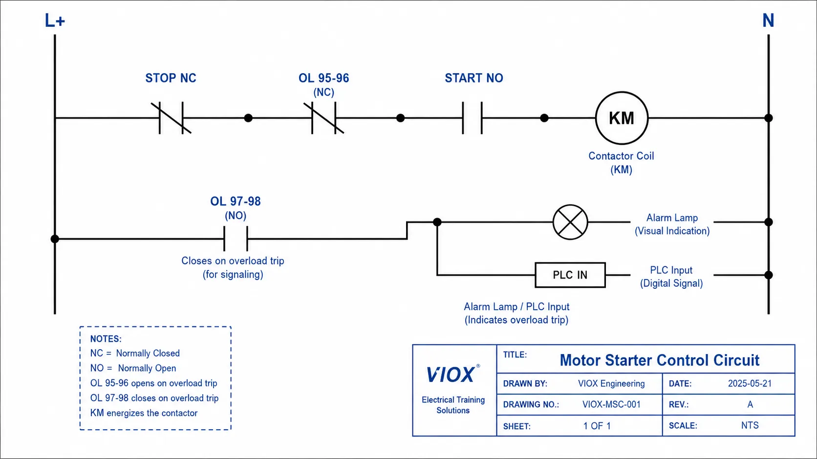
Most thermal overload relays provide at least one trip contact. In many IEC-style devices, the common convention is:
| Contact | Common Terminal Marking | Function |
|---|---|---|
| Normally closed trip contact | 95-96 | Opens when the overload relay trips, breaking the contactor coil circuit |
| Normally open signal contact | 97-98 | Closes when the relay trips, used for alarm, PLC input, or fault indication |
The exact markings and contact ratings must be checked on the device datasheet, but the control logic is usually the same: the NC overload contact stops the motor starter, and the NO contact reports the overload condition.
Basic Contactor and Thermal Overload Relay Ladder Logic
L+  ──[ STOP NC ]──[ OL 95-96 NC ]──[ START NO ]──( KM contactor coil )── N
                         |
                         +── opens on overload trip
In a standard ladder diagram, the NC overload contact is placed in series with the contactor coil. When the overload relay trips, the 95-96 contact opens, the contactor coil loses power, the main contacts open, and the motor stops. The 97-98 NO contact, if used, can signal an alarm lamp or PLC input.
For complete motor control selection, see VIOX’s guide to selecting contactors, overload relays, and circuit breakers for motor power.
What Does a Thermal Overload Relay Protect?
A thermal overload relay mainly protects the motor against overheating caused by excessive current over time.
| Condition | Can Thermal Overload Relay Help? | Notes |
|---|---|---|
| Motor overloaded mechanically | Yes | Common use case |
| Long starting time | Yes, if trip class is selected correctly | Incorrect trip class may cause nuisance tripping |
| Locked rotor | Often yes, within relay capability | Short-circuit protection still required |
| Phase loss / single phasing | Some models provide sensitivity | Do not assume every model handles phase loss equally |
| Short circuit | No, not by itself | Requires fuse, MCB, MCCB, or MPCB |
| Ground fault | No, not by itself | Requires suitable residual-current or ground-fault protection |
| Motor winding temperature | Indirectly | Built-in thermal sensors provide more direct winding protection |
Ambient Compensation: Why Control Cabinet Temperature Matters
Control cabinet temperature can affect thermal overload relay behavior. In a hot enclosure, the bimetal element may already be closer to its trip position before the motor current even rises. That can cause nuisance tripping in summer, near heaters, or inside densely packed panels.
Ambient-compensated thermal overload relays use a compensating bimetal element to reduce the influence of surrounding air temperature. The protection element still responds to motor current heating, but the compensation mechanism helps keep the trip point more stable as cabinet temperature changes.
This does not mean ambient temperature can be ignored. Panel builders should still check ventilation, enclosure temperature rise, contactor heat, cable sizing, and whether the overload relay’s ambient compensation range matches the installation conditions.
Advantages and Limitations of Thermal Overload Relays
| Advantage | Why It Helps |
|---|---|
| Simple motor overload protection | Easy to apply in standard contactor-based motor starters |
| Time-delay behavior | Tolerates normal motor starting current better than an instant trip device |
| Adjustable current setting | Can be matched to motor nameplate current within the relay range |
| NC and NO auxiliary contacts | Supports contactor trip control and alarm signaling |
| Cost-effective for many standard motors | Suitable for many pumps, fans, compressors, and machine motors |
| Limitation | Why It Matters |
|---|---|
| No short-circuit protection by itself | Must be coordinated with a fuse, breaker, or MPCB |
| Limited diagnostics | Mechanical thermal relays usually provide less fault information than electronic relays |
| Selection depends on trip class | Wrong trip class can cause nuisance trips or underprotection |
| Phase-loss protection varies by model | Do not assume all thermal overload relays detect phase loss equally |
| Ambient temperature can affect behavior | Check whether the relay has ambient compensation for cabinet conditions |
Thermal Overload Relay vs Short-Circuit Protection
A thermal overload relay and a short-circuit protective device solve different problems.
| Device | Main Protection | Typical Response | What It Protects |
|---|---|---|---|
| Thermal overload relay | Sustained overload current | Delayed thermal trip | Motor from overheating |
| Fuse | Short circuit and high fault current | Very fast depending on fuse type | Conductors and equipment against high fault current |
| MCB / MCCB | Overload and short circuit depending on type | Thermal and magnetic/electronic trip | Circuit conductors and equipment |
| MPCB | Motor overload and short-circuit protection depending on design | Motor-specific protection | Motor branch circuit |
Do not use a thermal overload relay as the only protective device in a motor circuit. It is normally part of a coordinated motor starter with short-circuit protection upstream.
For broader fault terminology, see Overload vs Overcurrent vs Short Circuit.
IEC 60947-4-1 Type 1 vs Type 2 Coordination
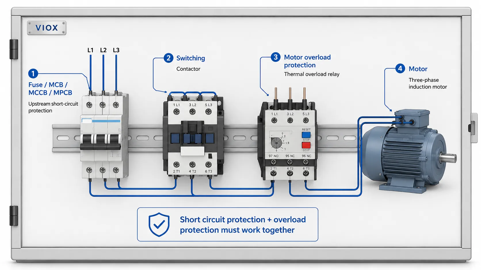
When a thermal overload relay is used with a contactor and short-circuit protective device, engineers also need to consider starter coordination. In IEC 60947-4-1 context, Type 1 and Type 2 coordination describe what condition the starter is allowed to be in after a short-circuit test.
| Coordination Type | Practical Meaning | Why It Matters |
|---|---|---|
| Type 1 coordination | The starter must not create danger, but components may need repair or replacement after the fault | Lower cost, but downtime and replacement may be expected |
| Type 2 coordination | The starter must remain suitable for further service after the fault, with limited contact welding allowed under defined conditions | Higher availability and better for critical machinery |
This is not a rating that the overload relay provides alone. It depends on the tested combination of contactor, overload relay, and upstream short-circuit protective device. For OEM panels and industrial machines, asking only for the overload relay current range is not enough; the complete motor starter combination should be checked.
Thermal Overload Relay Trip Class: Class 10, Class 20, and Class 30
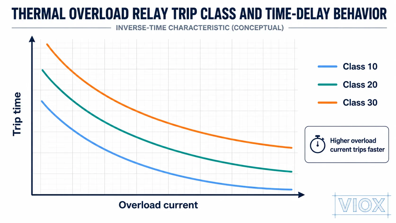
Trip class describes how quickly the overload relay trips under defined overload test conditions. Common classes include Class 10, Class 20, and Class 30.
| Trip Class | Typical Use | Selection Caution |
|---|---|---|
| Class 10 | Standard motors with normal starting time | Too low for heavy-start loads may cause nuisance trips |
| Class 20 | Motors with longer acceleration time | Must still protect the motor from excessive heating |
| Class 30 | Heavy-start applications with long acceleration | Requires careful motor and starter coordination |
Do not choose a higher trip class just to stop nuisance tripping. If the motor is tripping during startup, check starting current, acceleration time, motor load, supply voltage, mechanical load, and whether the starter and overload relay are correctly selected.
How to Select a Thermal Overload Relay
| Selection Factor | What to Check | Why It Matters |
|---|---|---|
| Motor full-load current | Match the relay setting range to the motor nameplate current | The relay must be adjustable to the actual motor FLA |
| Contactor compatibility | Mechanical and electrical fit with the contactor | Many overload relays mount directly under matching contactors |
| Trip class | Class 10, 20, 30, or manufacturer-specific class | Must match motor starting profile |
| Phase-loss sensitivity | Whether the relay detects unbalanced heating or phase loss | Important for three-phase motor protection |
| Reset mode | Manual or automatic | Manual reset is safer for many machines |
| Auxiliary contacts | NC trip contact and NO alarm contact | Needed for contactor control and signaling |
| Ambient compensation | Whether temperature changes affect trip behavior | Useful in control cabinets and warm environments |
| Coordination with short-circuit device | Fuse, MCB, MCCB, or MPCB | Prevents unsafe fault clearing arrangements |
For motor starter architecture, VIOX also covers MCB + contactor + overload relay vs MPCB + contactor.
Manual Reset vs Automatic Reset
Thermal overload relays may support manual reset, automatic reset, or both depending on the model.
| Reset Mode | Meaning | Best Use |
|---|---|---|
| Manual reset | A person must reset the relay after trip | Safer for machinery where automatic restart could be dangerous |
| Automatic reset | Relay resets after cooling | Used only where automatic restart is safe and allowed |
For motor-driven machinery, automatic reset can be risky. If the motor restarts unexpectedly after cooling, it may create mechanical or personnel hazards. Always follow machine safety requirements and local code.
Thermal Overload Relay vs Built-In Motor Thermal Protector
Some motors include inherent motor protection such as thermal switches, thermistors, or embedded temperature sensors. These devices are built into the motor and respond more directly to winding or internal motor temperature.
| Protection Method | Where It Is Located | What It Detects Best | Typical Role |
|---|---|---|---|
| Thermal overload relay | Motor starter or control panel | Current-related motor heating | External overload protection and contactor trip control |
| Built-in thermal protector | Inside the motor | Internal winding or motor temperature | Direct motor temperature protection |
| Motor thermistor / sensor | Embedded in motor winding | Actual winding temperature trend | Used with a protection relay or drive input |
Built-in motor protection does not automatically remove the need for branch-circuit protection or starter overload coordination. In many systems, internal motor protection and external overload protection work together.
Thermal Overload Relay vs Electronic Overload Relay
A thermal overload relay is simple, robust, and widely used. An electronic overload relay uses sensors and electronics to monitor current and may offer more adjustable protection functions.
| Feature | Thermal Overload Relay | Electronic Overload Relay |
|---|---|---|
| Sensing principle | Thermal bimetal or melting alloy | Current sensing and electronic logic |
| Adjustment | Usually simple current setting | Often wider and more precise settings |
| Phase loss protection | Depends on model | Often stronger and more configurable |
| Diagnostics | Limited | May include alarms, trip memory, communication, or display |
| Cost | Usually lower | Usually higher |
| Best fit | Standard motor starter applications | Higher-value motors, process equipment, diagnostics-heavy systems |
If the motor is critical, expensive, difficult to access, or part of a process line, electronic overload protection may justify the additional cost.
Thermal Overload Relay vs Thermal-Magnetic Breaker
The phrase thermal magnetic overload relay is often used loosely, but it can be misleading.
A thermal overload relay is a motor overload protection device. A thermal-magnetic breaker is a circuit breaker with thermal and magnetic trip elements. The breaker protects the circuit against overload and short circuit, while the overload relay is focused on motor thermal protection and contactor control.
In many motor circuits, both are needed: a short-circuit protective device upstream and an overload relay matched to the motor.
Thermal Overload Relay Symbol and Wiring Diagram Notes
In electrical drawings, a thermal overload relay is usually shown as an overload protection element associated with the motor starter. The trip contact is commonly shown as a normally closed auxiliary contact in the contactor coil circuit.
When reading a motor starter diagram, look for:
- the overload relay power path between contactor and motor;
- the NC overload trip contact in series with the contactor coil;
- the NO alarm contact if connected to a PLC or indicator;
- reset mode and trip indication.
This is why the overload relay appears in both the power circuit and the control circuit: it senses motor current in the power path and interrupts the control circuit when it trips.
Troubleshooting: Why a Thermal Overload Relay Keeps Tripping
Repeated thermal overload trips usually mean the motor is overheating, the starter is misapplied, or the relay is set incorrectly. Do not simply increase the current setting to keep production running.
| Symptom | Likely Cause | What to Check |
|---|---|---|
| Trips during motor startup | Trip class too low, starting time too long, low voltage, heavy mechanical load | Motor acceleration time, supply voltage, load inertia, Class 10 vs Class 20/30 suitability |
| Trips after running for several minutes | Mechanical overload, bearing problem, blocked fan, pump overload | Load current on each phase, mechanical resistance, cooling airflow |
| Trips mainly in hot weather | Cabinet temperature rise or poor ventilation | Enclosure temperature, spacing, contactor heat, ambient compensation |
| Trips on one motor but not another | Wrong current setting or relay range | Motor nameplate FLA, relay dial setting, CT ratio if used |
| Trips after phase loss or imbalance | Supply issue or phase-loss condition | Phase voltage, phase current balance, upstream fuse/breaker condition |
| Trips but contactor does not drop out | NC overload contact not wired correctly | 95-96 contact in series with coil circuit, wiring continuity |
Field note: when a motor trips during startup, replacing a Class 10 overload relay with Class 20 may solve nuisance tripping only if the motor and starter are rated for the longer start. A better check is to measure actual starting current, acceleration time, phase voltage, cable voltage drop, and mechanical load before changing the trip class.
Common Selection and Wiring Mistakes
Mistake 1: Treating the overload relay as short-circuit protection
The overload relay protects against sustained thermal overload. It does not safely clear high short-circuit current by itself.
Mistake 2: Setting the current too high to avoid nuisance trips
Increasing the setting can hide a real overload and leave the motor underprotected. First check mechanical load, voltage, starting time, and trip class.
Mistake 3: Ignoring the motor nameplate current
The overload relay should be set according to the motor nameplate and applicable design rules, not guessed from motor horsepower alone.
Mistake 4: Using automatic reset in unsafe machinery
Automatic restart after cooling may be dangerous. Manual reset is often preferred where unexpected motion can create a hazard.
Mistake 5: Forgetting the NC overload contact
If the NC trip contact is not wired in series with the contactor coil, the overload relay may trip mechanically but fail to stop the motor starter as intended.
FAQ
What is a thermal overload relay?
A thermal overload relay is a motor protection device that trips when motor current stays above the setting long enough to create overheating risk. It is used with a contactor in many motor starters.
What does an overload relay do?
It monitors motor current and opens a control contact when the motor is overloaded. This de-energizes the contactor coil and stops the motor.
Does a thermal overload relay protect against short circuit?
No. A thermal overload relay is not a short-circuit protective device. Use a suitable fuse, breaker, or MPCB for short-circuit protection.
What is the function of an overload contact?
The overload contact changes state when the overload relay trips. The normally closed contact is typically used to open the contactor coil circuit, while the normally open contact can be used for alarm or PLC signaling.
What is a thermal relay?
A thermal relay is another common name for a thermal overload relay. In motor control, it usually means a device that trips based on heat produced by sustained current.
What is thermal overload protection?
Thermal overload protection prevents motors or equipment from running too long under excessive current. It is time-delayed because heating damage depends on current and time.
What is a melting alloy thermal overload relay?
It is an overload relay that uses a calibrated alloy mechanism that changes state when heated by overload current. This thermal action trips the relay.
What do thermal overload relays protect in a motor circuit?
They mainly protect the motor from overheating caused by sustained overload current. They do not replace short-circuit, ground-fault, or residual-current protection.
Are inherent motor protection devices built into the motor?
Yes. Inherent motor protection devices are built into the motor, such as thermal sensors or protectors. Their reset behavior depends on the device design, so do not assume every motor resets the same way.
Related VIOX Resources
Conclusion
A thermal overload relay is a core motor protection device. It monitors sustained overload current, trips with a time-delay behavior that reflects motor heating, and opens the contactor control circuit to stop the motor.
For correct selection, match the relay to the motor full-load current, trip class, contactor frame, reset mode, phase-loss requirements, auxiliary contacts, and upstream short-circuit protection. The best motor starter design treats the thermal overload relay as one part of a coordinated protection system, not as a standalone answer to every motor fault.