On this page
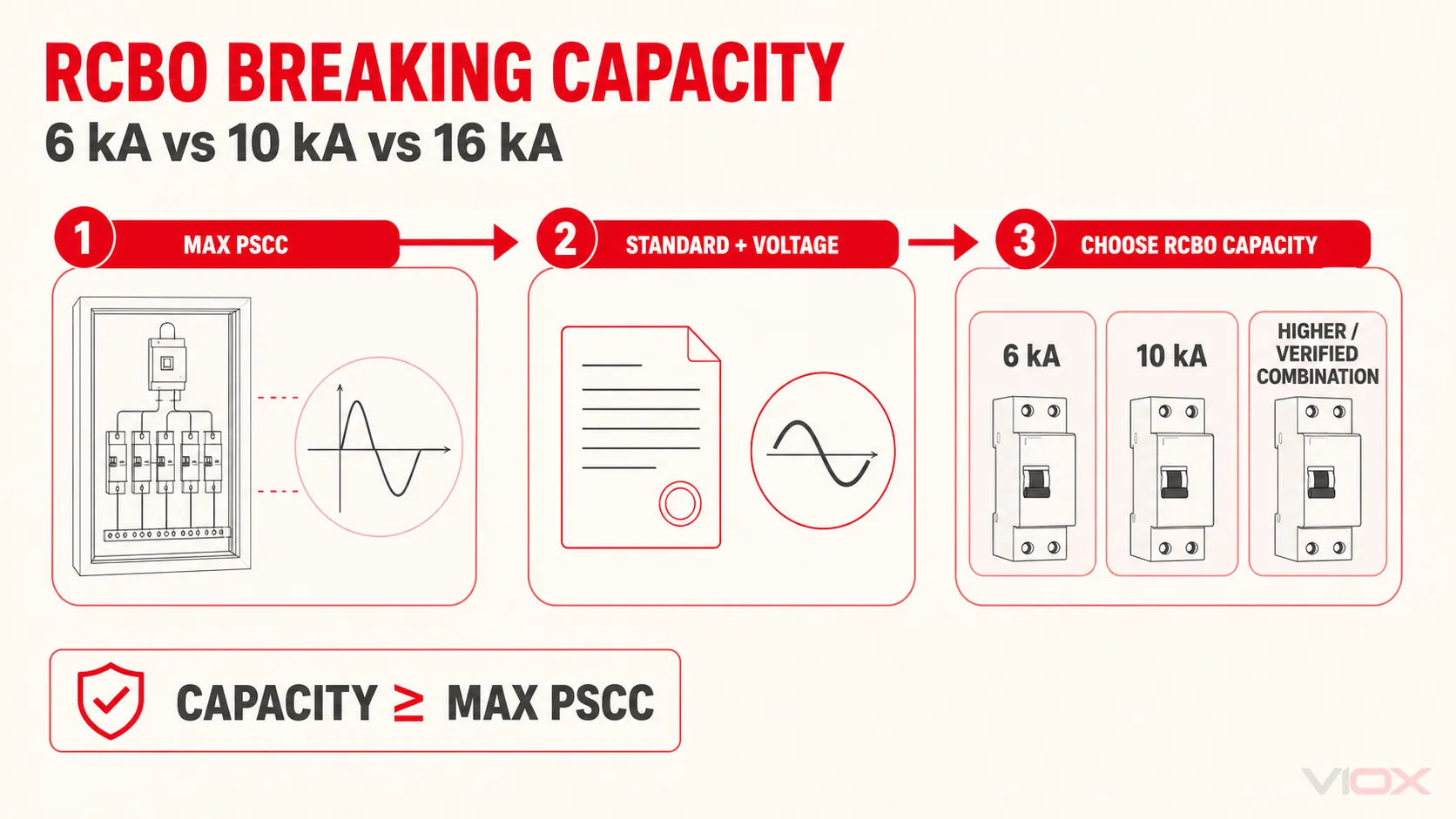
Select an RCBO whose applicable declared short-circuit capacity is not less than the maximum prospective short-circuit current (PSCC) at its installation point. Read the kA value together with the product standard and voltage. Do not choose 6 kA, 10 kA, or 16 kA from the words “residential,” “commercial,” or “industrial” alone.
If a lower-rated RCBO is proposed with upstream backup or cascading protection, the alternative is valid only when the manufacturer documents the exact upstream device, downstream RCBO, voltage, and installation conditions. A switchboard or consumer unit marked with a 16 kA conditional short-circuit rating does not automatically make every installed RCBO a 16 kA device.
| Maximum PSCC at the RCBO point | Minimum direction | What must be verified |
|---|---|---|
| PSCC ≤ 6 kA | A 6 kA RCBO can be a candidate | The 6 kA declaration applies to the exact model, voltage, current type, poles, and product standard |
| 6 kA < PSCC ≤ 10 kA | Use an applicable 10 kA-or-higher device, or a documented backup combination | Do not use a standalone 6 kA RCBO unless the exact combination is manufacturer-verified |
| 10 kA < PSCC ≤ 16 kA | Use a device with an applicable rating at or above PSCC, or an exact documented combination | Determine whether “16 kA” is the RCBO’s own rating or a conditional assembly rating |
| PSCC > available verified rating | Stop and redesign or obtain a verified higher-capacity solution | A larger printed number from another standard or voltage is not a substitute |
| PSCC unknown | Do not finalize the kA selection | Obtain a utility value, design calculation, study, or competent measurement appropriate to the project |
The comparison uses maximum credible PSCC, not nominal load current and not a generic fault-current estimate for the building category.
What the kA Marking Means on an RCBO
The kA value is a short-circuit-duty rating. For an RCBO declared to IEC 61009-1, the relevant label or datasheet may identify rated short-circuit capacity as Icn. The current IEC 61009-1:2024 public scope covers RCBOs for household and similar uses within the standard’s stated voltage, frequency, current, and short-circuit-capacity limits.
The rating must be read as a complete declaration:
RCBO model + product standard + rated voltage/current type + declared short-circuit capacity + installation or combination conditions
Official product data demonstrates why the context matters. ABB lists DS201 RCBO variants with 4.5 kA, 6 kA, and 10 kA breaking capacities, while a Schneider Electric 1P+N model declares 10,000 A at 230 V AC according to IEC 61009-1. A Siemens RCBO datasheet likewise states 10 kA Icn according to EN 61009-1 for one exact model. These examples confirm available rating classes; they do not authorize substituting one model, voltage, or standard declaration for another.
Do Not Confuse Breaking Capacity with Four Other Ratings
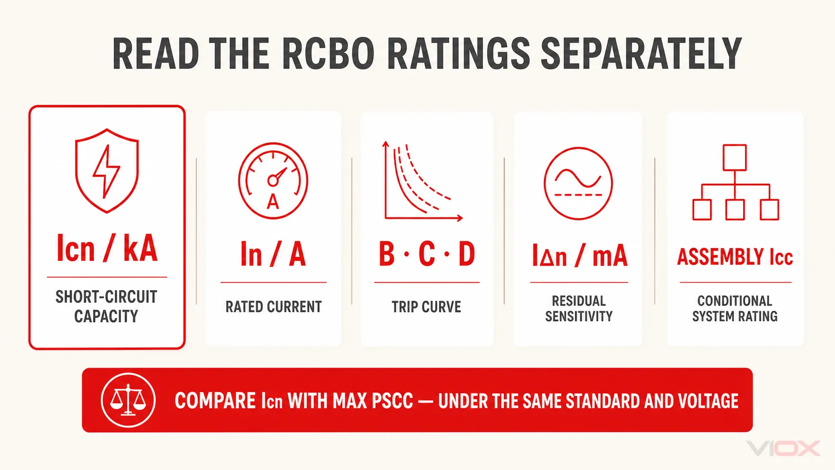
| Marking or concept | Controls | It does not prove |
|---|---|---|
| Icn / kA short-circuit capacity | The declared short-circuit interruption duty under the applicable product standard | Continuous load capacity, residual-current sensitivity, or trip curve |
| In, such as 20 A or 32 A | Rated current of the overcurrent function | Ability to interrupt a 6 kA, 10 kA, or 16 kA prospective fault |
| B, C, D, or another trip characteristic | The overcurrent tripping characteristic under its applicable standard | A different Icn unless the datasheet separately says so |
| IΔn, such as 30 mA | Rated residual operating current | Short-circuit breaking capacity |
| Assembly Icc or conditional short-circuit rating | A verified assembly or combination under stated conditions | The standalone Icn of every device inside the assembly |
Breaking capacity is not an “overload class.” Overload response and short-circuit interruption are related protection functions, but their markings answer different engineering questions. For a wider terminology crosswalk, use the VIOX guide to Icn, Icu, Ics, Icw, and Icm circuit-breaker ratings.
Four Inputs Required Before Choosing 6kA, 10kA, or 16kA
1. Maximum PSCC at the Exact Installation Point
PSCC is a property of the source and circuit at a location, not of the RCBO. It changes with supply impedance, transformer and network data, conductor impedance, and system configuration. A main board and a distant downstream board can therefore have different fault levels even in the same building.
Use a project-appropriate evidence source, such as:
- a utility-declared maximum fault level;
- a short-circuit study or documented design calculation;
- a verified upstream design value adjusted for the conductors and source configuration; or
- a competent measurement with a suitable installation tester and an accepted project method.
Fluke’s installation-tester documentation describes prospective short-circuit current as calculated from measured mains voltage divided by measured line impedance. That relationship is useful for understanding the variable, but it is not a do-it-yourself energized test instruction. Measurement method, instrument limits, system state, test point, and local rules must be controlled by a competent person. See the Fluke 1670 Series documentation.
2. System Voltage, Frequency, and Current Type
A kA figure is not automatically valid at every voltage or for both AC and DC. Use the datasheet row that matches the actual circuit. If the RCBO carries ratings under more than one standard, keep each value within its own test framework.
3. Applicable Product Standard and Market Acceptance
IEC 61009-1 is an RCBO product standard; it is not the installation code for every market. Verify the required national adoption, certification, approvals, and project specifications separately. An IEC declaration alone does not prove acceptance in a jurisdiction that requires another product standard or certification scheme.
4. Exact Backup, Cascading, or Assembly Evidence
An upstream fuse or circuit breaker can sometimes support a downstream protective device during a high fault, but the result depends on tested or manufacturer-declared behavior. Accept only documentation that identifies:
- the upstream device’s exact type, family, and rating;
- the downstream RCBO’s exact catalog number or covered range;
- the applicable voltage and current type;
- the maximum conditional short-circuit current;
- the enclosure, busbar, or assembly conditions when specified; and
- any limitation on poles, accessories, conductor arrangement, or installation method.
“There is an upstream breaker” is not coordination evidence.
RCBO Breaking-Capacity Selection Flow
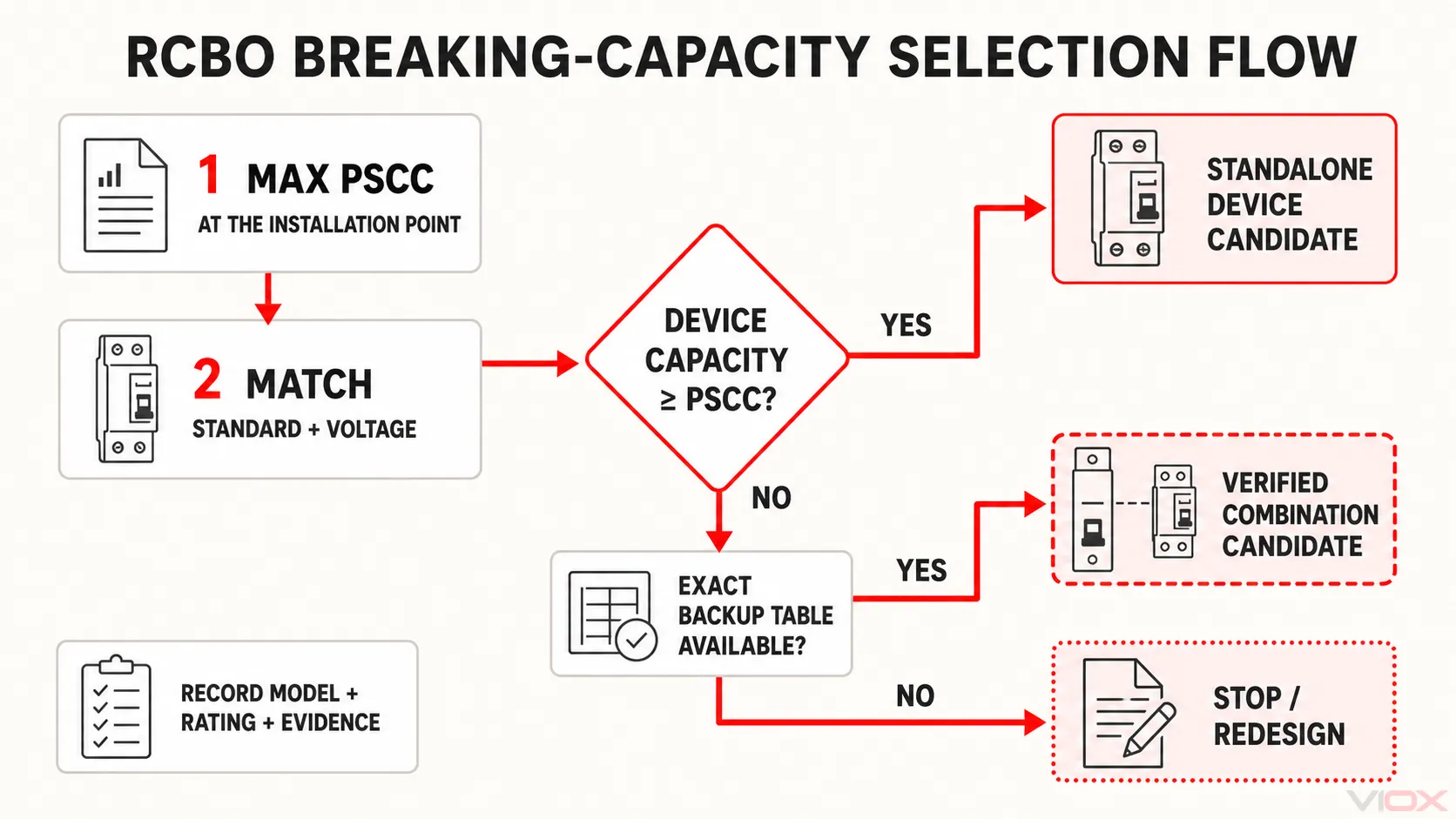
Use this sequence:
- Establish the maximum credible PSCC at the exact RCBO installation point under the operating configuration that produces the highest relevant value.
- Identify the candidate RCBO’s standard and applicable voltage. Reject a kA number carried over from a different standard, voltage, or current type.
- Compare like with like. For a standalone device, require the applicable declared short-circuit capacity to be at least the maximum PSCC.
- If the device alone is insufficient, check an exact documented combination. Do not infer backup protection from brand compatibility, an upstream ampere rating, or a generic product-family statement.
- Verify the assembly and procurement record. Record the selected model, rating basis, PSCC evidence, upstream combination where used, and document revision.
- Recalculate when the system changes. A transformer change, supply upgrade, parallel source, generator arrangement, cable change, or board relocation can change the available fault current.
This produces two defensible outcomes:
- Individual-device route: applicable RCBO capacity ≥ maximum PSCC.
- Verified-combination route: the exact upstream/downstream combination has a declared conditional capacity ≥ maximum PSCC under the documented conditions.
Anything else is an unresolved design input, not a selection.
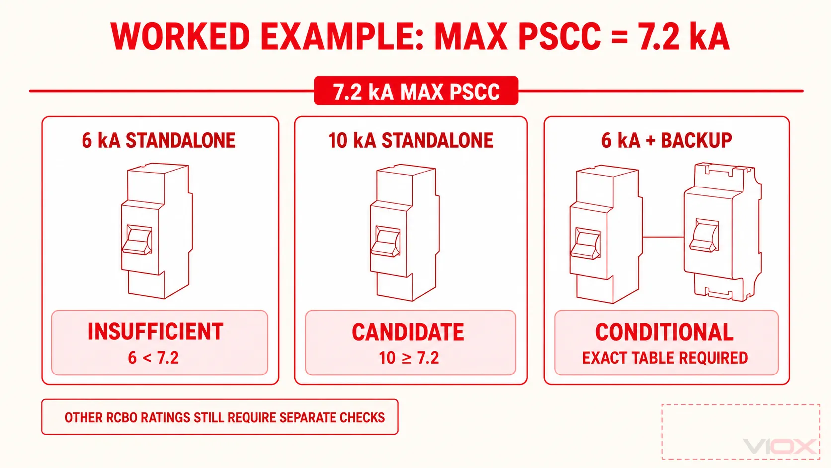
Worked Example: A 7.2kA Maximum PSCC
Assume a documented study gives a maximum PSCC of 7.2 kA RMS at the RCBO installation point. The circuit is AC at the voltage covered by the candidate datasheets, and the project requires an RCBO under the applicable IEC 61009-1 framework.
Candidate A: 6kA Standalone RCBO
The standalone device is insufficient because 6 kA is below 7.2 kA. Calling the installation residential or moving the product into a larger enclosure does not change that comparison.
Candidate B: 10kA Standalone RCBO
An exact model with an applicable 10 kA declaration can satisfy the short-circuit-capacity comparison because 10 kA is not less than 7.2 kA. The designer must still verify its other independent attributes—rated current, trip curve, residual-current type and sensitivity, poles, neutral arrangement, voltage, and market acceptance.
Candidate C: 6kA RCBO in a Verified Combination
It may be acceptable only if the manufacturer provides documentation for the exact upstream device and downstream RCBO showing a conditional short-circuit capacity of at least 7.2 kA at the project voltage and under the actual assembly conditions.
No generic percentage margin has been added. If the project requires allowance for network growth or uncertainty, define that in the fault-current study or project specification rather than inventing a universal multiplier in the RCBO article.
How to Verify a Claimed 16kA RCBO Solution
The phrase “16 kA RCBO” needs a document check. It can refer to different things:
- the individual RCBO’s declared short-circuit capacity under its product standard;
- a rating declared under a second standard or at a different voltage;
- a rated conditional short-circuit current for an RCBO protected by a specified upstream device; or
- an assembly rating for a consumer unit or distribution board.
For example, Eaton documentation for one consumer-unit system states a 16 kA rated conditional short-circuit current for the assembly while separately identifying the RCBO product standard. That is useful combination evidence for the documented system; it is not proof that an RCBO removed from that system has a standalone 16 kA Icn. See Eaton’s Memera EAS consumer-unit instructions.
Before accepting a 16 kA solution, ask:
- Which symbol is used: Icn, Icu, Ics, Icc, or another defined rating?
- Which standard and edition define it?
- At what voltage, frequency, and current type is it declared?
- Does it apply to the RCBO alone or only with a named upstream protective device?
- Is a specific enclosure, busbar, consumer unit, or distribution-board system required?
- Does the document cover the exact RCBO model and pole arrangement?
If those questions cannot be answered from the current technical file, the 16 kA claim is not yet a usable specification.
Procurement Specification and RFQ Checklist
Use this minimum output for a checkable enquiry:
| Required field | Record |
|---|---|
| Circuit and installation point | Board/circuit reference and physical point |
| Maximum PSCC | Value, RMS basis, source, date, and system configuration |
| System | AC/DC, voltage, frequency, phases, and earthing context where relevant |
| Product framework | Required RCBO standard, national adoption, approval, or certification |
| Short-circuit requirement | Minimum applicable standalone capacity, or conditional combination capacity |
| RCBO attributes | Poles, switched-neutral requirement, In, trip curve, IΔn, and residual-current type |
| Combination evidence | Exact upstream and downstream catalog numbers, document/table reference, voltage, and conditions |
| Assembly evidence | Enclosure or board designation and assembly rating when the solution depends on it |
| Change control | Design revision and trigger for recalculation |
This checklist deliberately separates the breaking-capacity decision from the rest of RCBO selection. For the other attributes, use How to Select the Right RCBO. For broader orientation, start at What Is an RCBO?.
Common RCBO Breaking-Capacity Selection Errors
- Selecting by building type. Commercial sites can have low PSCC and homes can have high PSCC; the installation-point value controls the decision.
- Reading 32 A as fault capacity. Rated current and kA capacity answer different questions.
- Treating B, C, or D as the kA rating. Trip characteristic does not replace the short-circuit-capacity declaration.
- Using transformer distance as a rule. Distance affects impedance, but conductor material, size, route, transformer data, and network configuration are also required.
- Copying an Icu or Ics value into an Icn specification. Keep ratings within the standard and voltage that define them.
- Assuming higher kA means better residual-current protection or longer life. Those claims require separate evidence; the kA choice is made against short-circuit duty.
- Claiming backup protection without the table. A plausible upstream device is not the same as a verified combination.
- Confusing an assembly’s 16 kA conditional rating with every RCBO’s standalone capacity. Record the assembly and upstream-device conditions.
Frequently Asked Questions
Is a 10kA RCBO always better than a 6kA RCBO?
It has a higher declared short-circuit capacity when the compared ratings use the same applicable standard and voltage. That does not make its rated current, trip curve, residual-current type, sensitivity, fit, or approval automatically better for the circuit.
Can I use a 6kA RCBO where PSCC is exactly 6kA?
The basic comparison is satisfied when the applicable 6 kA declaration is not less than the verified maximum PSCC. The project must still address measurement or calculation uncertainty, local rules, exact device data, and any required assembly conditions. Do not create a universal article-level margin to replace those engineering inputs.
Does an upstream fuse make every 6kA RCBO suitable for 16kA?
No. Use only a manufacturer-documented combination that covers the exact fuse or breaker, RCBO, voltage, and installation conditions. Backup protection is combination-specific.
Can I calculate PSCC from voltage and impedance?
The simplified relationship is current equals voltage divided by impedance, and installation testers can derive PSC from measured voltage and line impedance. A valid project result still depends on the correct fault path, method, instrument, system state, and competent interpretation.
Are 5kA and 6kA RCBOs the same class?
No. They are different declared values, and the exact model data controls. Do not group them as one “5/6 kA class” when comparing against PSCC.
Primary Technical Sources
Once the fault-current requirement and the other RCBO attributes are defined, evaluate the VIOX RCBO range or send the completed checklist to [email protected]. Request the exact product datasheet and any combination table needed for the proposed assembly; do not rely on a family-level marketing label.