
Direct Answer
A distribution box is a low-voltage electrical enclosure that receives incoming power and distributes it safely to multiple outgoing circuits through protective and switching devices such as MCBs, RCDs, RCBOs, fuses, isolators, busbars, neutral bars, earth bars, and surge protective devices.
The right distribution box is selected by:
- Application: residential, commercial, industrial, outdoor, temporary power, solar, or machinery.
- Supply system: single-phase, three-phase, AC, DC, TN, TT, IT, or local earthing system.
- Number of outgoing circuits: current circuits plus spare ways for future expansion.
- Protective-device strategy: MCB, RCCB, RCBO, fuse, SPD, AFDD, isolator, or main breaker.
- Rated current and short-circuit capacity: based on actual load and available fault current.
- Internal layout: busbar type, neutral bar arrangement, earth bar, DIN rail space, wiring room, cable entries, and heat dissipation.
- Enclosure protection: IP rating, material, UV resistance, corrosion resistance, impact protection, and mounting method.
- Standards and local code: IEC 61439, IEC 60670, IEC 60898, IEC 61008, IEC 61009, IEC 61643, UL/NEC, BS 7671, or other regional requirements.
The most common selection mistake is choosing the box only by the number of ways. A 12-way box with weak busbar compatibility, poor neutral-bar arrangement, no SPD space, inadequate short-circuit rating, or insufficient cable room can be a worse choice than a larger, better-designed 18-way box.
Key Takeaways
- A distribution box is not just an empty plastic or metal enclosure. It is an electrical assembly where protection, isolation, power distribution, neutral return, earthing, and surge protection must work together.
- The internal structure determines safety as much as the outside enclosure rating.
- MCBs protect against overload and short-circuit current; they do not replace RCD/RCBO shock protection.
- Busbars distribute phase conductors to multiple protective devices, but compatibility with the breaker family is critical.
- Neutral bars and earth bars must be arranged according to the protection scheme; mixed neutrals downstream of RCDs are a common fault source.
- SPDs should be placed and wired to minimize lead length and coordinate with the earthing system.
- IEC 61439-3 applies to distribution boards intended to be operated by ordinary persons, while IEC 60670-24 applies to certain enclosures for housing protective devices in household and similar fixed installations.
- The best distribution box is selected by load, protection, environment, expansion, and compliance, not by price or way count alone.
What Is a Distribution Box?
A distribution box, also called a distribution board, DB box, breaker box, consumer unit, load centre, or panelboard depending on region, is the point where electrical power is divided into individual branch circuits.
In a typical low-voltage installation, it performs five jobs:
- Distribution: splits the incoming supply into outgoing circuits.
- Protection: disconnects faulty circuits through breakers, fuses, RCDs, RCBOs, or other devices.
- Isolation: provides a way to disconnect the supply for maintenance or emergency use.
- Connection: organizes live, neutral, and protective earth conductors.
- Containment: protects people from live parts and protects components from dust, moisture, impact, and environmental stress.
The exact name depends on the market. A UK domestic board is usually called a consumer unit. A North American residential board may be called a load center. In IEC industrial and commercial work, distribution board or distribution box is more common.
For adjacent terminology, Electrical Enclosure vs Distribution Box vs Distribution Board explains the naming boundary, while Distribution Boxes vs Combiner Boxes is useful when comparing building distribution with solar combiner applications.
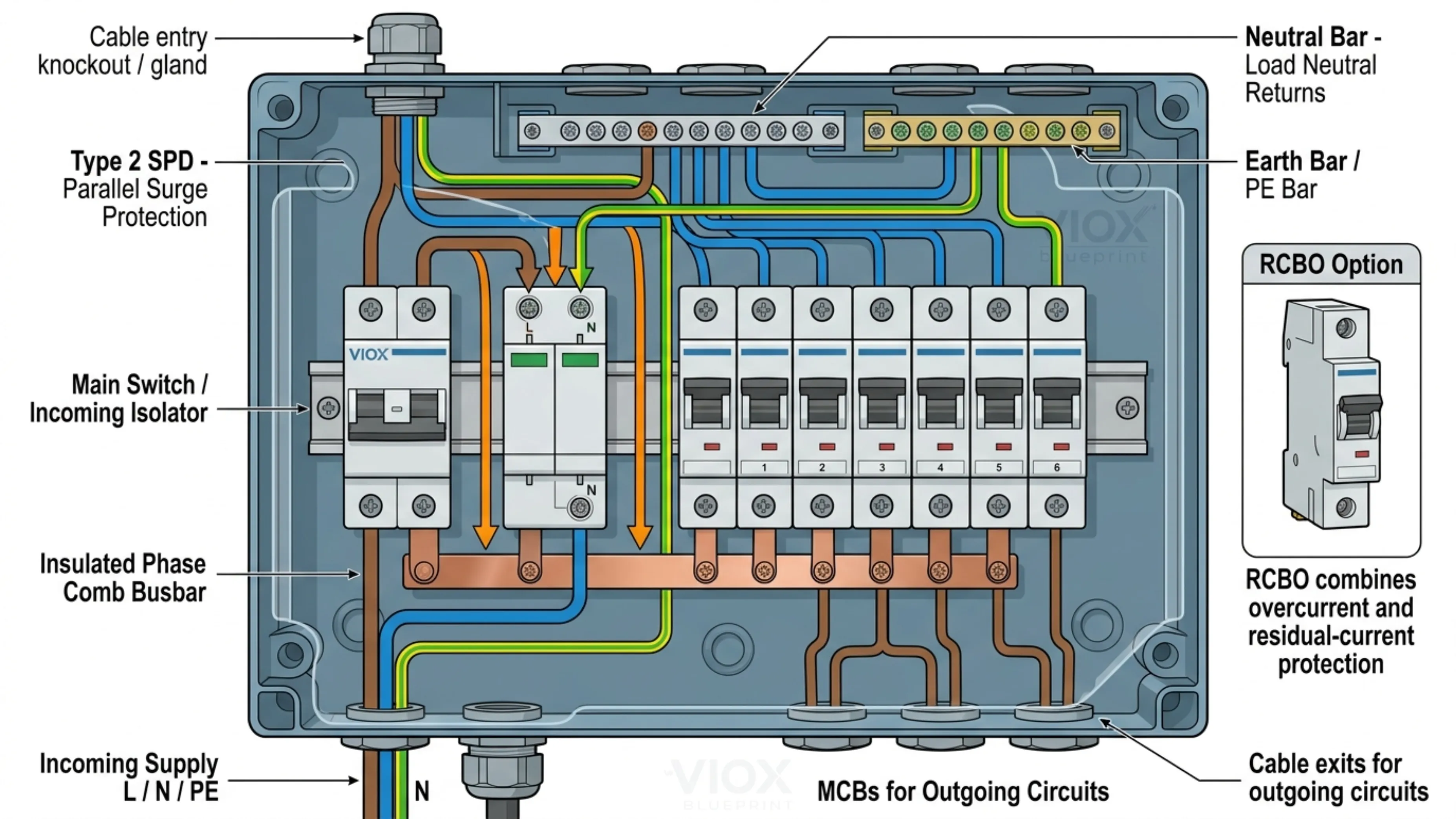
Distribution Box Internal Structure Diagram: MCBs, Busbars, Neutral Bars, and SPDs Explained
The internal structure of a distribution box is where many selection and installation errors happen. The outside may look like a simple enclosure, but inside it there are multiple current paths and protection layers.
Below is a simplified internal structure diagram for a typical single-phase AC distribution box using an incoming main switch, SPD, MCBs, neutral bar, and earth bar. Actual wiring varies by region, earthing system, RCD/RCBO strategy, and manufacturer instructions.
             Incoming Supply
          L        N        PE
          |        |        |
          |        |        +--------------------+
          |        |                             |
          v        v                             v
   +-----------------------+              +--------------+
   | Main Switch/Isolator  |              | Earth Bar PE |
   +-----------------------+              +--------------+
          |        |                             |
          |        |                             |
          |        +------------+                |
          |                     |                |
          v                     v                |
   +--------------+      +--------------+        |
   | Phase Busbar |      | Neutral Bar  |        |
   +--------------+      +--------------+        |
      |   |   |             |   |   |            |
      v   v   v             v   v   v            |
   +----+----+----+      N1  N2  N3              |
   |MCB |MCB |MCB |                               |
   +----+----+----+                               |
      |   |   |                                   |
      v   v   v                                   |
   Outgoing Circuits                              |
      L1  L2  L3                                  |
                                                  |
   +-------------------+                          |
   | SPD Module        |--------------------------+
   | L/N to PE or N-PE |
   +-------------------+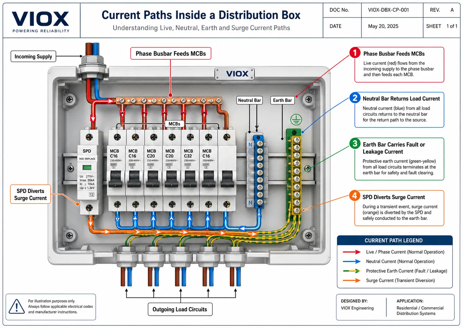
This diagram is simplified, but it shows the functional logic:
- the incoming live conductor feeds the main switch
- the main switch feeds the phase busbar
- the busbar distributes live supply to MCBs or RCBOs
- outgoing live conductors leave through protective devices
- outgoing neutral conductors return to the appropriate neutral bar
- protective earth conductors terminate on the earth bar
- the SPD is connected between live/neutral conductors and earth to divert transient overvoltage
1. Main Switch or Incoming Isolator
The main switch disconnects the distribution box from the incoming supply. In small residential boards, this may be a double-pole main switch. In three-phase boards, it may be a four-pole switch disconnector, main MCCB, or other incoming device.
Selection checks:
- rated voltage
- rated current
- pole configuration
- short-circuit withstand or conditional rating
- isolation function
- compatibility with the enclosure
- lockable OFF function if required
The main switch is not necessarily the same thing as a circuit breaker. A switch disconnector provides isolation but may not provide overcurrent protection unless specifically designed and rated for that function.
2. MCBs: Outgoing Circuit Protection
Miniature circuit breakers (MCBs) protect outgoing circuits against overload and short-circuit current. Each outgoing circuit should be matched to the conductor size, installation method, load type, and applicable wiring rules.
In a distribution box, MCB selection depends on:
- current rating
- curve type
- number of poles
- breaking capacity
- voltage rating
- busbar compatibility
- terminal capacity
- installation environment
An MCB does not provide residual-current shock protection. Where leakage-current protection is required, an RCCB, RCD, or RCBO strategy must be added.
For component background, see What Is a Miniature Circuit Breaker? and How to Choose the Right Miniature Circuit Breaker.
3. RCDs, RCCBs, and RCBOs
Residual-current protection detects current imbalance between live and neutral conductors. It is used to reduce electric-shock risk and, in some applications, fire risk caused by earth leakage.
Common arrangements include:
- RCCB plus MCBs: one residual-current device protects several MCB circuits.
- RCBO per circuit: each circuit has combined overcurrent and residual-current protection.
- Split-load board: circuits divided across two or more RCD groups.
- High-integrity board: selected critical circuits may use separate RCBOs.
RCBO-based layouts often provide better fault selectivity because one earth fault does not disconnect multiple unrelated circuits. However, cost, space, local regulation, leakage current, and circuit criticality also matter.
When upgrading or selecting a protection strategy, RCBO vs MCB explains why overcurrent protection and residual-current protection solve different problems.
4. Phase Busbar
The phase busbar distributes live supply from the main switch or RCD to multiple protective devices. It may be a pin-type, fork-type, comb busbar, copper link, or manufacturer-specific assembly.
Busbar quality and compatibility matter because poor busbar contact can cause heating, nuisance tripping, or fire risk.
Selection checks:
- rated current
- number of phases
- pin or fork type
- spacing and pitch
- insulation
- compatibility with MCB/RCBO series
- end caps and covers
- short-circuit withstand
- tightening torque
- manufacturer-approved use
Do not assume every busbar fits every breaker. Similar-looking MCBs can have different terminal geometry and busbar requirements. MCB Busbar Compatibility Guide and Pin-Type Busbar vs Fork-Type Busbar cover this boundary in more detail.
5. Neutral Bar
The neutral bar provides termination points for outgoing neutral conductors. Its arrangement is simple only in the most basic boards.
In RCD or RCBO layouts, neutral routing is critical:
- neutrals downstream of one RCD must return to that same RCD’s neutral bar
- neutrals from different RCD groups must not be mixed
- RCBO circuits usually require their own neutral routing according to device instructions
- shared or borrowed neutrals can cause unwanted tripping or dangerous fault conditions
Incorrect neutral-bar wiring is one of the most common reasons a newly installed board trips immediately.
For the safety boundary between neutral and protective earth, see Neutral Bar vs Grounding Bar and Neutral Bar Shock Safety.
6. Earth Bar or Grounding Bar
The earth bar provides termination for protective earth conductors. In a fault, the protective earth path helps create a current path that allows protective devices to disconnect the supply.
It also provides a reference point for:
- protective bonding
- metal enclosure earthing
- SPD discharge path
- equipment protective conductors
- cable gland bonding, where required
The earth bar must be mechanically secure, correctly sized, and connected to the installation earthing system according to local rules.
7. Surge Protective Device (SPD)
An SPD limits transient overvoltage from lightning-induced surges, switching transients, or supply disturbances. In a distribution box, it is normally installed near the incoming supply side, with short connections to live, neutral, and earth paths.
SPD selection depends on:
- Type 1, Type 2, or Type 3 application
- system voltage
- earthing system
- Uc or maximum continuous operating voltage
- Up or voltage protection level
- In and Imax discharge-current ratings
- backup protection
- lead length
- installation location
SPD wiring layout matters. Long leads add inductive voltage during fast surge events, reducing effective protection. In an upgraded distribution box, the SPD position should be planned before the board is filled with breakers and wiring.
For SPD fundamentals, see What Is a Surge Protection Device?, What Do Uc and Up Mean on an SPD?, and Where to Install SPDs in an Electrical Panel.
8. DIN Rail, Terminal Blocks, Cable Entries, and Covers
The mechanical structure determines whether the board is easy and safe to wire.
Check:
- DIN rail strength and alignment
- terminal capacity
- cable bending space
- cable gland or knockout layout
- separation between incoming and outgoing wiring
- cover and dead-front design
- IP rating after cable entry
- heat dissipation path
- labelling space
A distribution box that is too cramped may pass visual inspection when empty but become hard to terminate safely once real conductors are installed.
Distribution Box Components at a Glance
| Component | Main role | Selection risk |
|---|---|---|
| Enclosure | Protects internal parts and users | Wrong IP rating, weak material, poor UV or corrosion resistance |
| Main switch | Isolates the board | Underrated current or wrong pole configuration |
| MCB | Overload and short-circuit protection | Wrong curve, breaking capacity, or conductor match |
| RCCB/RCD | Residual-current protection | Wrong sensitivity, type, or neutral routing |
| RCBO | Combined MCB and RCD protection per circuit | More cost and space, but better selectivity |
| Busbar | Feeds multiple protective devices | Incompatible pitch or terminal geometry |
| Neutral bar | Terminates return conductors | Mixed neutrals causing RCD/RCBO faults |
| Earth bar | Terminates protective conductors | Poor bonding or undersized earth path |
| SPD | Limits transient overvoltage | Wrong Uc, Up, type, or lead length |
| Cable glands/entries | Maintains enclosure integrity | IP rating lost after poor cable entry |
| Labels | Identify circuits and devices | Unsafe isolation during maintenance |
How to Choose the Right Distribution Box
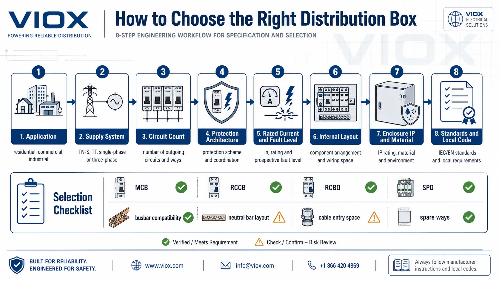
Step 1: Define the application
Start with the installation type.
| Application | Typical priority |
|---|---|
| Residential | compact size, RCD/RCBO protection, safe user operation |
| Commercial | more circuits, clear labelling, serviceability, load diversity |
| Industrial | higher fault level, three-phase loads, thermal management |
| Outdoor | IP rating, UV resistance, corrosion resistance |
| Temporary power | mechanical strength, socket outlets, portability, weather protection |
| Solar or storage | AC/DC separation, SPD strategy, inverter connection, isolation |
| EV charging | load calculation, RCD type, SPD, dedicated circuit protection |
The same “12-way distribution box” description is not enough. A 12-way indoor lighting board and a 12-way outdoor pump control distribution box are different products in practice.
Step 2: Confirm supply type and earthing system
Before choosing the box, confirm:
- single-phase or three-phase
- AC or DC
- supply voltage
- maximum demand
- earthing system
- prospective short-circuit current
- neutral arrangement
- main protective bonding requirements
The internal layout of the distribution box must match this system. A three-phase board requires a different busbar and phase arrangement from a single-phase board. TT systems may impose different RCD requirements than TN systems. DC distribution boxes require DC-rated protective devices and isolation, not AC-only parts.
For AC/DC selection context, see AC Distribution Box vs DC Distribution Box.
Step 3: Count circuits and spare ways correctly
Do not select a distribution box by the current number of circuits only.
Count:
- lighting circuits
- socket circuits
- HVAC circuits
- motor loads
- water heater or cooker circuits
- EV charger circuits
- solar inverter or battery circuits
- outdoor circuits
- control circuits
- dedicated equipment circuits
- spare ways for future expansion
A practical selection rule is to leave enough spare ways for future additions. The exact margin depends on the project, but a board filled on day one usually becomes expensive to modify later.
Step 4: Select protection architecture
Choose the protective-device strategy before choosing the enclosure size.
Common options:
- main switch plus MCBs
- main RCCB plus MCBs
- dual-RCD split-load arrangement
- full RCBO arrangement
- main MCCB plus outgoing MCBs
- fuse switch plus distribution blocks
- SPD-integrated layout
- AFDD/RCBO layout where required
The architecture affects neutral bars, busbars, enclosure depth, heat dissipation, and wiring room.
Step 5: Verify rated current and short-circuit capacity
A distribution box must be rated for the current and fault conditions at the installation point.
Check:
- rated current of the assembly
- rated voltage
- incoming device rating
- outgoing device ratings
- busbar rating
- conditional short-circuit rating
- breaking capacity of MCBs or MCCBs
- upstream protective device coordination
Do not rely only on the breaker current printed on the front. The assembly rating depends on the enclosure, busbar, heat rise, and tested configuration.
Step 6: Select enclosure material and IP rating
The enclosure must match the environment.
| Environment | Common concern |
|---|---|
| Indoor dry area | touch protection, cable entry, neat installation |
| Outdoor wall | rain, UV, temperature cycling |
| Dusty workshop | dust ingress and cleaning access |
| Coastal area | corrosion and salt mist |
| Food or washdown area | water jets and chemical exposure |
| Industrial floor | impact, vibration, heat, cable management |
Plastic enclosures may be suitable for many indoor or outdoor applications when correctly rated. Metal enclosures may be preferred for impact, fire containment, shielding, or specific regional requirements. Stainless steel or fiberglass may be needed in corrosive environments.
For enclosure material choice, see Electrical Enclosure Material Selection Guide and Weatherproof vs Standard Junction Box Guide.
Step 7: Check heat rise and internal space
Distribution boxes generate heat through protective devices, busbars, terminals, and conductors. Overcrowding reduces airflow and increases conductor stress.
Check:
- number of adjacent loaded MCBs
- continuous load level
- internal ambient temperature
- enclosure ventilation
- cable grouping
- heat from SPDs and electronic devices
- manufacturer derating information
- space around busbars and terminals
Heat problems often appear later, after additional circuits are added. MCB Busbar Overheating shows why internal connection quality and thermal layout cannot be treated as minor details.
Step 8: Verify standards and approvals
Applicable standards depend on product type and region.
| Standard | Relevance |
|---|---|
| IEC 61439-1 | General rules for low-voltage switchgear and controlgear assemblies |
| IEC 61439-3 | Distribution boards intended to be operated by ordinary persons |
| IEC 60670-24 | Enclosures for housing protective devices and other power-dissipating equipment in household and similar fixed installations |
| IEC 60898-1 | MCBs for household and similar installations |
| IEC 61008 | RCCBs without integral overcurrent protection |
| IEC 61009 | RCBOs with integral overcurrent protection |
| IEC 61643-11 | Low-voltage surge protective devices |
| UL 67 / UL 489 / NEC | Common North American panelboard and breaker context |
| BS 7671 | UK wiring rules for electrical installations |
Do not claim that a distribution box assembly complies with a standard simply because individual devices inside it are certified. IEC 61439 treats the complete assembly as the object of verification.
Selection Checklist
Before buying or specifying a distribution box, collect these values:
| Required information | Why it matters |
|---|---|
| Supply voltage and phase | Determines box type and protective-device layout |
| Earthing system | Determines RCD/SPD strategy and neutral-earth arrangement |
| Maximum demand | Determines incoming current rating and heat rise |
| Available fault current | Determines breaking capacity and short-circuit rating |
| Number of circuits | Determines ways and enclosure size |
| Future expansion | Avoids immediate overcrowding |
| Indoor/outdoor environment | Determines IP rating and material |
| Protective device type | Determines busbar, neutral bar, and wiring layout |
| SPD requirement | Determines space, wiring length, and backup protection |
| Cable size and entry direction | Determines enclosure depth and knockout/gland layout |
| Local standard | Determines compliance route and inspection expectations |
Common Selection Mistakes
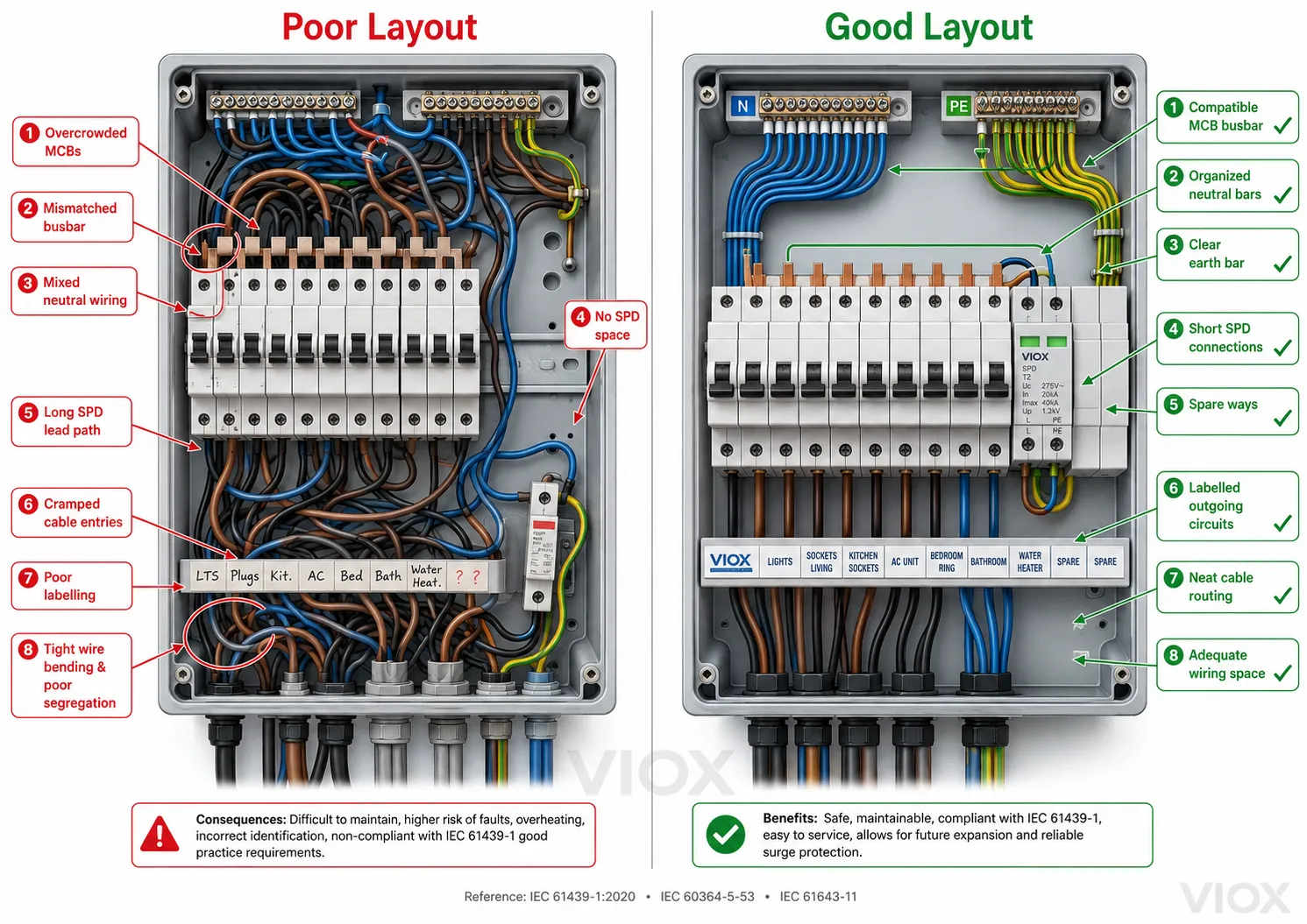
Mistake 1: Choosing by number of ways only
Way count does not tell you busbar capacity, enclosure depth, neutral-bar layout, short-circuit rating, or SPD space.
Mistake 2: Mixing MCBs and busbars from incompatible families
Similar-looking devices may not have the same terminal geometry. A poor busbar fit can overheat.
Mistake 3: Ignoring neutral-bar design
In RCD and RCBO layouts, wrong neutral routing causes nuisance tripping and unsafe fault diagnosis.
Mistake 4: Adding an SPD after the board is already full
SPD performance depends on location and lead length. It should be planned in the original layout.
Mistake 5: Using indoor boxes outdoors
Outdoor boxes need suitable IP rating, UV resistance, corrosion resistance, and cable-entry sealing.
Mistake 6: Treating the enclosure as the only safety feature
The enclosure protects access and environment, but electrical safety also depends on protective devices, busbars, terminals, earthing, and testing.
Mistake 7: Ignoring heat dissipation
Continuous loads, dense breaker rows, and poor ventilation can create temperature-rise problems even when each individual component appears correctly rated.
Mistake 8: Copying regional load calculations blindly
Load-calculation rules differ by country and code. A NEC-style residential calculation should not be inserted into an IEC or BS distribution-board selection guide without clearly marking its region.
FAQ
What is inside a distribution box?
A distribution box may contain a main switch or main breaker, MCBs, RCCBs, RCBOs, fuses, busbars, neutral bars, earth bars, SPDs, DIN rails, terminal blocks, cable entries, and circuit labels. The exact layout depends on the supply system and protection strategy.
What is the difference between a distribution box and a distribution board?
In many markets, the terms overlap. A distribution board usually refers to the complete electrical assembly for distributing circuits. A distribution box may refer to a smaller enclosed board or protective-device enclosure. Local terminology varies.
What is the purpose of a busbar in a distribution box?
The busbar distributes live supply from the incoming device or RCD to multiple outgoing protective devices. It must match the current rating, phase arrangement, and MCB/RCBO terminal geometry.
What is the neutral bar used for?
The neutral bar terminates outgoing neutral conductors and provides the return path for circuit current. In RCD and RCBO boards, neutral routing must match the protective-device arrangement.
Is the earth bar the same as the neutral bar?
No. The neutral bar carries return current during normal operation. The earth bar connects protective conductors and normally carries current only during fault or leakage conditions. Their connection rules depend on the earthing system and local code.
Do I need an SPD in a distribution box?
It depends on the installation standard, risk assessment, equipment sensitivity, and supply conditions. SPDs are increasingly common in modern boards to limit transient overvoltage. Selection must consider SPD type, Uc, Up, In, Imax, earthing system, and installation lead length.
How many ways should a distribution box have?
Count current circuits and add spare capacity for future expansion. Also consider whether RCBOs, SPDs, contactors, timers, or special devices require additional module space.
Can I mix different brands of MCBs in one distribution box?
Only if the assembly manufacturer permits it and compatibility is verified. Mixing devices can affect busbar fit, heat rise, short-circuit performance, and assembly verification.
What IP rating should an outdoor distribution box have?
The correct IP rating depends on exposure to rain, dust, water jets, sunlight, and installation position. Outdoor applications commonly need a weatherproof enclosure, but the exact rating must match the environment and local rules.
What standard applies to distribution boxes?
For IEC markets, IEC 61439-1 and IEC 61439-3 are central for low-voltage distribution assemblies intended for ordinary persons. IEC 60670-24 applies to certain enclosures for housing protective devices in household and similar fixed installations. Other regional standards may apply.
Sources Reviewed
- IEC 61439-1:2020 – Low-voltage switchgear and controlgear assemblies, general rules
- IEC 61439-3:2024 – Distribution boards intended to be operated by ordinary persons
- BS EN IEC 61439-3:2024 – Distribution boards intended to be operated by ordinary persons
- IEC 60670-24:2024 – Enclosures for housing protective devices
- IEC 60898-1 – Circuit-breakers for household and similar installations
- IEC 61008-1 – RCCBs without integral overcurrent protection
- IEC 61009-1 – RCBOs with integral overcurrent protection
- IEC 61643-11 – Low-voltage surge protective devices
