On this page
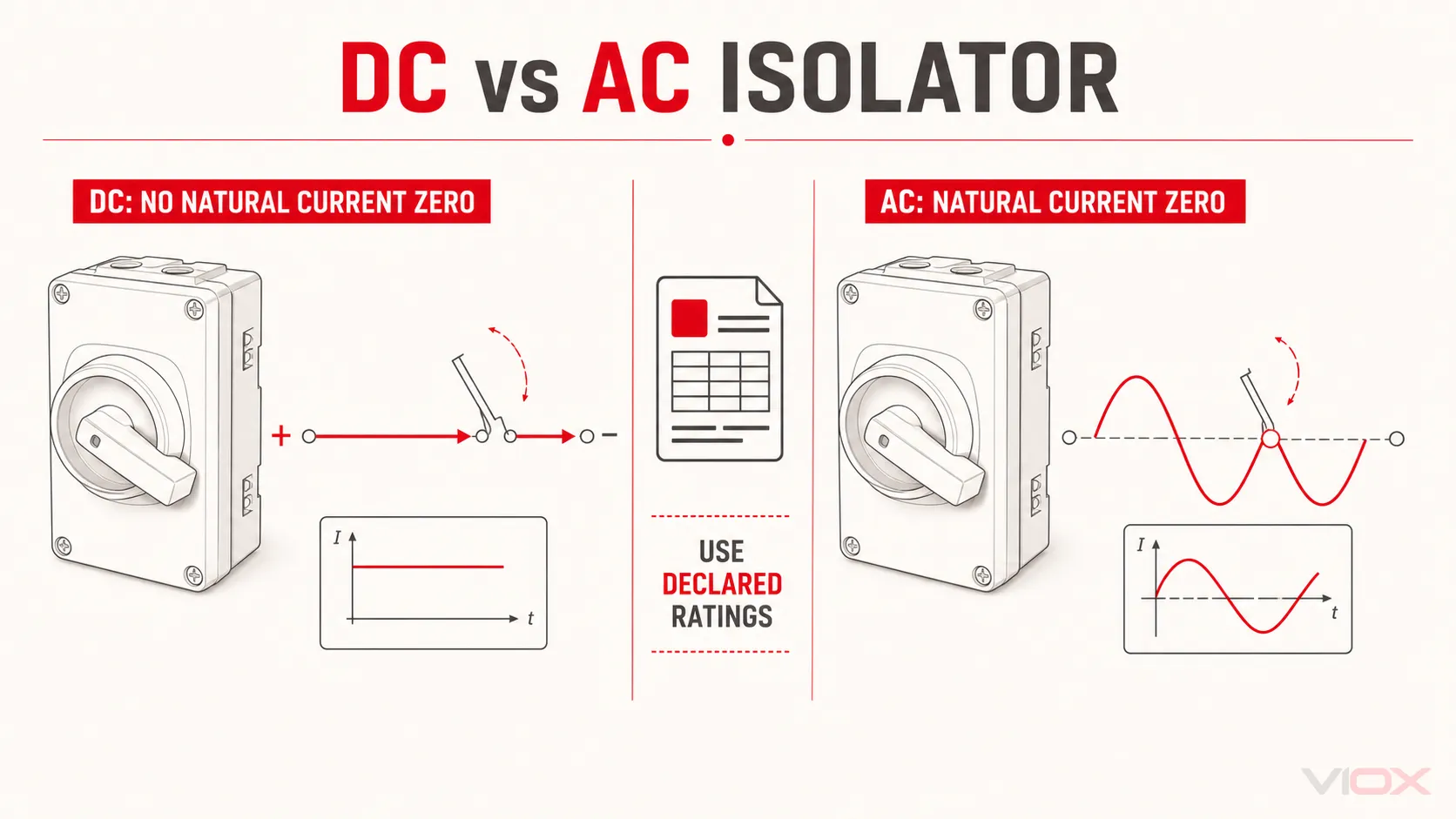
AC and DC isolator switches serve the same basic purpose: they create an isolation point so equipment can be separated from its source. Their electrical ratings, however, are not interchangeable.
Use a device on a DC circuit only when the manufacturer explicitly declares a suitable DC operational voltage, current, utilization category, and required pole or wiring arrangement. An AC voltage printed on the label cannot be converted into a safe DC rating with a universal ratio. The reverse is also true: a DC rating does not automatically establish suitability for an AC application.
The practical decision rule is simple:
Match the device to the current type, system voltage, load duty, pole arrangement, and manufacturer instructions. If the required AC or DC rating is absent, treat the device as unsuitable for that application.
DC vs AC Isolator Switch at a Glance
| Decision factor | AC isolator or switch-disconnector | DC isolator or switch-disconnector |
|---|---|---|
| Intended circuit | Alternating-current circuits | Direct-current circuits |
| Arc behavior when contacts open | Alternating current passes through natural current zeroes, which assist arc extinction | Direct current has no natural current zero-crossing, so interruption is generally more demanding |
| Acceptable rating evidence | Explicit AC operational voltage, current, frequency, and utilization category | Explicit DC operational voltage, current, utilization category, and any required polarity or pole configuration |
| Typical utilization categories under IEC 60947-3 | AC-20, AC-21, AC-22, or AC-23, with A/B operation suffix where declared | DC-20, DC-21, DC-22, or DC-23; some PV products also declare application-specific DC-PV categories |
| Pole arrangement | Selected for the AC system, phases, neutral treatment, and local rules | May require contacts or poles in series and a specific positive/negative connection arrangement defined by the manufacturer |
| Common applications | AC distribution, HVAC equipment, motors, and industrial machinery | Solar photovoltaic arrays, battery energy storage, DC distribution, and other DC systems |
| Can it be used on the other current type? | Only if the same product has a separate, adequate DC declaration | Only if the same product has a separate, adequate AC declaration |
This comparison is about electrical suitability, not the color or external appearance of the enclosure. Two rotary isolators can look almost identical while carrying very different operational ratings.
If you first need the device’s basic function and its place in a photovoltaic system, read what a DC isolator switch does. This page focuses specifically on the AC-versus-DC decision.
The Six-Check Interchangeability Test
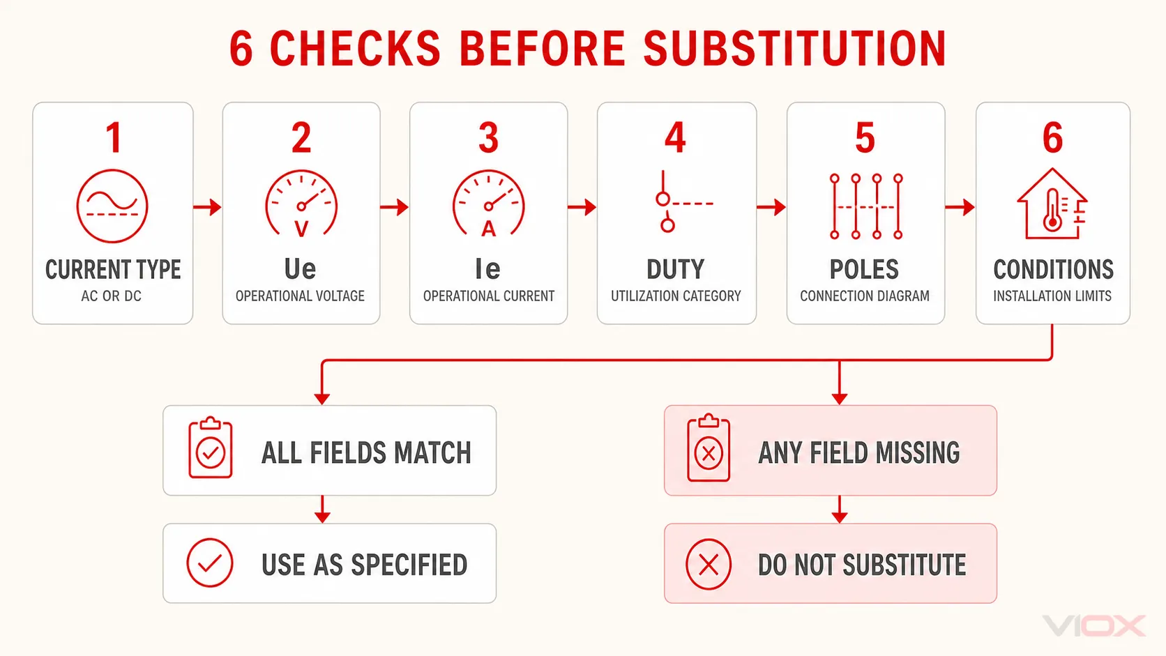
Before substituting one isolator for another, check all six items below. A pass on only voltage or current is not enough.
| Check | What to find on the label or datasheet | Reject the substitution when… |
|---|---|---|
| 1. Current type and operational voltage | A declared rated operational voltage, Ue, for AC or DC at the actual system voltage | The device shows only an AC value for a DC circuit, only a DC value for an AC circuit, or an inadequate voltage |
| 2. Operational current | Rated operational current, Ie, at that voltage and duty | The current value belongs to another voltage, category, temperature, or wiring configuration |
| 3. Utilization category | AC-20/21/22/23 or DC-20/21/22/23, including the A or B suffix where applicable | The category does not permit the intended load-making or load-breaking duty |
| 4. Device function | Whether it is a disconnector, switch, or switch-disconnector | A no-load disconnector is being treated as a device for normal load switching |
| 5. Poles and connection diagram | Required number of poles, series-contact arrangement, polarity, terminal assignment, and permitted circuit configuration | The proposed wiring differs from the manufacturer’s tested arrangement |
| 6. Installation conditions | Temperature derating, enclosure/IP declaration, pollution or altitude limits, short-circuit coordination, and applicable product approval | Any environmental, coordination, or market requirement is unsupported |
Quick accept-or-reject matrix
| Product declaration | Proposed use | Decision |
|---|---|---|
| AC rating only | AC circuit within all declared limits | Potentially suitable; verify duty and installation conditions |
| AC rating only | DC circuit | Reject—there is no declared DC capability |
| DC rating only | DC circuit within all declared limits | Potentially suitable; verify duty, poles, polarity, and installation conditions |
| DC rating only | AC circuit | Reject unless a separate AC rating is also declared |
| Separate AC and DC ratings | Either circuit | Use only within the rating and configuration declared for that current type |
| Voltage/current shown without clear current type or duty | AC or DC circuit | Do not assume suitability; obtain the manufacturer’s technical documentation |
A dual-rated product can therefore be used in either type of circuit, but it is not used under one universal rating. The permitted AC and DC values may differ, and the DC configuration may use a different number of poles or connection scheme.
Why Switching DC Is Generally More Demanding
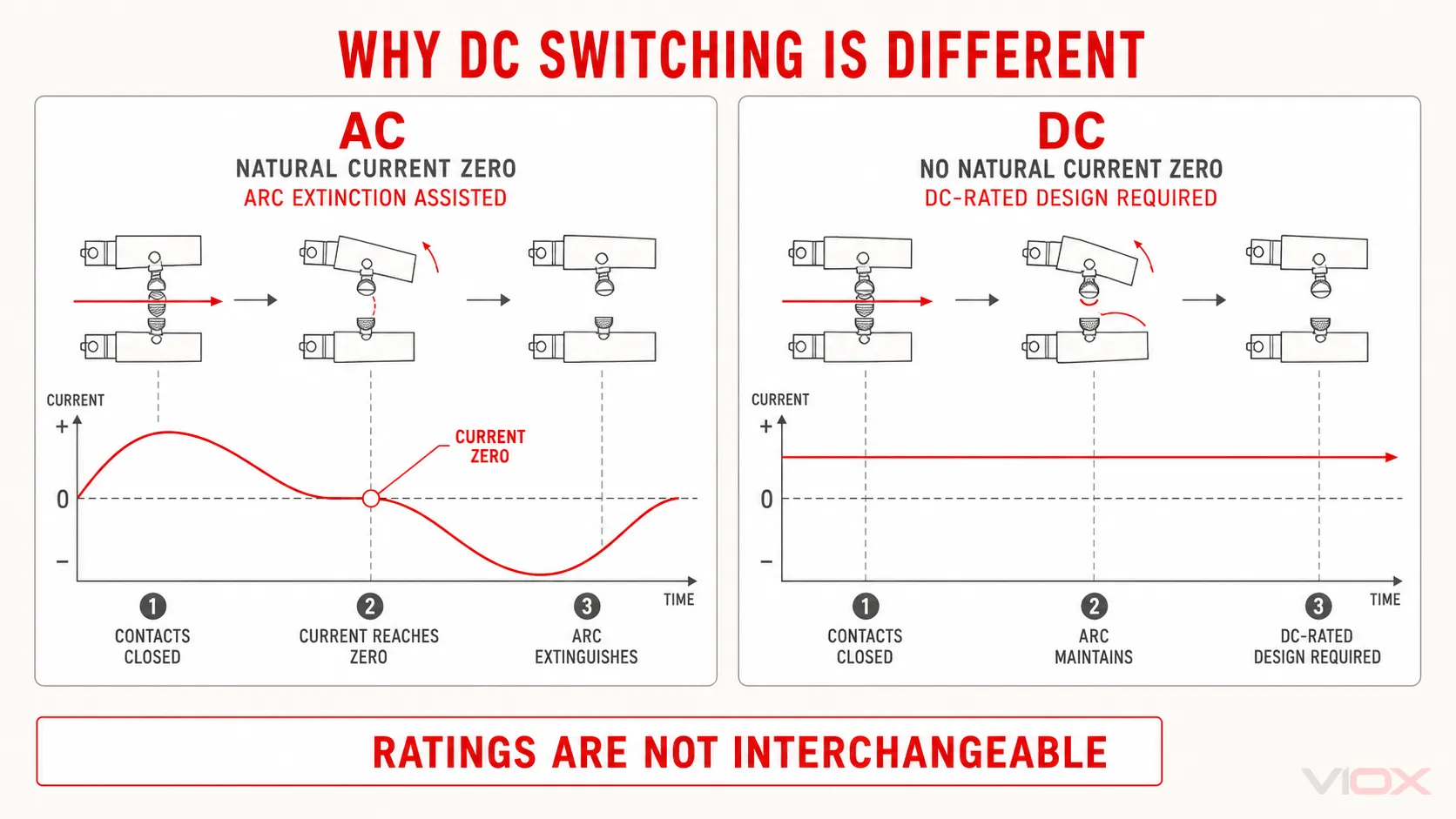
When mechanical contacts separate while current is flowing, an electrical arc can form across the opening gap. In an AC circuit, current reverses direction and passes through zero every half-cycle. That natural current zero assists interruption because the energy sustaining the arc periodically falls to zero.
DC current does not provide the same natural interruption point. As Schneider Electric explains in its low-voltage DC guidance, the absence of current and voltage zero-crossing makes the DC arcing time longer and increases the energy that the switching device must manage. Omron consequently advises selecting a switch with a declared DC rating when interrupting a DC circuit.
Manufacturers address DC interruption in different ways. Product design may involve contact geometry, opening speed, arc-control components, series-connected contacts, polarity-dependent arrangements, or combinations of these measures. It is not technically sound to assume that every DC isolator must contain one particular internal component.
The external handle also does not reveal the tested duty. The manufacturer’s AC or DC operational rating and connection diagram are the evidence that matters.
Is It a Disconnector or a Switch-Disconnector?
The word “isolator” is often used loosely. Under the IEC 60947-3 product framework, disconnectors, switches, and switch-disconnectors are related but not identical device functions. IEC 60947-3:2020, supplemented by Amendment 1:2025, covers these product families for circuits up to 1,000 V AC or 1,500 V DC within its scope.
The distinction changes what the device may do:
- A disconnector provides the isolation function. A device declared only for an AC-20 or DC-20 duty is associated with connecting and disconnecting under no-load conditions.
- A switch is intended to make, carry, and break current under declared operating conditions.
- A switch-disconnector combines load-switching capability with the isolation function, within its declared utilization category and ratings.
The utilization category is therefore as important as the word “isolator” on a sales page.
| IEC 60947-3 category family | General duty represented by the category | What it means for the decision |
|---|---|---|
| AC-20 / DC-20 | Connecting and disconnecting under no-load conditions | Do not infer normal load-breaking capability |
| AC-21 / DC-21 | Switching resistive loads, including moderate overloads | Verify the actual load and declared operational rating |
| AC-22 / DC-22 | Switching mixed resistive and inductive loads, including moderate overloads | Relevant where load inductance changes the switching duty |
| AC-23 / DC-23 | Switching motor loads or other highly inductive loads | Requires a device specifically declared for that demanding duty |
In the category suffix, A indicates frequent operation and B indicates infrequent operation. The complete category—not just the rated current—must match the application. An ABB utilization-category reference provides the AC and DC category mapping.
This is why the blanket statement “an isolator must never be opened under load” is incomplete. It may be correct for a no-load disconnector, but a switch-disconnector can have declared making and breaking capability for normal load conditions. Neither device should be confused with automatic overcurrent protection. For that separate boundary, see DC isolator versus DC circuit breaker.
Why There Is No Universal AC-to-DC Derating Ratio
A frequently repeated shortcut says that an AC-rated switch can be used on DC after applying a fixed voltage reduction. That is not a dependable selection method.
The DC capability of a device depends on more than the AC voltage printed on its label. Relevant variables can include:
- contact and arc-control design;
- number of poles used in series;
- circuit time constant or inductive duty;
- operational current and voltage together;
- utilization category;
- polarity and current direction;
- opening mechanism and speed;
- temperature and installation conditions;
- the exact tested connection diagram.
Manufacturer data demonstrates why the product-specific approach matters. ABB DC switch-disconnector documentation lists DC operational ratings by voltage, utilization category, pole arrangement, and circuit configuration. Socomec likewise publishes DC switch-disconnector ratings against a defined DC category and product configuration. These are declared combinations—not values calculated from one universal AC-to-DC formula.
Accordingly:
- Do not convert a 690 V AC marking into an assumed DC voltage.
- Do not add poles in series unless the manufacturer’s diagram permits that arrangement.
- Do not treat the thermal current, Ith, as proof of load-switching capability at the required DC voltage.
- Do not use insulation voltage, Ui, in place of rated operational voltage, Ue.
- Obtain the exact datasheet or certificate for the model and configuration being supplied.
What Changes Between AC and DC Applications?
Solar photovoltaic systems
The conductors between a photovoltaic array and inverter operate on DC, so the isolation device needs an explicit DC declaration suitable for the maximum circuit voltage, operating current, switching duty, and intended PV configuration. String open-circuit voltage can rise in cold conditions, so nominal system voltage alone is not a complete selection input.
Some PV switch-disconnectors declare DC-PV utilization categories as well as specific pole and wiring arrangements. Use only the manufacturer’s tested configuration. For the full input-to-rating process, see how to choose a DC isolator switch.
Battery energy storage and other DC systems
Battery systems also require explicitly DC-rated equipment. The applicable voltage, prospective current, load inductance, grounding arrangement, poles to be disconnected, and coordination with protective devices all affect selection. A familiar AC rotary isolator is not an acceptable substitute merely because its current rating appears high enough.
AC distribution, HVAC, and motors
AC distribution circuits require an AC operational rating and a utilization category suited to the load. A largely resistive load and a motor load do not impose the same switching duty. For three-phase applications, the phase and neutral arrangement also has to match the circuit and local rules. The three-phase isolator switch guide covers that AC system context in more depth.
Equipment carrying both AC and DC declarations
Some switch-disconnectors are legitimately rated for both AC and DC. That does not make the ratings interchangeable. Read the AC row for an AC application and the DC row for a DC application, then follow the pole and connection diagram associated with that row.
The same enclosure may therefore be suitable for 415 V AC in one configuration and a specified DC voltage in another, while having different operational currents or pole requirements. Only the product documentation can establish those limits.
How to Read the Datasheet Before Substitution
Use this sequence when reviewing a proposed AC/DC isolator substitution:
- Identify the device function. Confirm whether it is a disconnector or a switch-disconnector.
- Find the correct Ue row. Select the row for AC or DC and the actual circuit voltage.
- Read Ie on the same row. Do not borrow current from another voltage or category.
- Match the utilization category. Verify the load type and expected operating frequency.
- Check poles and the connection diagram. Follow the exact series, polarity, and terminal arrangement declared by the manufacturer.
- Check installation limits. Confirm temperature derating, enclosure suitability, mounting restrictions, short-circuit coordination, and required approvals.
If any item is missing, request a model-specific datasheet, declaration, or certificate. A product photograph, marketplace title, or generic catalogue description is not sufficient engineering evidence.
Connection details deserve their own controlled procedure. Do not infer line/load terminals, series links, or polarity from another brand’s diagram; use the supplied model instructions and the DC isolator connection requirements as background guidance.
Frequently Asked Questions
Can an AC isolator switch be used for DC?
Only when the manufacturer explicitly provides a suitable DC operational voltage, current, utilization category, and connection arrangement for that exact product. If the device has only an AC rating, do not use it on DC.
Can a DC isolator be used on AC?
Only when the product also carries a suitable AC declaration. A DC rating alone does not establish AC utilization category, frequency, operational current, or application suitability.
What is the main difference between an AC and DC isolator switch?
The practical difference is the declared switching and isolation capability for the current type. AC has natural current zero-crossings that assist arc extinction; DC does not. Manufacturers therefore test and rate devices separately for AC and DC duties and may require different pole arrangements.
Does an isolator switch break current under load?
It depends on the device function and utilization category. A no-load disconnector is not the same as a switch-disconnector declared for normal load switching. Neither should be assumed capable of interrupting fault current like a circuit breaker.
Is the current rating alone enough to compare AC and DC isolators?
No. Current must be read together with current type, operational voltage, utilization category, pole arrangement, connection diagram, temperature conditions, and the intended switching duty.
Final Decision Rule
Choose an AC-rated isolator or switch-disconnector for an AC circuit when its voltage, current, utilization category, poles, and installation declarations match the application.
Choose a DC-rated isolator or switch-disconnector for a DC circuit using the same evidence, including any required polarity and series-contact configuration.
Choose a dual-rated product only by applying its AC declarations to the AC application and its DC declarations to the DC application.
Reject the substitution when the required current-type rating, duty category, or connection arrangement is absent. There is no safe universal conversion from an AC label to a DC rating.
After defining the required ratings, review the VIOX DC isolator switch range and request the model-specific datasheet and certification documents needed for the intended market and circuit.
Sources Reviewed
- IEC 60947-3:2020 — Switches, disconnectors, switch-disconnectors and fuse-combination units
- IEC 60947-3:2020/AMD1:2025
- ABB — Utilization categories and characteristics of switch-disconnectors
- Schneider Electric — Low-voltage direct-current distribution and protection guidance
- Omron — Selecting a switch with a DC rating for DC interruption
- ABB — OTDC DC switch-disconnectors
- Socomec — SIRCO DC and SIRCO DC ESS ratings