An RCBO is a residual-current circuit breaker with integral overcurrent protection. In practical terms, it combines the leakage-current detection function of an RCD/RCCB with the overload and short-circuit protection function of an MCB in one DIN-rail device.
That means you cannot choose an RCBO by amperage alone. A correct RCBO selection must match two protection systems at the same time:
- the residual-current side: RCD type, sensitivity, poles, neutral arrangement, and selectivity
- the overcurrent side: rated current, trip curve, breaking capacity, rated voltage, and applicable standard
For panel builders, electricians, OEMs, and distributors, the best selection process is simple: start with the circuit and load, then choose the residual-current type, sensitivity, rated current, curve, pole configuration, and breaking capacity in that order.
If you need the acronym background before moving into selection, VIOX also has a separate explanation of the RCBO full form in electrical systems.
Key Takeaways
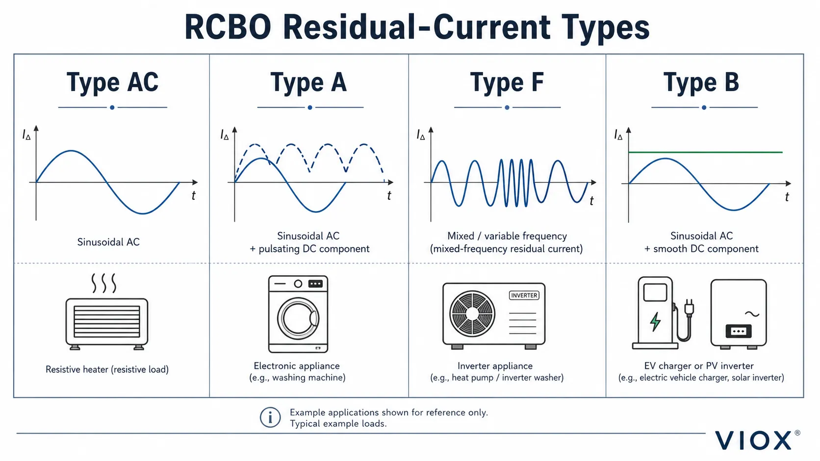
- Type matters as much as current rating. Type AC, A, F, and B RCBOs detect different residual-current waveforms.
- 30 mA is common for additional personal protection, while 100 mA and 300 mA are usually used for upstream, fire-protection, or selectivity applications depending on local rules.
- B, C, and D curves are overcurrent trip curves, not leakage-current sensitivities.
- The RCBO current rating must coordinate with the cable, not just the connected appliance.
- Breaking capacity must exceed the prospective short-circuit current at the installation point.
- EV chargers, PV inverters, VFDs, and heat pumps need careful RCD-type selection because DC or high-frequency residual currents can affect ordinary RCD operation.
RCBO Selection Checklist
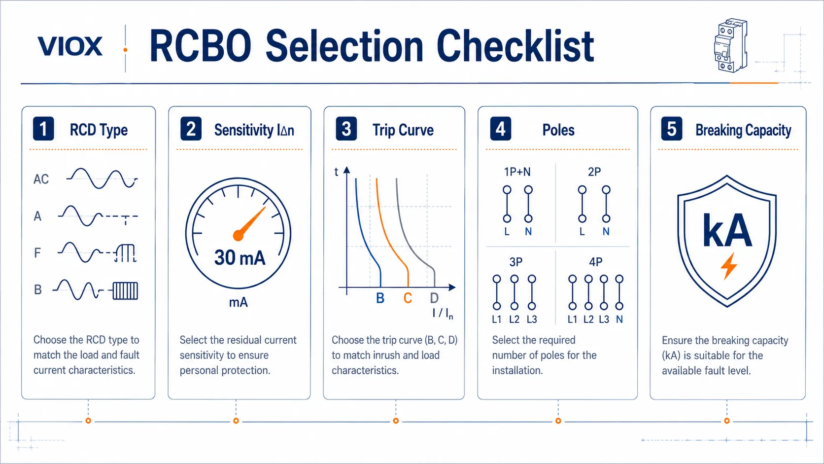
| Selection factor | What to check | Typical options | Common mistake |
|---|---|---|---|
| Residual-current type | Waveform of possible leakage current | Type AC, A, F, B | Using Type AC on circuits with electronic loads that may need Type A, F, or B |
| Sensitivity | Rated residual operating current, IΔn |
10 mA, 30 mA, 100 mA, 300 mA | Choosing 10 mA everywhere and creating nuisance trips |
| Rated current | Circuit design current and conductor ampacity | 6 A to 63 A common in final circuits | Oversizing the RCBO so the cable is not properly protected |
| Trip curve | Load inrush current | B, C, D | Using B curve on high-inrush equipment or D curve where fault current is too low |
| Poles | Conductors to be switched and monitored | 1P+N, 2P, 3P+N, 4P | Mixing neutrals between RCBO-protected circuits |
| Breaking capacity | Prospective short-circuit current at the board | 6 kA, 10 kA, 16 kA and higher | Treating 6 kA or 10 kA as a universal rating |
| Standard and marking | Product standard and application scope | IEC/EN 61009-1, IEC 62423 where applicable | Assuming every RCBO is suitable for every installation environment |
Step 1: Define the Circuit Before Choosing the RCBO
Before selecting a model, identify the actual circuit duty:
- supply system: single-phase, three-phase, with or without neutral
- load type: lighting, sockets, heating, pump, motor, EV charger, PV inverter, heat pump, VFD, or mixed loads
- design current of the circuit
- conductor size, installation method, ambient temperature, and derating factors
- available short-circuit current at the distribution board
- expected leakage current from filters, long cables, electronics, or multiple connected appliances
- whether the circuit is safety-critical or should remain independent from other circuits
This is where RCBOs often outperform a shared RCCB plus multiple MCBs. With individual RCBOs, one leakage fault normally disconnects only one circuit instead of taking out a whole group. For the architecture comparison, see VIOX’s guide to RCBO vs RCCB and MCB.
Step 2: Choose the Correct RCBO Type
The RCBO type describes the residual-current waveform the device is designed to detect. This is separate from the B/C/D overcurrent curve.
| RCBO type | Residual current detected | Typical use | Selection caution |
|---|---|---|---|
| Type AC | Sinusoidal AC residual current | Simple resistive AC circuits where permitted | Not suitable for many modern electronic loads |
| Type A | Sinusoidal AC and pulsating DC residual current | General circuits with electronic appliances, rectifiers, LED drivers, washing machines, induction loads | Often a practical minimum for modern final circuits, but still not enough for smooth DC residual current |
| Type F | Type A behavior plus selected mixed-frequency residual currents and improved behavior with some single-phase inverter loads | Heat pumps, washing machines, single-phase variable-speed drives where specified | Verify equipment manufacturer instructions |
| Type B | AC, pulsating DC, high-frequency components, and smooth DC residual current | EV charging, PV inverters, VFDs, medical or industrial equipment where smooth DC leakage can occur | Higher cost and more specialized; choose when the application actually requires it |
Type AC RCBO
Type AC RCBOs detect sinusoidal AC residual current. They may still appear in older installations or simple circuits, but they are increasingly limited in modern applications because many loads contain rectifiers, electronic power supplies, filters, and inverter stages.
Do not specify Type AC just because it is the cheapest option. Confirm that the connected load and local wiring rules allow it.
Type A RCBO
Type A RCBOs detect sinusoidal AC residual current and pulsating DC residual current. They are commonly used for many modern single-phase final circuits because household, commercial, and light industrial loads often include electronic components.
Type A is usually a safer default than Type AC for general modern circuits, but it is not a universal solution. If smooth DC residual current or high-frequency leakage may occur, Type F or Type B may be required.
Type F RCBO
Type F RCBOs are used where the load can produce residual-current components beyond normal Type A behavior, especially some single-phase inverter-driven equipment. Examples can include selected heat pumps, washing machines, air-conditioning equipment, and variable-speed appliances.
Use Type F when the equipment manufacturer, project specification, or local rules require it. Do not assume that every motor or appliance circuit automatically needs Type F.
Type B RCBO
Type B RCBOs detect a broader range of residual currents, including smooth DC components. They are often considered for equipment such as EV chargers, PV inverters, frequency converters, and certain industrial or medical systems.
The key is not the product category alone. The real question is whether the equipment can generate residual current that would blind or saturate a Type AC or Type A device. For EV charging, the correct solution may be Type B, Type A with 6 mA DC residual current detection, Type A-EV, or a charger-integrated residual direct current detecting device depending on the equipment and local rules. For a deeper EV-specific treatment, see EV charger RCD selection: Type B vs Type F vs Type EV.
Step 3: Choose RCBO Sensitivity
RCBO sensitivity is the rated residual operating current, usually written as IΔn. It defines the residual current level at which the leakage-protection function is intended to trip.
| Sensitivity | Typical role | Common application | Important caution |
|---|---|---|---|
| 10 mA | Higher sensitivity protection | Special circuits, wet areas, medical-adjacent or local high-risk equipment where specified | More prone to nuisance tripping from normal leakage |
| 30 mA | Additional personal protection | Final circuits, sockets, outdoor circuits, many residential and commercial circuits | Must still account for accumulated leakage |
| 100 mA | Upstream or equipment protection | Distribution circuits, selective layouts, some special loads | Not normally a replacement for 30 mA final-circuit personal protection |
| 300 mA | Fire-risk and upstream protection | Main or sub-distribution protection, TT-system strategies, fire protection where specified | Requires coordination with downstream devices |
For final circuits where personal shock protection is required, 30 mA is widely used in IEC-based installations. However, the final choice must follow local regulations, earthing system, circuit purpose, and risk assessment.
Higher values such as 100 mA and 300 mA are usually chosen for upstream protection, fire-risk reduction, or discrimination with downstream 30 mA devices. In those layouts, a time-delayed or selective upstream device may be needed so that a downstream RCBO trips first.
For a more detailed sensitivity discussion, see VIOX’s guide on how to choose the right RCCB sensitivity.
Step 4: Choose the Rated Current
The rated current of an RCBO is the current the overcurrent section is designed to carry continuously under specified conditions. It must be selected around the circuit, not only around the appliance nameplate.
For IEC-style circuit design, the basic logic is:
IB ≤ In ≤ IZWhere:
IB= design current of the loadIn= rated current of the RCBOIZ= current-carrying capacity of the conductor after installation and derating factors
This means the RCBO rating should be high enough for the intended load, but not so high that the cable is left under-protected.
Avoid fixed rules such as “2.5 mm² cable always equals 20 A” or “1.5 mm² cable always equals 16 A” without checking installation method, insulation type, grouping, ambient temperature, local code, and cable derating. Those shortcuts are the kind of thing that causes overheating problems in real panels.
Step 5: Choose the Trip Curve: B, C, or D
The trip curve belongs to the overcurrent protection side of the RCBO. It describes the instantaneous magnetic trip behavior under short-circuit or high-inrush conditions.
| Curve | Instantaneous trip range | Typical loads | Selection risk |
|---|---|---|---|
| B curve | About 3 to 5 times In |
Resistive loads, lighting, low-inrush final circuits | May nuisance trip on motors, transformers, or large capacitive loads |
| C curve | About 5 to 10 times In |
General sockets, small motors, commercial panels, moderate inrush | Must still trip fast enough under fault conditions |
| D curve | About 10 to 20 times In |
Transformers, high-inrush motors, industrial loads | Requires careful fault-current and loop-impedance verification |
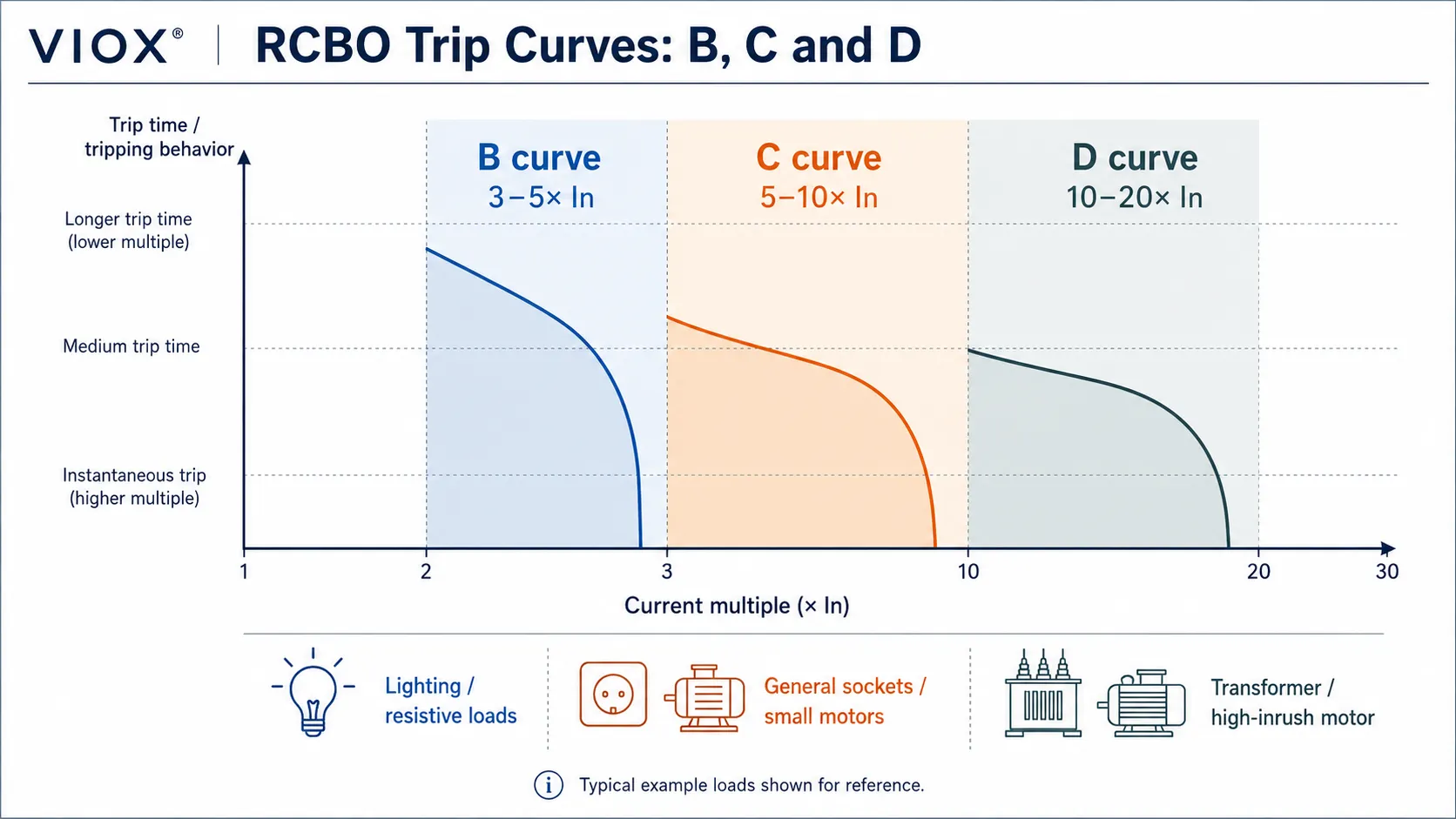
Choose the curve by the load’s inrush behavior and the circuit’s available fault current. A D-curve RCBO may solve nuisance tripping during startup, but it can also delay fault clearing if the circuit impedance is high and the short-circuit current is too low.
For a deeper explanation, see VIOX’s article on understanding trip curves.
Step 6: Choose Pole Configuration and Neutral Arrangement
Every live conductor that belongs to the protected circuit must pass through the RCBO’s residual-current sensing system. Incorrect neutral routing is one of the most common causes of unwanted tripping.
| Configuration | Typical use | What to verify |
|---|---|---|
| 1P+N RCBO | Single-phase final circuits | Whether neutral is switched or solid neutral, and whether the line pole has overcurrent protection |
| 2P RCBO | Single-phase circuits needing both line and neutral disconnection | Whether both poles are switched and how overcurrent protection is applied |
| 3P RCBO | Three-phase circuits without neutral | All three phase conductors pass through the device |
| 3P+N or 4P RCBO | Three-phase circuits with neutral | Neutral must pass through the residual-current sensor and follow manufacturer wiring |
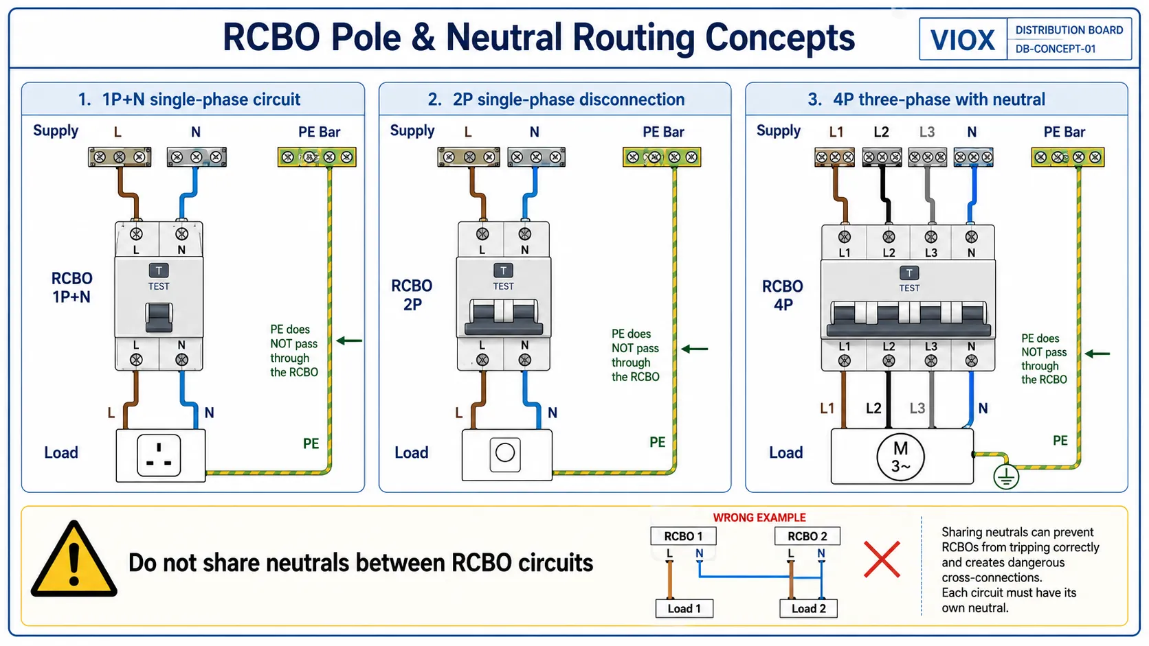
Manufacturer terminology can vary. 1P+N may mean a protected line pole with a switched neutral, a solid neutral path, or another arrangement depending on the design. Always verify the wiring diagram, terminal marking, neutral treatment, and product datasheet.
Neutral Routing Rule
Do not share neutrals between downstream RCBO circuits. If the line conductor of one circuit returns through the neutral of another circuit, the RCBO sees a current imbalance and trips. In worse cases, mixed neutrals can create misleading test results and unsafe maintenance assumptions.
Step 7: Check Breaking Capacity
Breaking capacity is the maximum short-circuit current the RCBO can interrupt under its rated test conditions. It is usually marked in kA, such as 6 kA, 10 kA, or 16 kA.
The rule is direct:
RCBO breaking capacity ≥ prospective short-circuit current at the installation pointThe prospective short-circuit current near the service entrance or transformer can be much higher than at the end of a long final circuit. That is why a 6 kA RCBO may be acceptable in one board and insufficient in another.
When comparing RCBOs, check:
- rated short-circuit capacity marking
- rated voltage condition for that value
- applicable product standard
- upstream backup protection or coordination requirements
- whether the installed location has a calculated or measured fault level
For a focused treatment, use VIOX’s RCBO breaking capacity guide for 6 kA, 10 kA, and 16 kA selection.
Step 8: Check Standards and Product Markings
For IEC-based markets, RCBOs for household and similar applications are commonly associated with IEC/EN 61009-1, which covers residual-current operated circuit-breakers with integral overcurrent protection. Type F and Type B residual-current devices are also associated with IEC 62423 where applicable.
Do not select by catalog title alone. Check the actual product marking and datasheet for:
- standard reference
- rated voltage and frequency
- rated current
- residual-current type
- rated residual operating current
- trip curve
- breaking capacity
- pole configuration
- terminal wiring diagram
- operating temperature and installation limitations
- line/load direction if specified
If a project requires a specific national certification, do not assume that IEC-style markings are enough. Verify the approval required by the market and project specification.
RCBO Selection by Application
| Application | Common starting point | What to check before final selection |
|---|---|---|
| Lighting circuit | Type A, 30 mA, B curve or C curve depending inrush | LED driver leakage and inrush, local code, circuit grouping |
| General socket circuit | Type A, 30 mA, B or C curve | Expected connected equipment, leakage accumulation, cable rating |
| Kitchen or appliance circuit | Type A or Type F, 30 mA | Electronic controls, heating elements, compressor or motor inrush |
| Bathroom or wet-location circuit | 30 mA, sometimes 10 mA where specified | Local wiring rules, nuisance trip risk, equipment leakage |
| Outdoor circuit | Type A, 30 mA common | Moisture exposure, long cables, portable tools, enclosure protection |
| Heat pump or inverter appliance | Type F or Type B where specified | Manufacturer requirement, leakage waveform, starting behavior |
| EV charging circuit | Type B, Type A-EV, or Type A with 6 mA DC detection depending design | Charger standard, internal RDC-DD, local regulation, upstream RCD coordination |
| Solar PV inverter AC side | Type A or Type B depending inverter design and instructions | Inverter residual-current detection, transformerless topology, local code |
| Upstream distribution circuit | 100 mA or 300 mA, often selective/time-delayed where needed | Fire protection, discrimination, downstream 30 mA RCBOs |
This table is a starting point, not a substitute for the equipment manufacturer’s installation manual or the local wiring code.
Common RCBO Selection Mistakes
Mistake 1: Choosing by Amperage Only
An RCBO marked 32 A is not automatically suitable for every 32 A circuit. The residual-current type, curve, breaking capacity, voltage rating, and conductor protection must all match the installation.
Mistake 2: Treating Type AC as Universal
Many modern loads include rectifiers, filters, and switching power supplies. If these loads can produce pulsating DC or other non-sinusoidal residual currents, Type AC may not be appropriate.
Mistake 3: Using Type B Everywhere
Type B is technically broader, but it is not automatically the best economic or engineering choice for every circuit. Use it where the leakage-current waveform requires it, such as certain EV, PV, VFD, or industrial applications.
Mistake 4: Ignoring Normal Leakage Current
Electronic equipment, long cable runs, surge protective devices, and filters can all contribute normal leakage current. If several loads are grouped on one device, accumulated leakage may cause nuisance tripping even when no dangerous fault exists.
For the distinction between leakage current and residual current, see VIOX’s guide to leakage current vs residual current vs ground current.
Mistake 5: Oversizing the RCBO Relative to the Cable
Oversizing may prevent nuisance trips, but it can also fail to protect conductors against overload. Use the circuit design current and corrected cable ampacity as the basis.
Mistake 6: Choosing a D Curve Without Fault-Current Verification
D curve devices tolerate high inrush current, but they require sufficient fault current for reliable magnetic tripping. If the fault loop impedance is too high, a D curve may not clear faults as expected.
Mistake 7: Mixing Neutrals
Each RCBO circuit must keep its line and neutral paths together. Shared neutrals, borrowed neutrals, or neutral bars that do not match the protection layout are classic causes of RCBO tripping during commissioning.
RCBO vs RCCB Plus MCB
Both approaches can be correct.
| Layout | Strength | Limitation |
|---|---|---|
| RCCB + multiple MCBs | Lower device count and familiar board layouts | One leakage fault may disconnect several circuits |
| RCBO per circuit | Better circuit selectivity and easier fault isolation | Higher device count and more neutral-routing discipline |
Choose RCBOs when the design needs better continuity, individual circuit protection, easier troubleshooting, or compact combined protection. Choose RCCB plus MCB where the project specification, cost structure, or board architecture supports grouped residual-current protection.
Final RCBO Specification Checklist
Before placing an order, confirm these details:
- RCBO type: AC, A, F, B, or special EV/PV requirement
- sensitivity: 10 mA, 30 mA, 100 mA, 300 mA, or project-specific value
- rated current: coordinated with load and conductor ampacity
- trip curve: B, C, or D
- breaking capacity: equal to or above the prospective short-circuit current
- poles: 1P+N, 2P, 3P, 3P+N, or 4P as required
- neutral arrangement: switched neutral, solid neutral, or manufacturer-specific design
- rated voltage and frequency
- standard and certification requirement
- terminal compatibility with the distribution board busbar system
- line/load direction and wiring diagram
- leakage accumulation and upstream/downstream selectivity
For product evaluation and model selection, compare the installation data with the actual RCBO datasheet: system voltage, circuit current, cable rating, fault level, load type, and local code requirement. If you are building a distribution board or sourcing for OEM projects, review the VIOX RCBO product range against the selection checklist above.
FAQ
What is the best RCBO type for modern circuits?
For many modern final circuits, Type A is often a more practical starting point than Type AC because it can detect pulsating DC residual current as well as sinusoidal AC residual current. However, Type F or Type B may be needed for inverter-driven equipment, EV chargers, PV inverters, or other loads that can produce different residual-current waveforms.
Is Type A RCBO better than Type AC?
Type A detects more residual-current waveforms than Type AC, so it is usually better suited to circuits with electronic loads. That does not mean every circuit automatically needs Type A, but Type AC should not be used where the load or local rule requires Type A, F, or B.
Should I choose 10 mA or 30 mA RCBO?
30 mA is widely used for additional personal protection on final circuits. 10 mA gives higher sensitivity but is more prone to nuisance tripping, so it is usually reserved for special high-risk or local-protection applications where the design allows it.
What is the difference between 30 mA and 300 mA RCBO?
30 mA RCBOs are commonly used for personal shock protection on final circuits. 300 mA devices are generally used for upstream, fire-protection, or selective protection strategies and should not be treated as a direct substitute for 30 mA final-circuit protection where 30 mA is required.
Should I use B curve or C curve RCBO?
Use B curve for low-inrush circuits such as many lighting or resistive loads. Use C curve for circuits with moderate inrush, such as general socket circuits or small motors. The final choice must still satisfy fault-clearing requirements.
When is a D curve RCBO used?
D curve RCBOs are used for high-inrush loads such as transformers or larger motors. They should be specified only after checking that the available fault current is high enough to trip the device correctly under short-circuit conditions.
What breaking capacity should an RCBO have?
The RCBO breaking capacity must be equal to or greater than the prospective short-circuit current at the installation point. Common values include 6 kA, 10 kA, and 16 kA, but the correct choice depends on the actual fault level.
Can I replace an MCB with an RCBO?
Often yes, if the RCBO matches the circuit current rating, curve, breaking capacity, voltage, pole configuration, busbar system, and residual-current protection requirement. It is not a simple like-for-like replacement unless all ratings and wiring details match.
Why does an RCBO trip with no obvious fault?
Common causes include accumulated leakage current, moisture, insulation degradation, mixed neutrals, shared neutrals, faulty appliances, VFD or filter leakage, surge protective device leakage, or an incorrect RCD type for the load.
Does an RCBO protect against electric shock?
An RCBO can provide residual-current protection that reduces electric shock risk when current leaks to earth or another unintended path. It cannot remove every shock hazard, such as a person touching line and neutral at the same time where the current remains balanced.
Sources and Technical References
- Existing VIOX page reviewed: How to Select the Right RCBO
- General RCD and RCBO principles: Residual-current device
- IEC/EN 61009-1: residual-current operated circuit-breakers with integral overcurrent protection for household and similar uses
- IEC 60755: general residual-current operated protective-device requirements and RCD type framework
- IEC 62423: Type F and Type B residual-current devices where applicable
