On this page
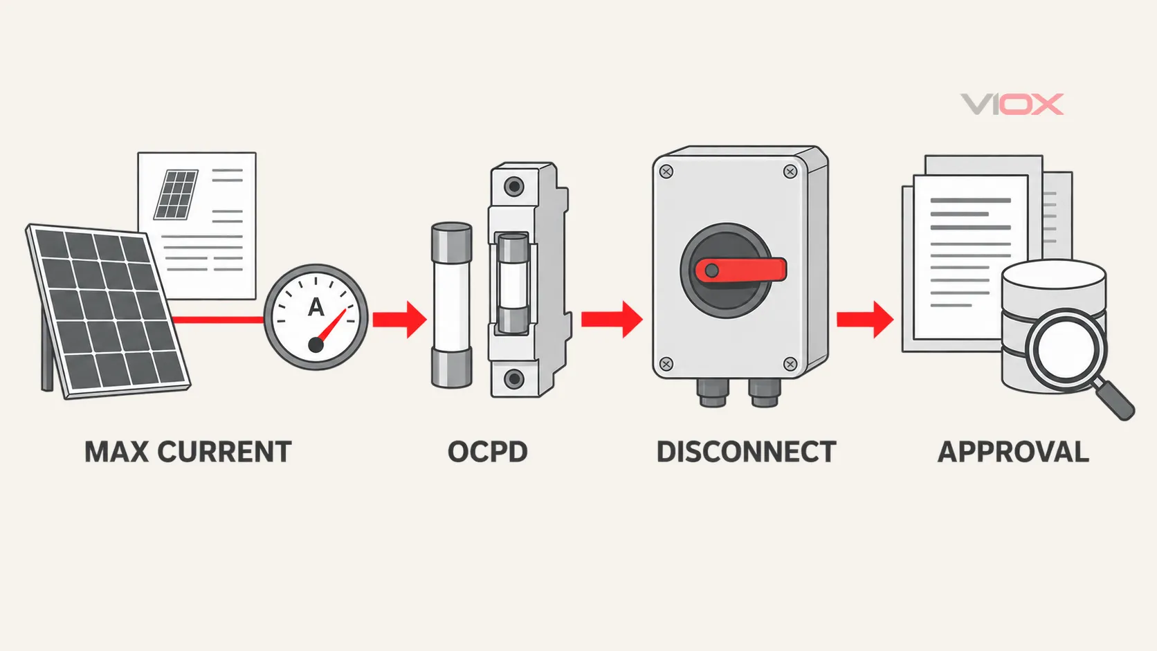
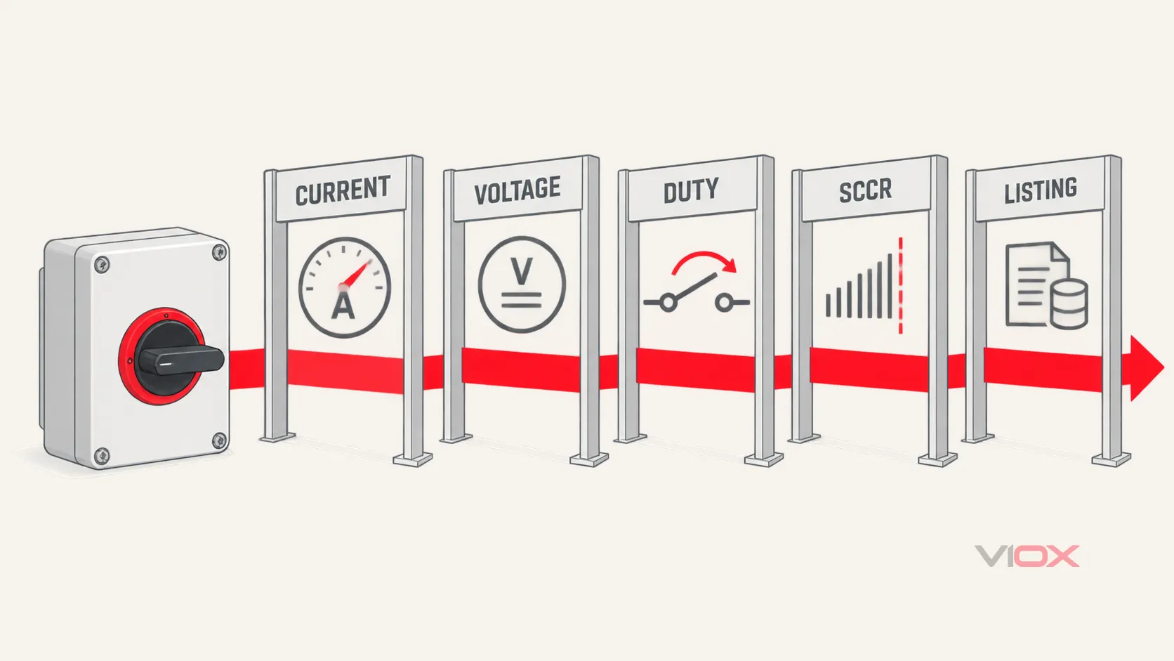
PV disconnect sizing is not a universal Isc × 1.56 calculation. The defensible method is to keep four decisions separate:
- Calculate the maximum circuit current under the locally adopted NEC edition.
- Decide whether overcurrent protection is required, then size the OCPD if it is.
- Select the DC disconnect for maximum circuit current, maximum voltage, required switching function, and environmental conditions.
- Verify the complete product and assembly evidence: listing, markings, SCCR, pole arrangement, enclosure, conductor terminals, and manufacturer instructions.
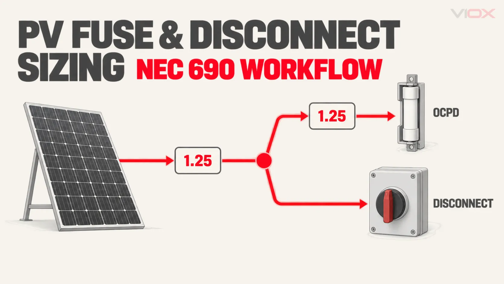
The familiar 156% value comes from two 125% steps in one common NEC pathway: first from module short-circuit current to maximum circuit current, then from maximum circuit current to a conventional OCPD rating. The second factor is not automatically a disconnect-rating factor.
Design boundary: NEC editions and local amendments are adopted on different schedules. Use the edition enforced by the authority having jurisdiction (AHJ), the module and inverter instructions, the listed-equipment conditions, and the project engineering record. This article explains the decision structure; it is not a stamped design.
The Four-Lane Sizing Model
| Lane | Question | Main output | Do not confuse it with |
|---|---|---|---|
| Circuit current | What is the NEC maximum current for this source, output, or input circuit? | Maximum circuit current | Fuse size or switch catalog ampere value |
| Conductors and OCPD | Is overcurrent protection required, and what rating can the complete circuit accept? | Conductor ampacity and OCPD rating/placement | Disconnect carrying current |
| Disconnect | What current, voltage, switching duty, poles, enclosure, and terminals are required? | Disconnect specification | A fuse or circuit breaker trip function |
| Approval and fault duty | Is the exact device or assembly suitable for the market and available fault current? | Listing, SCCR/interrupting evidence, markings, documents | A standards logo or family-level brochure |
Inputs Required Before You Calculate
Do not start with a switch catalog. Collect the circuit data first.
| Input | Why it matters | Evidence source |
|---|---|---|
| Module Isc and Voc | Starting values for current and voltage calculations | Exact module datasheet/nameplate |
| Maximum series fuse rating | Upper constraint on source-circuit OCPD | Module datasheet/nameplate |
| Modules in series per string | Establishes string open-circuit voltage | Array design |
| Parallel strings at the point being sized | Establishes combined current and reverse-current exposure | Single-line diagram |
| Lowest expected temperature | Used for maximum PV voltage | Site design basis and NEC method |
| Inverter or DC-to-DC converter limits | May affect permitted calculation method, backfeed, and equipment compatibility | Exact product instructions |
| Conductor type, temperature rating, and installation | Needed for ampacity, correction, and adjustment | Wiring method and conductor data |
| Other connected sources | Grid, battery, or parallel sources can change available current and OCPD placement | Complete system architecture |
| Available fault current | Needed for interrupting and short-circuit ratings | Engineering study or validated calculation |
| Disconnect function | Load-breaking, equipment isolation, maintenance isolation, or another defined function | Design narrative and adopted code |
| Ambient, enclosure, altitude, and mounting | Can change usable current and environmental suitability | Site conditions and product instructions |
| Target market and AHJ | Determines adopted code and required listing/evidence | Project requirements |
If the open question is where the disconnect belongs rather than how it is rated, start with the solar disconnect location guide.
Step 1: Calculate Maximum PV Circuit Current
For a conventional PV source circuit using the module short-circuit-current method, the familiar starting point is:
Maximum source-circuit current = module Isc × 1.25
For identical strings combined in parallel:
Maximum combined output current = number of parallel strings × module Isc × 1.25
The 1.25 factor here converts the module Isc basis into maximum circuit current for this common NEC method. It is not yet the fuse size, conductor ampacity, or disconnect catalog size.
Article 690 also contains pathways for circuits connected to electronic power converters and for certain engineered large-scale PV calculations. Bifacial-module current treatment and equipment-specific limits can also change the input. Therefore, use the method permitted by the adopted NEC edition and supported by the project documents instead of forcing every system into the same equation.
Conventional example: six parallel strings
Assume six identical strings, each using modules with:
- Isc = 14.45 A
- maximum series fuse rating = 25 A
- no additional current contribution included in this simplified example
The combined maximum circuit current is:
6 × 14.45 A × 1.25 = 108.4 A108.4 A is the maximum circuit current at the combined output for this calculation. It is not automatically a 150 A disconnect requirement.
Step 2: Decide Whether an OCPD Is Required
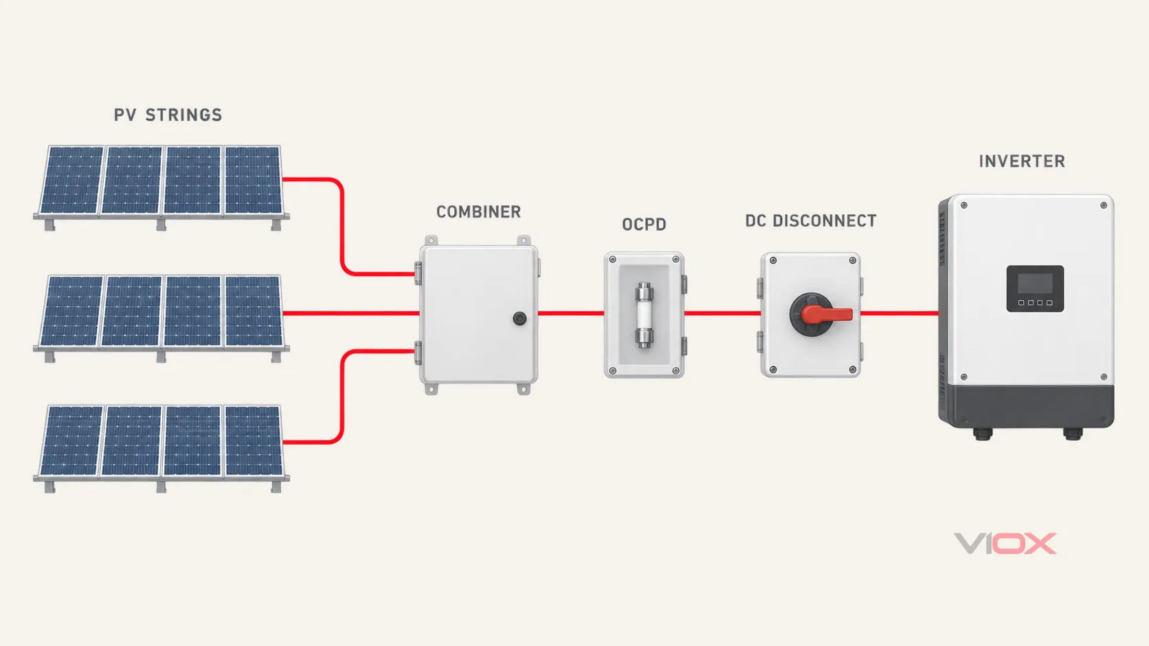
A PV circuit does not require a fuse merely because it contains a module. PV sources are current-limited, and some circuits can omit an OCPD when the applicable NEC conditions are satisfied—for example, when the conductor has sufficient ampacity and current from all sources cannot exceed the equipment’s permitted overcurrent limit.
Overcurrent protection becomes important when parallel strings, batteries, the utility, or another source can drive damaging current into a circuit or conductor. OCPD location must address the direction and source of that current, not simply be placed where it is convenient.
Ask these questions in order:
- What sources can feed the conductor during a fault?
- Does conductor ampacity cover the maximum current from those sources after all required corrections and adjustments?
- Can current from all sources exceed the module, converter, conductor, or equipment limit?
- Does the adopted NEC edition permit protection at one end, require protection at both ends, or permit no OCPD for this circuit?
- Do the module, inverter, combiner, fuse holder, or other listed-equipment instructions impose an additional condition?
For a deeper treatment of the no-fuse conditions and parallel-string reverse current, see when NEC 690.9 requires PV string fuses.
Step 3: Size the PV Fuse or Other OCPD
Where an OCPD is required, a common NEC pathway sets its minimum rating at 125% of maximum circuit current unless a permitted 100%-rated assembly pathway applies.
Conventional OCPD minimum = maximum circuit current × 1.25
Combining that with the conventional module-Isc method produces:
Isc × 1.25 × 1.25 = Isc × 1.5625This is the origin of the shorthand “156% rule.” It can be useful for a conventional source-circuit OCPD calculation, but only after confirming that the adopted code path applies.
The selected fuse or breaker must satisfy every applicable constraint—not only the calculated minimum:
- at or above the required minimum rating;
- at or below the module’s maximum series fuse rating where that limit applies;
- compatible with the conductor ampacity after correction and adjustment;
- suitable for the maximum DC voltage;
- adequate interrupting rating for the available fault current;
- correct PV application category, listing, holder, and assembly combination; and
- permitted by the equipment instructions and standard ampere-size rules.
If the next standard OCPD size exceeds the module, conductor, holder, or equipment limit, do not “round up and hope.” Change the conductor, architecture, string grouping, or equipment so that all constraints can be satisfied.
For North American product evaluation, UL Solutions identifies UL 248-19 and UL 2579 routes for PV fuses. In IEC-oriented projects, IEC 60269-6 provides supplementary requirements for fuse-links protecting PV strings and arrays up to 1,500 V DC. A gPV marking or IEC test report does not by itself satisfy a U.S. listing requirement.
Step 4: Size the DC Disconnect Current—Separately
For equipment isolation under NEC Article 690, the disconnecting means or isolating device must be evaluated for the circuit it controls. As a baseline, the disconnect’s applicable current rating must not be less than the circuit’s maximum current. Then apply the exact product’s listing conditions, continuous-use restrictions, ambient corrections, enclosure effects, terminal limits, and manufacturer instructions.
For the six-string example:
- maximum circuit current = 108.4 A;
- conventional OCPD minimum, if one is required on that output =
108.4 A × 1.25 = 135.5 Abefore standard-size and equipment constraints; - disconnect current basis = at least 108.4 A, followed by product-specific usage and derating checks.
The result may still be a 125 A, 150 A, 160 A, or larger catalog device depending on how the exact product is rated and used. The point is that 150 A does not follow automatically from applying the OCPD factor to the disconnect.
Do not assume a catalog current rating means the same thing across products. Verify whether it is a continuous-current rating, a general-use switch rating, a PV-specific rating, a utilization-category rating, or a rating dependent on a stated pole arrangement. The DC isolator rating guide explains those nameplate distinctions.
Step 5: Calculate Maximum DC Voltage
Current sizing alone cannot qualify a PV disconnect. Series-connected modules raise voltage, and module Voc increases as cell temperature falls.
For a string using the NEC table method, the conceptual calculation is:
Maximum PV voltage = modules in series × module Voc × applicable low-temperature correction factor
Other permitted methods can use manufacturer-provided temperature coefficients or engineered calculations. Use the method allowed by the adopted NEC edition and the site’s lowest expected temperature.
Select the fuse, holder, breaker, disconnect, combiner, SPD, and inverter input for a DC voltage at least equal to the calculated maximum. Verify any polarity, grounding, and pole-series arrangement limits. Never infer a 1,000 V or 1,500 V capability by adding markings from individual poles unless the exact instructions explicitly permit that arrangement.
Step 6: Define the Required Switching Function
“Disconnect,” “isolator,” and “switch-disconnector” are not interchangeable labels in every standard or installation.
If the device is expected to open while current is flowing, it must be evaluated and marked for the required DC load-breaking duty at the actual voltage, current, and connection arrangement. Some isolating devices are permitted only when load interruption is prevented by an interlock or when the device is marked against operation under load. A handle and an OFF symbol do not prove load-break capability.
Define the function before selecting the product:
- Will it be routinely operated under load?
- Is it only an equipment-isolation point after another device opens the circuit?
- Does the design require visible-open or lockable isolation?
- Must it serve as a PV system disconnecting means, an equipment disconnect, or only a maintenance isolator?
- What remains energized after operation?
A DC disconnect is also not automatically a rapid-shutdown system. Location and function are covered separately in the solar disconnect selection guide.
Step 7: Verify SCCR and Interrupting Ratings
Two ratings are commonly mixed up:
- Interrupting rating applies to an OCPD’s ability to interrupt fault current safely.
- Short-circuit current rating (SCCR) applies to equipment or an assembly’s ability to withstand the prospective fault current under stated conditions.
The fuse interrupting rating does not automatically become the SCCR of a combiner box or disconnect assembly. The complete assembly’s SCCR depends on the evaluated combination of disconnect, fuse and holder, terminals, busbars, enclosure, conductor range, spacing, and any current-limiting protection.
PV arrays are current-limited, but batteries, parallel combiners, and inverter or utility backfeed paths can materially change available fault current. Document every source. Verify that:
- OCPD interrupting rating is not less than available fault current at its terminals;
- disconnect and equipment SCCR are adequate for the installation;
- any series-rating or current-limiting claim is specifically permitted and documented; and
- the assembly label reflects the approved configuration.
For more detail, see PV fuse breaking capacity.
Step 8: Match the Product-Evaluation Path
Standards identify product categories; they do not approve an installation by title alone.
| Component or function | North American evaluation references identified by UL Solutions | IEC-oriented reference | What to verify |
|---|---|---|---|
| PV fuse | UL 248-19 / UL 2579 | IEC 60269-6 | Voltage, current, application, interrupting rating, holder combination |
| PV disconnect | UL 98B / UL 508I | IEC 60947-3 | Exact listing/category, current, voltage, duty, poles, markings, SCCR |
| PV circuit breaker | UL 489B | Market-specific breaker standard | Voltage, current, trip, polarity, interrupting rating, application |
| Combiner box | UL 1741 or applicable evaluated assembly path | Applicable assembly/product standards | Assembly SCCR, enclosure, terminals, protection, markings |
UL Solutions’ solar balance-of-system certification page lists these product routes. They are not interchangeable. For example, an IEC 60947-3 report can be relevant evidence for an IEC-market switch-disconnector but does not establish a UL 98B or UL 508I listing.
Before specifying a product, obtain the exact model number and verify it in the relevant certification database. A family brochure, “designed to meet,” CE marking, or a certificate for a neighboring model is not a substitute for the required listing and conditions of acceptability.
Worked Example A: One PV String
Assume one string with:
- module Isc = 14.45 A;
- module Voc = 49.5 V;
- 20 modules in series;
- maximum series fuse rating = 25 A; and
- an illustrative low-temperature voltage factor of 1.14 selected from the project’s permitted method.
Current
Maximum circuit current:
14.45 A × 1.25 = 18.06 AIf the adopted NEC conditions show that no source can drive excessive current into the string and the conductor/equipment limits are satisfied, a source-circuit OCPD may not be required.
If an OCPD is required and the conventional 125% OCPD pathway applies:
18.06 A × 1.25 = 22.58 AThe next suitable standard size may be 25 A, but only because it also respects the 25 A maximum series fuse limit, conductor ampacity, voltage, holder, and listing requirements. This example does not authorize a 25 A fuse for a different module.
The disconnect current basis remains at least 18.06 A, subject to the exact product’s use conditions. It does not become 22.58 A merely because that value was used to size an OCPD.
Voltage
Maximum string voltage for this illustrative method:
20 × 49.5 V × 1.14 = 1,128.6 V DCA 1,000 V DC device would not be adequate for that calculated value. The next candidate may be a 1,200 V or 1,500 V product, but the exact permitted voltage, pole arrangement, duty, listing, and equipment compatibility still have to be verified.
Worked Example B: Six-String Combiner Output
Using six parallel strings with the same 14.45 A module Isc:
Maximum circuit current
6 × 14.45 A × 1.25 = 108.4 AOutput OCPD, if required
108.4 A × 1.25 = 135.5 AA designer might investigate a 150 A standard OCPD, but only after confirming conductor ampacity, combiner and inverter limits, standard-size rules, interrupting rating, and listed assembly conditions. If any constraint is lower, the architecture must change.
Disconnect
The disconnect must be suitable for at least 108.4 A maximum circuit current before product-specific conditions are applied. The designer must then check maximum voltage, load-break function, SCCR, listing, enclosure, terminals, ambient, mounting, and pole arrangement.
String fuses
Each string-fuse decision also needs the reverse-current contribution from the other parallel strings and the module’s maximum series fuse rating. Do not select all six branch fuses solely from the combined-output OCPD value. The branch and output circuits are different protection zones.
Common Sizing Errors
| Error | Why it fails | Correct action |
|---|---|---|
| Multiply Isc by 1.56 and call the result the disconnect size | The second 1.25 commonly belongs to OCPD sizing, not automatically to disconnect current | Calculate maximum circuit current, then apply the exact disconnect use conditions |
| Install a fuse on every string without checking need | Some current-limited circuits can meet NEC conditions without OCPD | Evaluate current from all sources, conductor ampacity, and equipment limits |
| Choose by amperes only | A switch can have enough current capacity but inadequate DC voltage, duty, SCCR, poles, or listing | Use a multi-gate specification |
| Add pole voltages from a generic diagram | DC voltage capability can depend on a model-specific series-contact arrangement | Follow the exact model wiring diagram and marking |
| Treat fuse interrupting rating as combiner SCCR | Component and assembly ratings are different | Verify the evaluated assembly SCCR and configuration |
| Apply a generic 80%, 90%, or 95% temperature factor | Product derating depends on exact design, enclosure, ambient, and test conditions | Use model-specific curves and installation instructions |
| Treat IEC evidence as a U.S. listing | Standards and market-approval systems have different scopes | Match documentation to the project and AHJ requirement |
| Assume OFF means every PV conductor is dead | Illuminated modules can keep array-side conductors energized | Identify isolation boundaries and follow safe-work procedures |
Design Review and RFQ Checklist
Send suppliers and reviewers a complete circuit definition, not only “Need 150 A solar disconnect.” Include:
- adopted NEC edition, jurisdiction, and required product-evaluation path;
- single-line diagram and the exact disconnect location/function;
- module make/model, Isc, Voc, maximum series fuse rating, and temperature coefficients;
- modules per string and number of parallel strings;
- calculated maximum circuit current and calculation method;
- whether OCPD is required, its proposed rating/location, and the controlling constraints;
- calculated maximum DC voltage and lowest design temperature;
- available fault current and required OCPD interrupting rating/assembly SCCR;
- load-break or isolation-only requirement;
- pole arrangement, grounding, polarity, and manufacturer wiring-diagram requirement;
- conductor material, class, size, temperature rating, and terminal requirements;
- enclosure type, IP/NEMA requirement, ambient range, altitude, mounting, and cable-entry method;
- exact model datasheet, instructions, dimensional drawing, and connection diagram;
- exact listing/certificate number and database record where required; and
- required labels, accessories, lockout provision, spare fuses, and replacement-parts policy.
VIOX offers DC isolator switch and solar combiner box product families for technical comparison. Use those pages to shortlist mechanical formats and declared ratings, then request the exact model-specific evidence required by the project. Do not infer NEC compliance or a UL listing from a product-family page.
Final Rule
The safest sizing sequence is simple to remember:
Current first. OCPD second. Disconnect third. Evidence last—but mandatory.
The 156% shortcut belongs only where both 125% steps are actually required. A compliant PV design keeps maximum circuit current, fuse rating, disconnect rating, voltage, fault duty, switching function, and product approval as separate checks that must all pass.
Sources
- NFPA 70 (National Electrical Code), current and archived editions through NFPA LiNK
- UL Solutions — Solar Balance of System Certification
- UL Solutions — Product iQ certification database
- IEC — IEC 60269-6:2010+A1:2021, PV fuse-links
- IEC — IEC 60947-3:2020+A1:2025, switches, disconnectors, switch-disconnectors and fuse-combination units