On this page
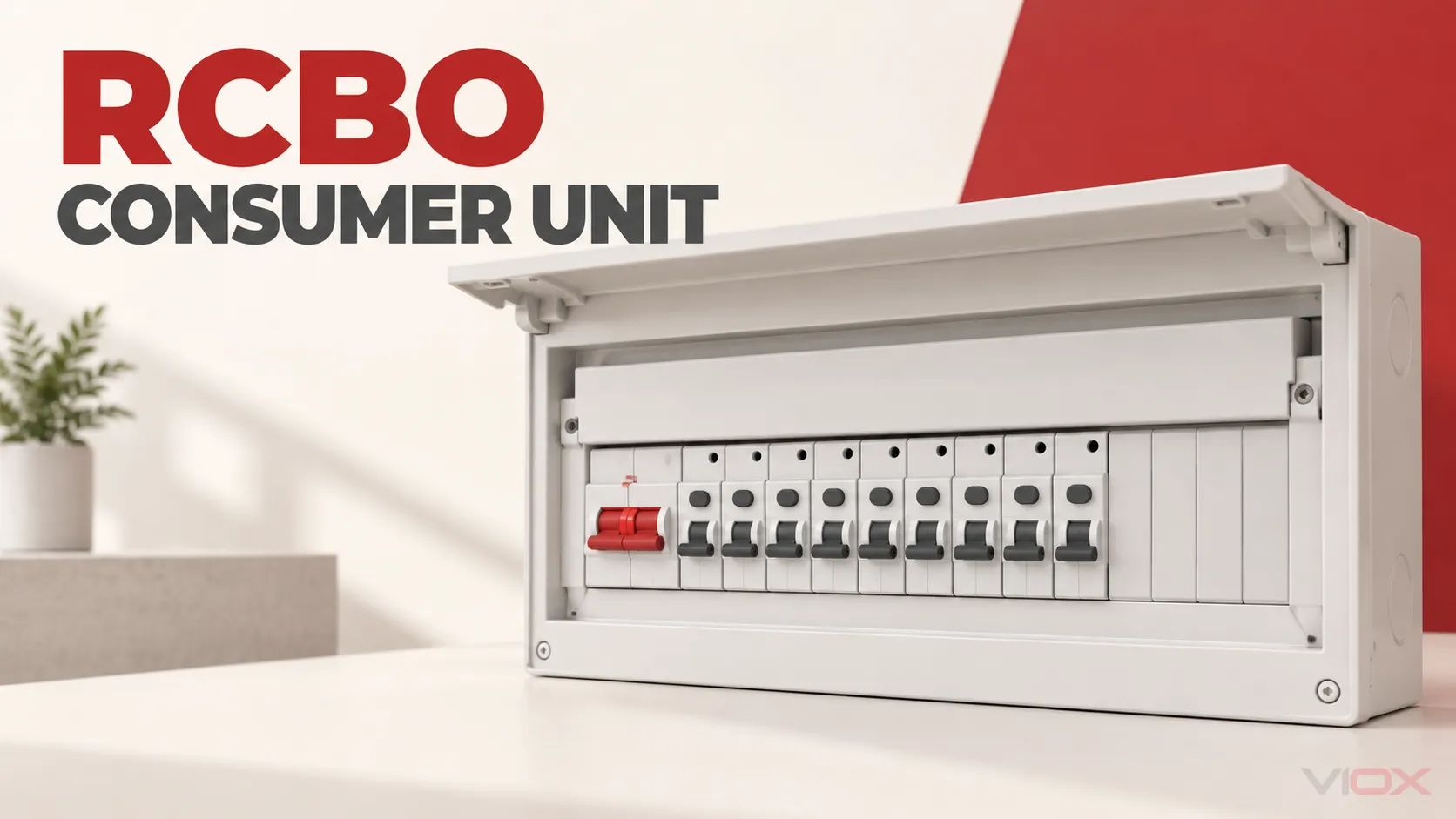
An RCBO consumer unit is a distribution board in which each outgoing circuit is protected by its own Residual Current operated Circuit-Breaker with integral Overcurrent protection (RCBO). Each RCBO combines residual-current, overload, and short-circuit protection for one circuit. As a result, a fault on one outgoing circuit will normally disconnect that circuit without relying on a shared RCD to protect several unrelated circuits.
That architecture improves circuit separation, but it does not make every RCBO board suitable for every installation. A complete specification must cover two layers:
- The consumer-unit assembly: enclosure, incomer, busbar, terminals, number of ways, fault rating, thermal limits, optional Surge Protective Device (SPD), documentation, and market approval.
- Each outgoing RCBO: rated current, trip curve, residual-current sensitivity and type, poles, breaking capacity, voltage, directionality, and circuit compatibility.
If either layer is incomplete, the board is not ready for approval or purchase.
Safety boundary: Consumer-unit design, replacement, connection, inspection, and testing must be completed by competent persons under the rules applicable at the installation location. This article supports specification and procurement; it is not a DIY wiring guide.
What Is Inside an RCBO Consumer Unit?
The exact arrangement varies, but an RCBO consumer unit commonly contains:
- an enclosure and internal mounting system;
- a main switch or another specified incomer;
- a busbar or manufacturer-defined distribution system;
- one RCBO for each outgoing circuit included in the design;
- neutral and protective-conductor termination facilities;
- blanking pieces and circuit identification;
- an SPD when the project requires one; and
- AFDDs, control devices, metering, or other functions when the project and assembly support them.
The term full RCBO consumer unit usually means that the outgoing final circuits use individual RCBOs rather than groups of MCBs protected by shared RCCBs. It does not prove that every way is populated, that every RCBO has the same rating, or that SPD and Arc Fault Detection Device (AFDD) functions are included. Read the circuit schedule and assembly documentation rather than relying on the marketing name.
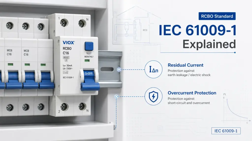
IEC 61439-3:2024 addresses distribution boards intended to be operated by ordinary persons within its stated scope. It lists outgoing protective-device families that can be incorporated in such assemblies, including devices from the IEC 61009 series. IEC 61009-1:2024 separately covers RCBO product requirements within its published AC voltage, frequency, current, and short-circuit-capacity limits. A compliant component does not, by itself, verify the complete board assembly.
RCBO Consumer Unit vs Dual-RCD Consumer Unit
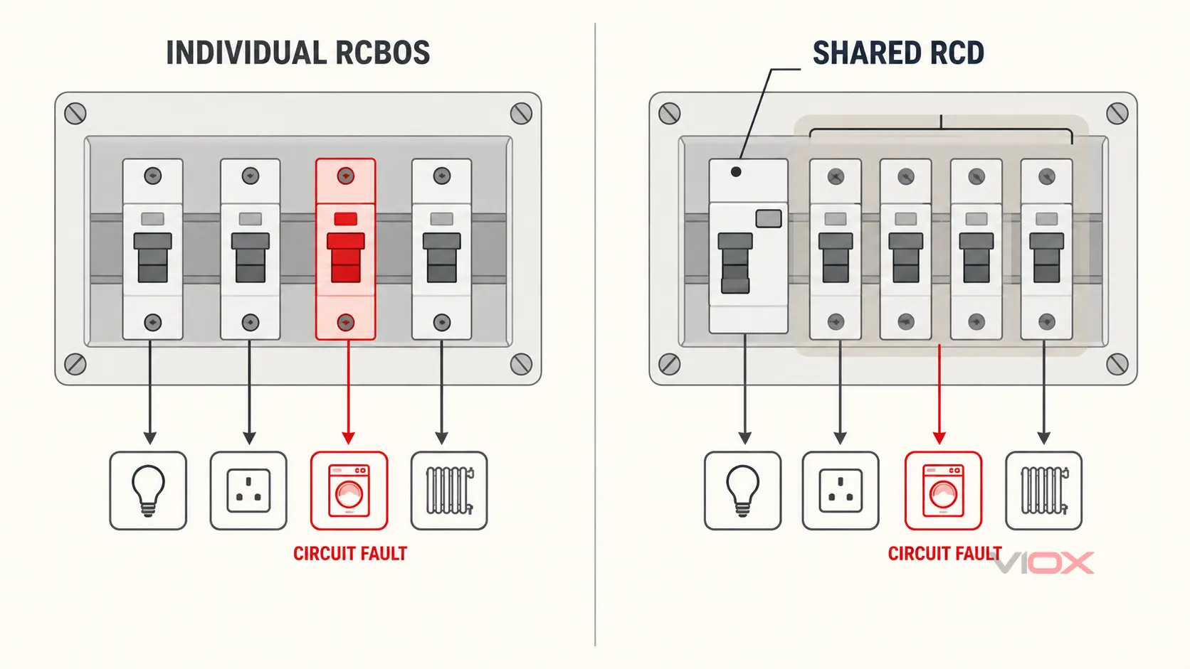
The practical difference is where residual-current protection is assigned.
| Design point | RCBO consumer unit | Dual-RCD split-load consumer unit |
|---|---|---|
| Residual-current protection | Individual RCBO for each protected outgoing circuit | One RCCB protects a group of MCB circuits |
| Overcurrent protection | Integrated in each RCBO | Individual MCB for each circuit |
| Typical residual-fault effect | Normally the affected circuit is disconnected | The shared RCD can disconnect the whole circuit group |
| Leakage accumulation | Evaluated mainly at each RCBO circuit, plus any upstream device | Normal leakage from all circuits in a group contributes at the shared RCD |
| Fault identification | The operated RCBO directly identifies the affected circuit | Further isolation within the RCD group may be needed |
| Device schedule | More RCBO order codes and circuit-specific parameters | RCCB group parameters plus individual MCB parameters |
| Assembly verification | RCBOs, busbar, enclosure, incomer, SPD and accessories must form a documented system | RCCBs, MCBs, divided busbars, enclosure and accessories must form a documented system |
An RCBO arrangement does not guarantee that only one circuit can ever lose supply. An upstream protective device, main switch, SPD backup device, supply fault, or assembly-level event can still affect multiple circuits. Nor does a dual-RCD layout automatically fail the applicable rules. The correct architecture depends on the local installation standard, required circuit division, leakage behavior, continuity objectives, cost, available space, and verified assembly design.
For the deeper architecture decision, see RCBO vs RCCB plus MCB.
How to Choose an RCBO Consumer Unit
Start with the installation and circuit schedule, not with the number printed on the enclosure.
1. Confirm the Market and Assembly Framework
Record the destination country, installation type, applicable wiring rules, required product approvals, and responsibility for certification. “IEC” is not a universal market approval.
For an IEC-based domestic or similar distribution board, IEC 61439-3 may be relevant to the assembly and IEC 61009-1 to the RCBOs, but national adoptions and installation rules still control acceptance. In England, Approved Document P describes the building-regulation framework for electrical safety in dwellings and the routes used to demonstrate compliance.
2. Define the Incoming Supply and Incomer
Record:
- nominal voltage and frequency;
- phase and neutral arrangement;
- earthing system;
- supply polarity and isolation requirements;
- upstream protective device;
- maximum demand or design current;
- prospective fault current at the board; and
- any generation, storage, EV charging, or alternative supply that can create reverse or multiple-source power flow.
The main switch rating must suit the assembly design and calculated duty. Do not select it only by copying the service-fuse marking. Verify how maximum demand, upstream protection, thermal loading, and manufacturer limits interact.
3. Choose the Number of Ways and Expansion Margin
Count every outgoing circuit, then identify realistic future additions such as EV charging, solar photovoltaic equipment, a heat pump, an outbuilding, or storage. A spare physical module is useful only if the enclosure, busbar, terminals, thermal design, incomer, and documentation support the future device.
Keep these terms separate:
- ways: outgoing circuit positions defined by the assembly;
- modules: physical width occupied by devices; and
- spare capacity: a design allowance, not merely an empty opening.
A two-module device can consume more than one nominal module while still serving one circuit. Check the exact board and device dimensions.
4. Build the Outgoing-Circuit Schedule
Every circuit needs its own RCBO decision. At minimum, record:
| Circuit field | What determines it |
|---|---|
| Circuit name and duty | Load schedule and operational requirement |
Design current IB |
Calculated circuit load |
Corrected conductor capacity IZ |
Cable, installation method, grouping, ambient conditions, insulation, and applicable derating |
RCBO rated current In |
Coordination with IB, IZ, terminals, and applicable overload rules |
| Trip curve | Inrush magnitude and duration plus required fault-disconnection performance |
Residual-current sensitivity IΔn |
Protection purpose, local rules, leakage budget, and selectivity |
| Residual-current type | Possible residual-current waveform and equipment instructions |
| Pole and neutral arrangement | Supply, required switching, monitored conductors, and exact product design |
| Breaking capacity | Maximum prospective short-circuit current and any documented backup combination |
| Directionality | Power-flow conditions and exact manufacturer declaration |
Use the complete RCBO selection guide for the circuit-level calculation. The consumer-unit schedule should contain the result of that process, not replace it with a single standard RCBO for every circuit.
5. Check Residual-Current Type and Leakage by Circuit
Type AC, A, F, and B describe residual-current waveform capability. They are independent of B, C, and D overcurrent curves. Modern electronic loads, inverters, EV charging equipment, heat pumps, and variable-speed drives can change the required residual-current response.
Do not assign a type from the appliance category alone. Use the exact equipment instructions, converter topology, integrated residual-current monitoring, local rules, and upstream coordination. IEC 62423 adds requirements for Type F and Type B residual-current devices used with the relevant general RCD standards.
Normal leakage also needs a budget. Filters, long cables, SPDs, and connected electronic equipment can contribute standing leakage. Individual RCBOs separate the circuits, but each circuit still needs adequate margin between normal leakage and the selected operating threshold.
6. Verify Fault Capacity and the Complete Assembly
The board and every protective-device declaration used in the design must be suitable for the maximum credible fault level at the installation point. Check:
- the RCBO’s applicable short-circuit-capacity declaration;
- the assembly’s rated or conditional short-circuit capability;
- voltage and standard conditions attached to those values;
- any required upstream backup device; and
- the exact manufacturer coordination table when a combination rating is used.
Physical fit is not approval. DIN-rail dimensions do not standardize busbar position, terminal geometry, thermal behavior, accessory interfaces, or assembly verification. Use the protective devices and accessories documented for the consumer-unit system unless the manufacturer provides evidence for the alternative combination.
7. Decide Whether SPD, AFDD, or Other Functions Are Required
An RCBO does not provide every protective function. Determine separately whether the installation requires:
- an SPD for transient overvoltage protection;
- an AFDD for specified arc-fault protection;
- metering or load-control equipment;
- contactors or controls;
- dedicated protection for EV, PV, storage, heat-pump, or generator interfaces; or
- additional upstream residual-current or overcurrent coordination.
These devices consume space and can affect heat dissipation, busbar arrangement, backup protection, cable routing, and the number of usable ways. Include them before choosing the enclosure.
Pre-Populated or Configurable RCBO Board?
| Procurement route | Advantage | Main verification risk |
|---|---|---|
| Pre-populated consumer unit | Faster bill of materials and known factory package | Supplied RCBO ratings or types may not match the actual circuit schedule |
| Empty or configurable assembly | Circuit-specific device schedule and expansion planning | Buyer must verify every device, busbar, blank, terminal and accessory combination |
| Part-populated package | Common functions supplied with selected circuits customized | Package assumptions can be mistaken for a complete design |
The better route is the one that matches the documented circuit schedule and assembly system. A low purchase price is not a saving if devices must be replaced, extra ways added, or compatibility re-engineered before commissioning.
RCBO Consumer Unit Specification Worksheet
Before requesting a quotation, complete the following record.
Assembly data
- Destination country and applicable installation rules:
- Required assembly standard and approvals:
- Supply voltage, frequency, phases, neutral and earthing system:
- Upstream protective device and maximum prospective fault current:
- Maximum demand and required incomer arrangement:
- Number of outgoing circuits, spare ways and module allowance:
- Enclosure material, ingress protection, mounting and cable-entry constraints:
- SPD, AFDD, metering, control and accessory requirements:
- Ambient conditions and thermal constraints:
- Required drawings, certificates, schedules and labels:
Circuit schedule
For every outgoing way, state:
Circuit: [name and load],
IB[A], correctedIZ[A], RCBOIn[A], [B/C/D or other declared curve],IΔn[mA], residual-current Type [AC/A/F/B], [pole and neutral arrangement], breaking capacity [kA under the applicable standard and voltage], [bidirectional or supply-direction requirement], and [special coordination evidence].
Acceptance evidence
Request:
- exact catalog numbers and current datasheets;
- the assembly declaration and applicable verification documentation;
- terminal and busbar drawings;
- fault-rating and backup-protection tables;
- thermal or configuration limits relevant to the populated board;
- product and market certificates required by the project; and
- installation, inspection, test, and maintenance instructions.
If the supplier cannot map each scheduled requirement to an exact device or assembly document, the quotation is incomplete.
Installation and Commissioning Boundary
Replacing or installing a consumer unit involves work at the origin of an electrical installation. Existing circuits may contain shared neutrals, neutral-to-earth faults, insulation deterioration, missing protective conductors, or other defects that become apparent when RCBO protection is introduced.
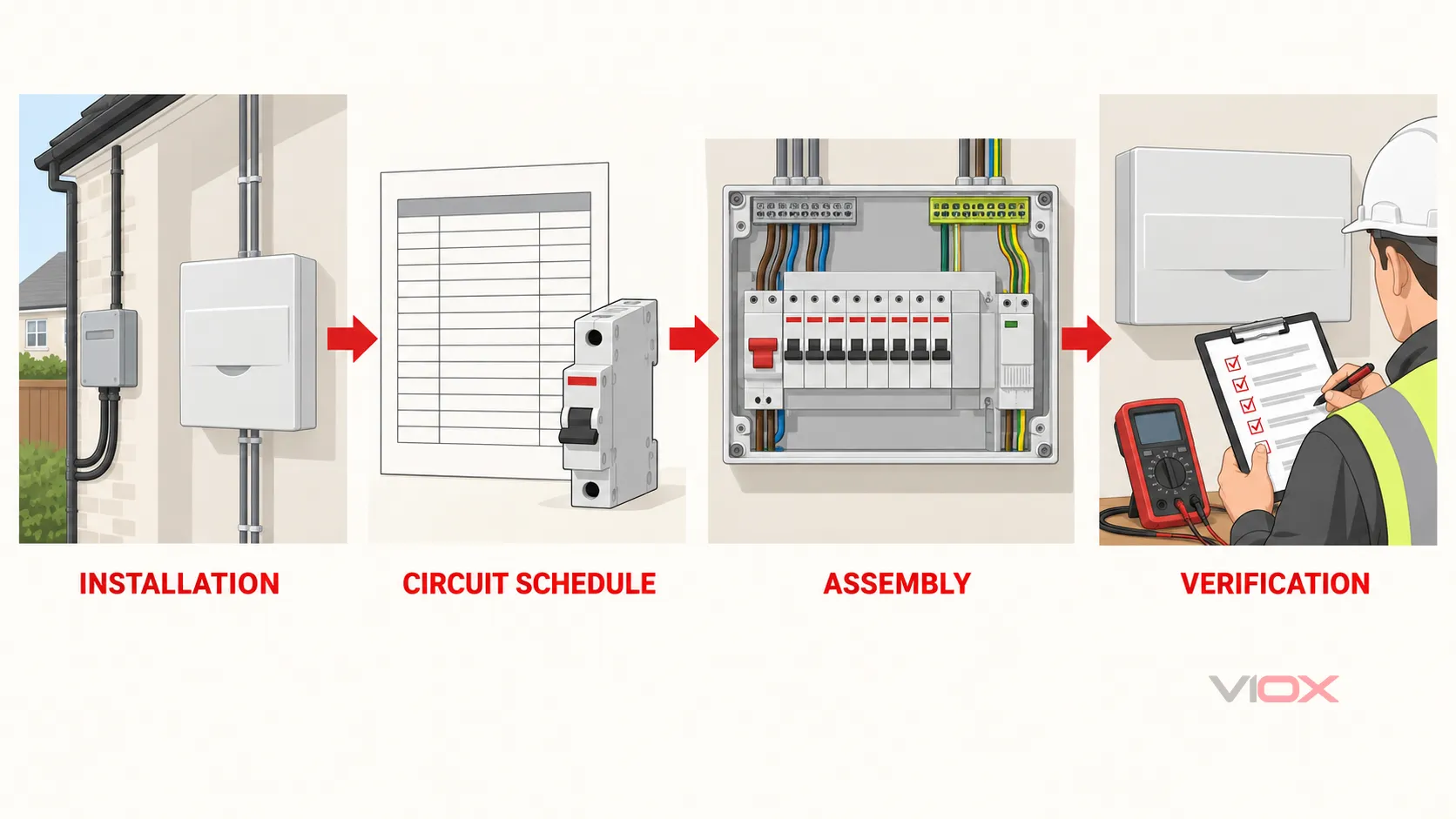
Electrical Safety First’s Best Practice Guides include guidance for replacing consumer units in domestic premises, including pre-work assessment. The detailed VIOX old fuse box to RCBO consumer unit guide covers the assessment, selection, and commissioning sequence without treating the work as a box swap.
Commissioning should follow the applicable installation rules and project documents. It normally requires more than operating the test button: the completed work and circuits need the inspections, instrument tests, functional checks, labels, schedules, and certification required in that jurisdiction.
Technical References
- IEC 61439-3:2024 — Distribution boards intended to be operated by ordinary persons
- IEC 61009-1:2024 — RCBO general rules
- IEC 62423 — Type F and Type B residual-current devices
- Electrical Safety First — Best Practice Guides
- GOV.UK — Approved Document P: Electrical safety in dwellings
Once the board-level and circuit-level schedules are complete, compare the required devices with the documented VIOX RCBO range. Send the destination market, circuit schedule, fault-current basis, assembly constraints, required approvals, and quantity to [email protected] for a model-document review.