
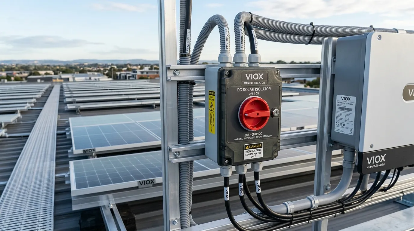
A DC isolator switch is a manually operated disconnect device used in photovoltaic (PV) systems to safely isolate the DC side of an installation for maintenance, servicing, emergency response, and shutdown procedures. It creates a deliberate, clearly indicated disconnection point between solar panels and downstream equipment such as combiner boxes, charge controllers, and inverters.
In practical terms, a DC isolator switch is the device that lets a technician deliberately stop DC power from flowing through the system. It is not an overcurrent protective device, and it is not just another on-off accessory. Its real job is to provide a safe, intentional isolation point in a circuit that remains energized whenever sunlight is present.
That distinction matters because the DC side of a solar installation behaves differently from conventional AC building circuits. Solar modules continue generating voltage in daylight, and DC arcs are harder to interrupt than AC arcs because they do not benefit from natural current zero-crossing. This is why isolator selection, placement, and voltage rating matter so much in PV system design.
Key Takeaways
- A DC isolator switch is primarily used for manual isolation, not automatic fault protection.
- Its most important role is creating a verified disconnection point between the PV array and downstream equipment such as combiner boxes and inverters.
- In solar PV systems, placement matters just as much as device selection. Where you install the isolator directly affects maintenance safety and code compliance.
- A DC isolator switch must be chosen for the actual PV DC voltage, current, and switching duty, not by superficial similarity to an AC disconnect.
- In most multi-string solar installations, the DC isolator switch works alongside breakers or fuses rather than replacing them.
What Does a DC Isolator Switch Do? The Direct Answer
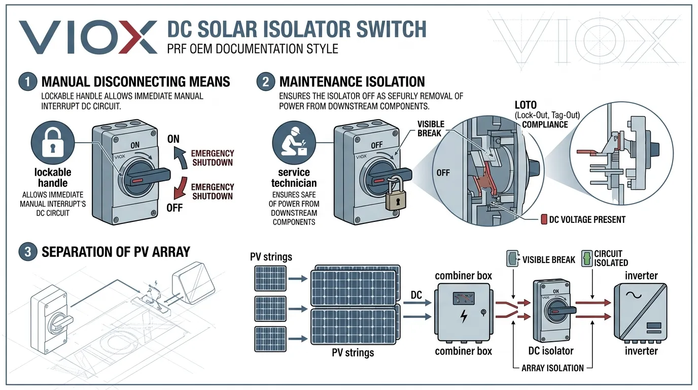
A DC isolator switch performs three core functions in a solar PV system:
- Provides a manual disconnecting means on the PV DC side so technicians can safely de-energize equipment before working on it.
- Supports safe servicing and shutdown procedures by creating a clearly indicated and verified open state that proves the circuit has been intentionally isolated.
- Separates the PV array from downstream equipment such as combiner boxes, charge controllers, or inverters during maintenance, inspection, or emergency response.
In code terms, this falls under the broader requirement for a disconnecting means in photovoltaic systems. In NEC-based projects, this requirement sits within NEC Article 690.13 — Photovoltaic System Disconnecting Means. In IEC- and AS/NZS-based practice, the same concept appears in PV isolation rules governing array-side and inverter-side disconnection under IEC 60364-7-712 and AS/NZS 5033.
The critical distinction is that a DC isolator switch is a device selected for isolation duty, not overcurrent protection. Its safe operating use still depends on the actual switch-disconnector rating, DC utilization category, and project shutdown procedure.
What Makes a DC Isolator Switch Different from an AC Switch?
A PV DC isolator switch is not simply a household or industrial AC switch applied to a higher voltage. It must handle the specific electrical realities of DC switching under solar conditions, which are fundamentally different from AC switching.
The Zero-Crossing Problem
In AC circuits, current naturally passes through zero 100 or 120 times per second, depending on whether the supply is 50 Hz or 60 Hz. When switch contacts open, any arc that forms is helped by the next zero-crossing, typically within a few milliseconds.
DC current has no zero-crossing. Once an arc strikes between opening contacts in a DC circuit, it can sustain itself as long as the source continues to drive current. This means a DC isolator switch requires more robust contact design, wider contact separation, and often arc-management features suited to the actual DC switching duty.
Other DC-Specific Challenges
Beyond arc behavior, a DC isolator switch in a PV system must also contend with:
- continuous DC voltage during daylight, because the array cannot be turned off in the same way as an AC supply
- possible backfeed from connected equipment, depending on the inverter, storage architecture, and parallel paths
- outdoor environmental stress, including UV radiation, rain, dust, temperature cycling, and in some regions salt spray
- long service-life expectations, because PV systems are typically designed for decades of operation
How DC Isolator Switches Are Specified
Because of these challenges, PV DC isolator switches are selected by a specific set of parameters that go well beyond what an AC switch requires:
| Parameter | Why It Matters for DC |
|---|---|
| Rated DC voltage (Ue) | Must exceed maximum system Voc including cold-temperature correction |
| Rated current (Ie) | Must handle continuous PV operating current with appropriate derating |
| Number of poles | Determines how many conductors are simultaneously disconnected |
| Utilization category | DC-21B or DC-22B per IEC 60947-3 indicates actual DC switching capability |
| Enclosure rating (IP) | IP65 or higher for outdoor PV installations exposed to weather |
| Mechanical endurance | Number of rated operating cycles before contact degradation |
For North American installations, projects should look for devices evaluated under UL 98B or equivalent suitability. In Australia and New Zealand, Energy Safe Victoria and AS/NZS 5033 place particular emphasis on DC isolator switch safety because historical isolator failures have been linked to rooftop PV fires.
Why DC Isolation Matters So Much in Solar PV Systems
The DC side of a solar installation creates a safety scenario that does not exist in conventional building electrical systems: the source cannot be turned off.
As long as irradiance is available, PV modules continue generating voltage. That means:
- the inverter may be off
- the main AC disconnect may be open
- the building supply may be completely disconnected
and yet the PV conductors between the array and the inverter can still be live.
This persistent energization is the fundamental reason DC isolator switches exist in PV systems. Without a dedicated, manually operated disconnect point, there is no clear way to isolate the DC conductors for service work.
The Safety Roles of a DC Isolator Switch
Maintenance isolation. Before replacing an inverter, re-torquing combiner box connections, or swapping a surge protective device, a technician must confirm that DC conductors are de-energized. The DC isolator switch supports that process by providing a clear and intentional disconnect point rather than relying only on the handle position of a protective device.
Emergency shutdown. In fire or emergency situations, first responders need a clearly marked, easy-to-operate disconnect point. A red-handled DC isolator switch with clear labeling is immediately recognizable. A row of miniature circuit breakers inside a sealed enclosure is not.
Lockout/tagout support. Many DC isolator switches are designed with padlockable handles that can be locked in the open position. This allows a technician to physically prevent re-energization while working on the system, subject to the applicable local safety procedure.
Firefighter safety. Energy Safe Victoria specifically describes a DC isolator switch as a manual disconnection switch that stops electricity generated by a PV system flowing through the system to make it safer for emergency situations or servicing. That language keeps the role clear: it is there to stop flow intentionally, not to wait for a fault and trip automatically.
Field note from published safety investigations: Energy Safe Victoria has repeatedly highlighted moisture-affected rooftop DC isolators as a real fire cause in older PV installations. That is a useful reminder that isolator selection is only half the job. Placement, sealing, gland entry, and long-term outdoor durability are just as important as the switch rating on the datasheet.
How Rapid Shutdown Fits In
In North American rooftop PV work, NEC 690.12 Rapid Shutdown now sits alongside the traditional disconnecting-means discussion. That is important because some designers assume rapid shutdown has made the DC isolator irrelevant. It has not.
Rapid shutdown and DC isolation solve related but different problems:
- rapid shutdown reduces shock risk on specified conductors in or on buildings after shutdown is initiated
- the DC isolator or disconnecting means provides a deliberate local switching point for maintenance isolation and service workflow
The NFPA material on 690.12 is also useful here because it makes clear that the NEC does not require one single device type to perform the rapid shutdown function. Depending on the system, that function may be handled at module level, array level, or through other listed equipment. In practice, that means rapid shutdown does not automatically eliminate the need for a clear local DC-side isolating means.
Where Is a DC Isolator Switch Installed in a Solar PV System?
The exact installation location depends on the project standard, equipment architecture, system size, and jurisdiction. However, the placement logic follows a consistent principle:
the DC isolator switch goes where technicians need a safe, accessible, and code-compliant disconnection point.
Location 1: Adjacent to or Integrated with the Inverter
The most common DC isolator switch location is near the inverter input. This placement gives technicians a local DC-side disconnect immediately before the inverter, allowing safer de-energization of the inverter’s DC terminals before service work.
Many modern string inverters integrate the DC isolator switch directly into the inverter housing. This integrated approach is increasingly preferred in some markets because it reduces exposed external terminations, eliminates extra enclosure penetrations, and removes a common outdoor failure point.
Energy Safe Victoria has explicitly discussed this direction in its DC isolator safety guidance, noting that integrated isolators can reduce the number of components exposed to weather-related degradation.
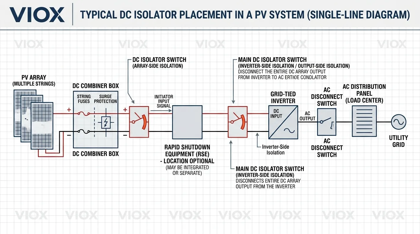
Location 2: At the Combiner Box Output
In systems using combiner boxes, the output side of the combiner box is a natural location for a DC isolator switch. This allows the combined output of all PV strings to be separated from the downstream cable run to the inverter.
In this configuration, the DC isolator switch at the combiner output often serves as the single local disconnection point for the entire combiner box. A technician can open and lock one isolator to isolate the downstream path, rather than relying only on individually opening every string protective device inside the box.
For more on the combiner box context, the solar combiner box explainer and the combiner box product page provide the relevant equipment background.
Location 3: Array-Side or Rooftop Isolation Point
Some project standards and regional codes require or encourage an array-side DC isolator switch in addition to the inverter-side disconnect. This is especially common in rooftop PV installations where the cable run from array to inverter passes through accessible areas.
The purpose of an array-side isolator is to allow disconnection closer to the source. However, the exact requirement varies by jurisdiction, and the preferred approach has evolved over time because rooftop-mounted isolator switches themselves have also become a reliability concern in some markets.
The Placement Principle That Matters Most
Rather than asking “where can I fit the switch?”, the better design question is:
Where does the project need a safe, accessible, and code-acceptable DC disconnecting means?
That answer depends on service workflow, inspection requirements, combiner box architecture, inverter arrangement, cable routing, and the governing electrical code. In many installations, the answer is more than one location.
What a DC Isolator Switch Does Not Do
This is where confusion causes real engineering errors.
A DC isolator switch does not perform the job of a DC circuit breaker or fuse. Specifically:
- it does not automatically detect overcurrent conditions
- it does not trip on short circuit by itself
- it does not provide per-string fault protection
- it does not replace a properly engineered overcurrent protection strategy
A DC isolator switch is selected for disconnecting and isolation duty. Whether it can be operated under load depends on its actual rating and utilization category. It should not be treated as though any isolator can safely interrupt any live PV fault current simply because it opens the circuit.
This is why most PV systems use a layered protection arrangement:
- DC isolator switch for manual disconnecting duty and isolation
- DC circuit breakers or fuses for automatic overcurrent protection
- surge protective devices (SPDs) for transient overvoltage protection where required
Each layer addresses a different failure mode. None of them replaces the others.
DC Isolator Switch vs DC Circuit Breaker: Understanding the Difference
One of the most common questions in PV system design is whether a DC isolator switch and a DC circuit breaker are interchangeable. They are not.
| Feature | DC Isolator Switch | DC Circuit Breaker |
|---|---|---|
| Primary function | Manual isolation and disconnection | Automatic overcurrent detection and interruption |
| Trip mechanism | None — manual operation only | Yes — thermal, magnetic, or electronic trip |
| Designed for load breaking? | Depends on the actual switch-disconnector rating and utilization category | Yes, within the device’s rated DC protective duty |
| Isolation confidence for service | Usually stronger because the device is chosen specifically for isolation duty | Depends on the device, its accessories, and whether it is accepted as the disconnecting means |
| Lockout/tagout capability | Often padlockable in the open position | Sometimes possible with accessories, but not always the preferred service isolator |
| Per-string selectivity | No — provides circuit isolation | Yes — can protect individual strings or groups depending on architecture |
| Typical PV location | Inverter-side, combiner output, or array-side disconnect | Inside combiner box, one per string or string group, or at a feeder protection point |
| Can it replace the other? | No, not for overcurrent protection | Not automatically, and only where listing and application allow it |
The last row is the essential takeaway. A circuit breaker may be accepted as a disconnecting means in some specific configurations if its listing and application explicitly allow it, but that must be verified against the applicable code. Likewise, a DC isolator switch is not an overcurrent protective device regardless of its current rating.
For a deeper dive into this boundary, particularly in the combiner box context, see DC Isolator vs DC Circuit Breaker in Solar Combiner Boxes.
If you are evaluating actual device options rather than the role itself, the VIOX DC Isolator Switch product page is the most relevant product reference.
A Practical PV System Example
Consider a 200 kW commercial rooftop solar installation with eight combiner boxes, each aggregating ten strings. Here is how DC isolator switches and circuit breakers often work together in this kind of architecture:
Inside each combiner box:
- string-level overcurrent protection, which may be implemented with DC circuit breakers or fuses depending on the design basis
- one DC isolator switch or equivalent disconnecting means on the combiner output to provide a local service isolation point
At the inverter:
- one DC isolator switch, integrated or adjacent, providing a final disconnection point before the inverter input
- rapid shutdown equipment or module-level shutdown architecture where the rooftop building code path requires it
During normal operation: the isolator switches remain closed. They are passive until a human operates them. The circuit breakers or fuses handle automatic protection.
During a fault on one string: the relevant overcurrent protective device operates automatically. Reverse current from the remaining strings is interrupted quickly enough to protect the affected conductors. The combiner output isolator remains closed unless maintenance is required.
During scheduled maintenance: the technician opens and locks the combiner output isolator, verifies the disconnect state according to the maintenance procedure, and then isolates the rest of the box as required for the specific work.
This layered approach, automatic protection from breakers or fuses and manual isolation from the DC isolator switch, is standard good practice in many commercial and utility-scale PV installations.
Common DC Isolator Switch Selection Mistakes in Solar PV
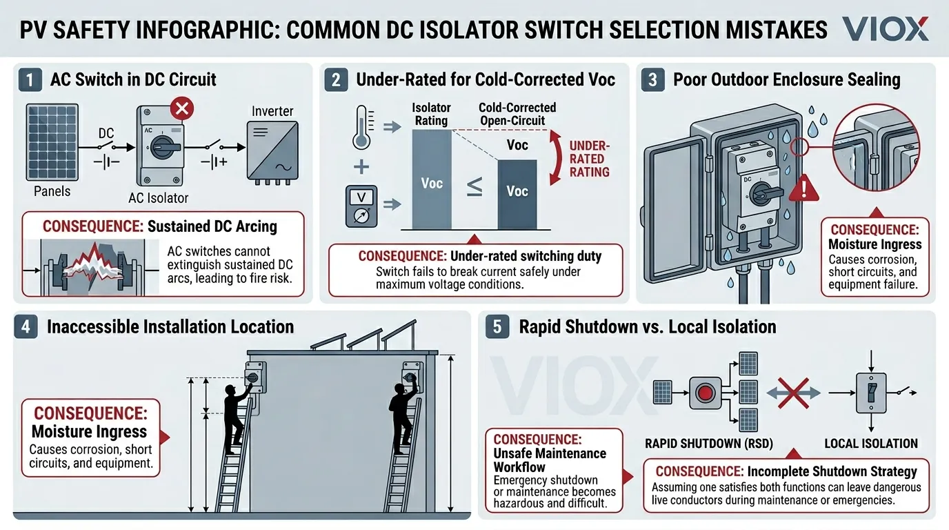
Mistake 1: Using an AC Switch for a DC PV Circuit
This is the most dangerous error and the one with the most severe consequences. AC switches rely on zero-crossing arc extinction that does not exist in DC circuits.
Rule: Every DC isolator switch in a PV system must be explicitly rated and certified for DC duty at the actual system voltage.
Mistake 2: Selecting Based on Nominal Voltage Without Cold-Temperature Correction
PV string open-circuit voltage (Voc) increases as module temperature decreases. A string selected on nominal system voltage alone may exceed the device rating under cold conditions.
Always calculate the maximum corrected Voc using the module datasheet temperature coefficient and the lowest expected ambient temperature at the site, then select an isolator rated above that value.
Mistake 3: Ignoring Enclosure and Environmental Protection
Outdoor PV equipment endures UV radiation, rain, dust, condensation, temperature cycling, and in some regions salt spray. A DC isolator switch with an inadequate IP rating or poor-quality enclosure seals will degrade over time.
For outdoor PV installations, many projects use IP65 as a minimum reference point, with higher ratings considered for harsher environments.
Mistake 4: Placing the Isolator Where It Cannot Support Real Service Work
A DC isolator switch that is technically installed but mounted in an inaccessible location fails its primary purpose. The device exists so a technician can safely and quickly isolate the DC circuit.
Design for the service workflow, not just the electrical one-line diagram.
Mistake 5: Treating the Isolator as the Entire DC Protection Strategy
A DC isolator switch provides isolation. It does not provide overcurrent protection, surge protection, or ground-fault detection.
The isolator is one layer. It needs the other layers alongside it.
Mistake 6: Using Low-Quality Components to Save Cost
DC isolator switches are safety-critical devices that must perform reliably for years in outdoor environments. Low-cost, uncertified, or off-brand isolators may pass initial installation inspection but fail later in service.
For critical PV safety components, a small unit-cost saving is rarely worth the safety or warranty risk.
When Integrated Inverter Isolators Make Sense
The trend toward inverter-integrated DC isolator switches has accelerated in several markets, driven by both safety data and practical installation benefits.
Advantages of integrated isolators:
- fewer exposed outdoor terminations and junction points
- reduced enclosure penetrations that can become moisture ingress points
- simplified installation with fewer separate components to mount and wire
- lower probability of some failure modes associated with standalone outdoor isolator enclosures
When a separate external isolator is still necessary:
- systems with combiner boxes located far from the inverter, where an additional isolation point at the combiner output is needed
- installations where the inverter does not include an integrated DC isolator that meets the local code requirement
- projects requiring array-side isolation per regional standards
- retrofit or replacement scenarios where the existing inverter lacks integrated isolation
The design decision is not “integrated vs external” as a universal rule. It is about matching the isolation architecture to the project’s code requirements, physical layout, and service access needs.
How to Choose the Right DC Isolator Switch for Your PV System
Step 1: Determine Maximum System Voltage
Calculate the maximum open-circuit voltage of the PV string at the lowest expected temperature. Apply the module manufacturer’s temperature coefficient for Voc. Select a DC isolator switch rated at or above this corrected maximum.
Step 2: Verify Current Rating
The isolator must be rated for the maximum continuous current it will carry. In a combiner box application, this may be the combined current of the relevant strings with the applicable design margin.
Step 3: Confirm DC Utilization Category
Look for certification to IEC 60947-3 with a DC utilization category explicitly stated, such as DC-21B or DC-22B, depending on the intended duty. A device certified only for AC utilization categories is not suitable for PV DC isolation regardless of its voltage or current rating.
Step 4: Match Enclosure Protection to Installation Environment
For outdoor installations, confirm that the enclosure protection and material are suitable for UV exposure, moisture, dust, and the site’s real environmental conditions.
Step 5: Verify Certification and Standards Compliance
- IEC 60947-3 for many international markets
- UL 98B for North American PV applications where applicable
- AS/NZS 60947.3 together with AS/NZS 5033 expectations in Australia and New Zealand
Avoid devices that show only AC certifications with a footnote suggesting “suitable for DC.” That is not equivalent to DC-specific testing and certification.
FAQ
What is the main function of a DC isolator switch in a solar system?
The main function is to provide a manual DC disconnecting means so the PV side of the system can be isolated for service, shutdown, or emergency procedures.
Is a DC isolator switch the same as a DC circuit breaker?
No. A DC isolator switch is a manual isolation device with no automatic trip mechanism. A DC circuit breaker is an automatic overcurrent protective device that detects faults and interrupts current without human intervention.
Where should a DC isolator switch be installed in a PV system?
The most common locations are adjacent to or integrated with the inverter, at the combiner box output, or at a code-required array-side disconnect point. The exact placement depends on the governing electrical code, system architecture, and service access requirements.
Can I use a standard AC disconnect switch as a DC isolator?
No. AC switches rely on natural current zero-crossing to help extinguish arcs during switching. DC circuits have no zero-crossing, so a DC arc can sustain across AC-rated contacts. Always use a device explicitly rated and certified for DC duty at the actual system voltage.
Why is DC isolation harder than AC switching?
Because DC arcs do not self-extinguish in the same way as AC arcs. In an AC circuit, current naturally passes through zero many times per second. DC current flows continuously in one direction with no zero-crossing, so switching duty and device suitability become much more important.
How often should a DC isolator switch be tested?
For commercial and utility-scale PV installations, annual inspection and operational testing are common practice. Residential systems are often inspected less frequently. The exact interval should follow the owner’s maintenance program, site conditions, and local requirements.
What voltage rating do I need for a 1000 V solar system?
You need a DC isolator switch rated above the maximum open-circuit voltage of the PV string at the coldest expected temperature, not just the nominal system voltage.
Does every solar PV system legally require a DC isolator switch?
PV systems generally require a disconnecting means on the DC side under most electrical codes, but the exact implementation varies by jurisdiction. In some system configurations, the disconnecting means may be integrated into other equipment. A dedicated DC isolator switch remains one of the clearest and most widely accepted approaches.
Does NEC rapid shutdown replace the need for a DC isolator?
No. Rapid shutdown under NEC 690.12 and DC isolation do not serve exactly the same purpose. Rapid shutdown is about reducing shock risk on specified conductors in building-mounted PV systems. A DC isolator or other disconnecting means is still relevant to local maintenance isolation and service procedure unless the overall equipment arrangement clearly covers that role.
Sources and Standards Referenced
- NEC Article 690.13 — Photovoltaic System Disconnecting Means (NFPA)
- NEC Article 690.12 — Rapid Shutdown of PV Systems on Buildings (NFPA material)
- Energy Safe Victoria — Safety of DC Isolators in PV Systems
- Energy Safe Victoria — PV DC Isolators and Systems Guidance
- IEC 60947-3 — Low-Voltage Switchgear: Switches, Disconnectors, Switch-Disconnectors
- UL 98B — Enclosed and Dead-Front Switches for Use in Photovoltaic Systems
- AS/NZS 5033 — Installation and Safety Requirements for Photovoltaic Arrays
