
Industrial control panels serve as the central nervous system of modern manufacturing and automation systems. These sophisticated electrical assemblies house critical components that monitor, control, and protect industrial equipment across diverse applications—from automated production lines to HVAC systems and power distribution networks. Understanding the components within these panels is essential for engineers, facility managers, and procurement professionals seeking to optimize system performance, ensure safety compliance, and minimize operational downtime.
Key Takeaways
- Control panels integrate essential electrical components including circuit breakers, PLCs, contactors, and transformers to manage industrial automation systems
- Component selection directly impacts system reliability, safety compliance (UL 508A, IEC 61439), and total cost of ownership
- Proper wire management and layout design can reduce troubleshooting time by up to 50% and prevent costly electrical failures
- Understanding SCCR ratings is critical—the lowest-rated component determines the entire panel’s short circuit protection capability
- Modern control panels require careful consideration of power distribution, heat dissipation, and electromagnetic compatibility for optimal performance
What Is an Industrial Control Panel?
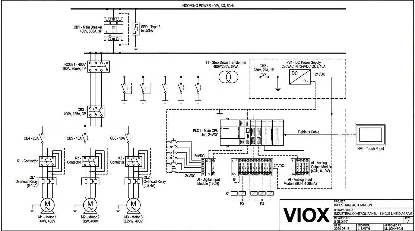
An industrial control panel is a custom-engineered assembly of electrical devices designed to manage, monitor, and control industrial equipment and processes. According to the National Electrical Code (NEC) Section 409.2, an industrial control panel is defined as “an assembly of two or more power circuit components, control circuit components, or any combination of power and control circuit components.”
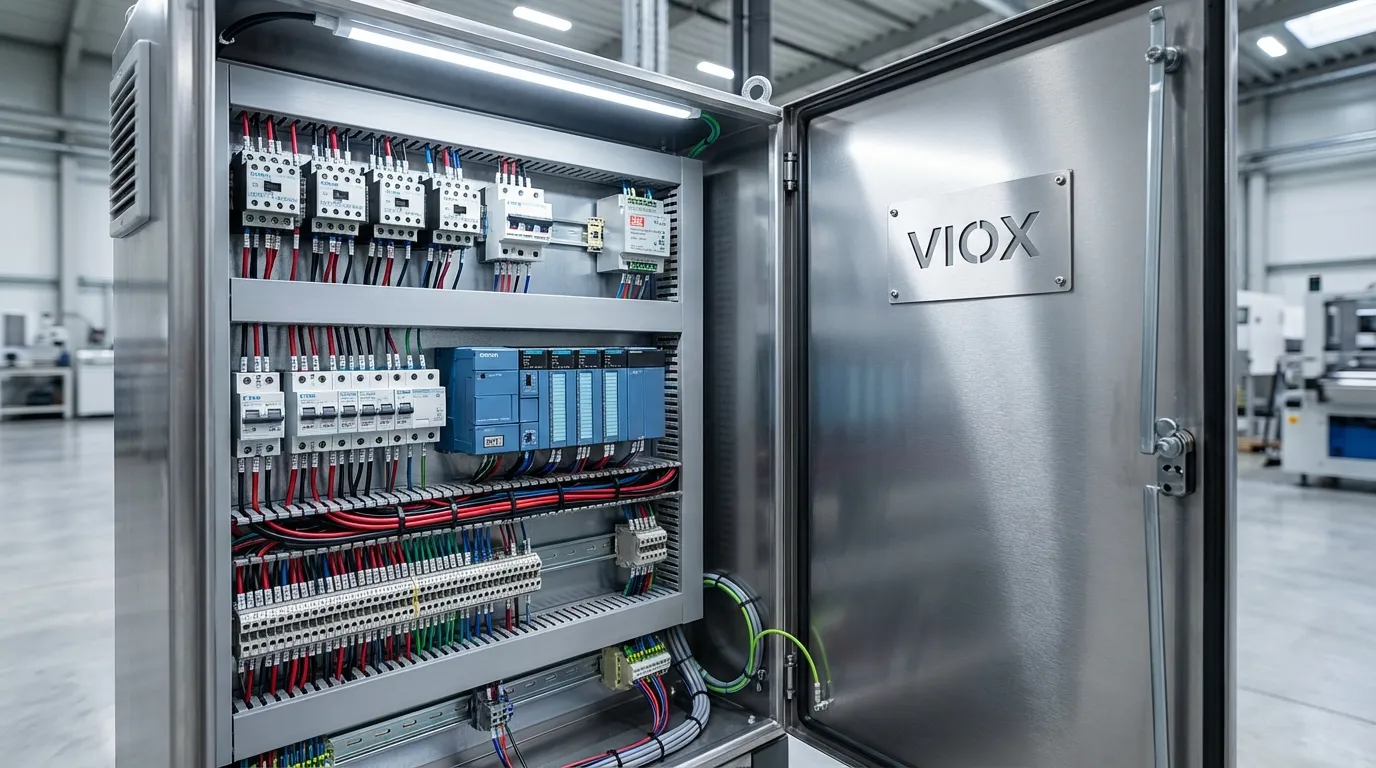
These panels consolidate switches, indicators, relays, circuit breakers, transformers, and terminal blocks into a single protective enclosure, enabling efficient control of complex machinery. Control panels range from simple electrical control panels with basic switching functions to highly sophisticated industrial control panels featuring programmable logic controllers (PLCs) and human-machine interfaces (HMIs) for advanced automation.
The primary functions of industrial control panels include:
- Power distribution and management across multiple circuits and devices
- Process automation through programmable logic and sequential control
- System monitoring via sensors, meters, and diagnostic displays
- Safety protection against electrical faults, overloads, and short circuits
- Operator interface for manual control and system status visibility
Essential Control Panel Components
1. Circuit Protection Devices
Circuit protection forms the foundation of safe control panel operation, safeguarding both equipment and personnel from electrical hazards.
Miniature Circuit Breakers (MCBs)
MCBs provide overcurrent protection for control circuits operating at 120V–480V in most industrial applications. These compact devices automatically interrupt current flow when detecting overload conditions or short circuits. MCBs feature both thermal (overload) and magnetic (short circuit) trip mechanisms, with breaking capacities typically ranging from 6kA to 10kA.
Molded Case Circuit Breakers (MCCBs)
For higher current applications, MCCBs handle 15A to 2500A with adjustable trip settings. These robust devices protect main power feeds and large motor circuits. Modern MCCBs may include electronic trip units with ground fault protection and communication capabilities for predictive maintenance.
Residual Current Circuit Breakers (RCCBs)
RCCBs detect earth leakage currents and provide critical protection against electric shock hazards. These devices are essential in applications where personnel may contact equipment, particularly in EV charging installations where specialized Type B or Type EV RCCBs are required.
Fuses
Industrial fuses provide fast-acting overcurrent protection, particularly for semiconductor devices and sensitive electronics. High Rupturing Capacity (HRC) fuses offer superior breaking performance in high-fault-current environments, while DC fuses are specifically designed for solar PV and battery storage applications.
2. Control and Switching Devices
Contactors and Motor Starters
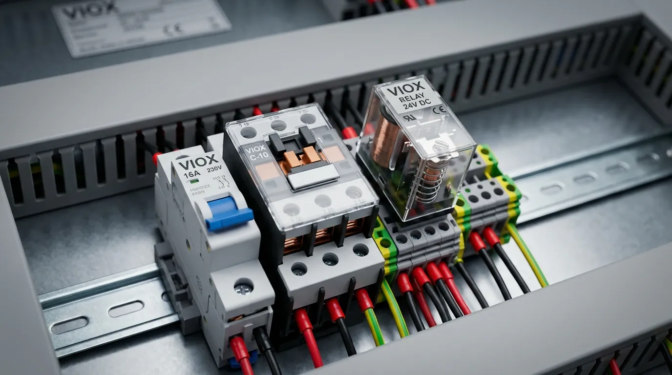
Contactors are electrically operated switches that control high-power loads based on low-voltage control signals. These electromagnetic devices make or break power circuits to motors, heaters, and lighting systems. Modular contactors offer space-saving DIN-rail mounting for residential and light commercial applications, while traditional contactors handle industrial motor control duties.
Motor starters combine contactors with overload protection relays, providing complete motor control and protection in a single assembly. The selection between AC-1, AC-3, and AC-4 utilization categories depends on the specific motor application and duty cycle.
Relays
Relays serve as interface devices between control circuits and power circuits, isolating low-voltage control signals from high-voltage loads. Control panels typically incorporate several relay types:
- Control relays for logic functions and interlocking
- Time delay relays for sequential operations and pump protection
- Thermal overload relays for motor protection
- Voltage monitoring relays for power quality surveillance
Push Buttons and Selector Switches
Manual control devices provide operator interface for starting, stopping, and mode selection. Emergency stop buttons must be readily accessible and comply with safety standards, featuring positive-opening contacts that ensure circuit interruption even in case of contact welding.
3. Programmable Logic Controllers (PLCs)
PLCs function as the “brain” of modern industrial control panels, executing programmed logic to automate processes and coordinate equipment operation. These industrial-grade computers accept inputs from sensors and switches, process logic according to programmed instructions, and control outputs to actuators, motors, and indicators.
Modern PLCs offer:
- Scalable I/O configurations from compact units to large distributed systems
- Multiple communication protocols including Ethernet/IP, Modbus, and Profibus
- Built-in diagnostics for rapid troubleshooting
- Hot-swappable modules for minimal downtime during maintenance
PLCs have largely replaced relay logic in industrial applications due to their flexibility, reliability, and ease of programming modifications.
4. Human-Machine Interfaces (HMIs)
HMIs provide graphical operator interfaces for monitoring system status, adjusting parameters, and diagnosing faults. These touchscreen displays or panel-mounted terminals enable operators to interact with PLCs and other control devices without requiring programming knowledge. Modern HMIs feature:
- Real-time data visualization with trending and alarming
- Recipe management for product changeovers
- Remote access capabilities for off-site monitoring
- Multi-language support for global operations
5. Power Distribution Components
Transformers
Control panel transformers convert incoming line voltage (typically 480V or 240V AC) to lower control voltages (120V or 24V AC) required by control devices, PLCs, and indicating lights. Proper transformer sizing must account for inrush currents and continuous VA ratings of all connected loads.
Power Supplies
Switching power supplies convert AC voltage to regulated DC voltage (commonly 24V DC) for powering PLCs, sensors, and solid-state devices. Industrial power supplies must withstand voltage fluctuations, provide overcurrent protection, and maintain regulation under varying load conditions.
Busbars and Distribution Blocks
Busbars efficiently distribute power throughout the panel, reducing wire clutter and improving current-carrying capacity. Power distribution blocks provide multiple connection points from a single input source, simplifying wiring for parallel circuits.
6. Surge Protection Devices (SPDs)
Surge protective devices safeguard sensitive electronics from transient overvoltages caused by lightning strikes, switching operations, or utility disturbances. Type 1, Type 2, and Type 3 SPDs provide coordinated protection at service entrance, distribution, and equipment levels respectively. Proper SPD selection requires understanding MCOV ratings and system grounding configuration.
7. Terminal Blocks and Wiring Infrastructure
Terminal Blocks
Terminal blocks provide organized, accessible connection points for field wiring and internal panel connections. Various types serve different functions:
- Feed-through terminals for simple wire-to-wire connections
- Fused terminal blocks combining connection and protection
- Disconnect terminals allowing circuit isolation without removing wires
- Ceramic terminal blocks for high-temperature applications
DIN Rails
DIN rails provide standardized mounting for modular components, enabling flexible panel layouts and simplified component replacement. The TH35 (35mm) DIN rail has become the industry standard for mounting circuit breakers, relays, terminal blocks, and other control devices.
Wire Ducts and Cable Management
Proper wire routing using wire ducts, cable ties, and cable glands ensures organized wiring that facilitates troubleshooting and maintenance. Well-managed wiring also improves heat dissipation and reduces electromagnetic interference between circuits.
8. Indicating and Monitoring Devices
Pilot Lights and Indicators
LED indicator lights provide visual status feedback for power presence, equipment operation, and alarm conditions. Color-coded indicators follow industry conventions (green for running, red for stopped, amber for alarm conditions).
Meters and Displays
Digital meters monitor voltage, current, power, and energy consumption. Modern multifunction meters provide comprehensive power quality analysis and can communicate data to supervisory systems via Modbus or Ethernet protocols.
Proximity Sensors
Inductive, capacitive, and photoelectric proximity sensors detect object presence without physical contact, enabling automated process control and safety interlocking.
9. Communication and Networking Devices
Ethernet Switches
Industrial Ethernet switches enable network communication between PLCs, HMIs, variable frequency drives (VFDs), and SCADA systems. Managed switches provide VLAN segmentation, quality of service (QoS), and network diagnostics for mission-critical applications.
Protocol Converters
Gateway devices translate between different industrial protocols (Modbus RTU to Modbus TCP, Profibus to Ethernet/IP), enabling integration of legacy equipment with modern control systems.
10. Enclosures and Environmental Protection
The control panel enclosure provides physical protection for components while meeting environmental requirements. NEMA and IP ratings specify protection levels against dust, moisture, and physical impact. Enclosure selection must consider:
- Operating environment (indoor, outdoor, hazardous locations)
- Temperature control (ventilation, air conditioning, heaters)
- Accessibility for operation and maintenance
- Material selection (stainless steel vs. aluminum for corrosive environments)
Control Panel Component Comparison Table
| Component Type | Primary Function | Typical Voltage Range | Key Selection Criteria | Common Applications |
|---|---|---|---|---|
| MCB | Overcurrent protection | 120-480V AC | Breaking capacity (kA), trip curve (B, C, D) | Lighting, control circuits, small motors |
| MCCB | High-current protection | 120-690V AC | Current rating (15-2500A), adjustable trip | Main feeders, large motors, distribution |
| RCCB | Earth leakage protection | 120-480V AC | Sensitivity (30mA, 100mA, 300mA), Type (AC, A, B) | Personnel protection, equipment grounding |
| Contactor | Load switching | 120-690V AC/DC | Utilization category (AC-1, AC-3), coil voltage | Motor control, heating, lighting |
| Relay | Signal isolation/control | 12-240V AC/DC | Contact configuration (SPDT, DPDT), coil type | Interlocking, logic, interface |
| PLC | Process automation | 24V DC (I/O) | I/O count, memory, communication protocols | Manufacturing, process control, building automation |
| Transformer | Voltage conversion | 120-480V input | VA rating, voltage ratio, regulation | Control power, isolation |
| Power Supply | AC to DC conversion | 120-240V AC input | Output voltage/current, efficiency, hold-up time | PLC power, sensor supply, DC loads |
| SPD | Transient suppression | System voltage | Type (1/2/3), MCOV, discharge current (kA) | Lightning protection, switching surge mitigation |
| Terminal Block | Wire connection | Up to 1000V | Current rating, wire gauge capacity, type | Field wiring, internal connections |
Control Panel Design Standards and Compliance
Industrial control panels must comply with rigorous safety and performance standards to ensure reliable operation and regulatory acceptance.
UL 508A – Industrial Control Panels
UL 508A is the primary standard for industrial control panel construction and certification in North America. This standard establishes requirements for:
- Component selection using UL-listed or recognized devices
- Short Circuit Current Rating (SCCR) calculation and marking
- Wiring methods including conductor sizing, routing, and termination
- Overcurrent protection coordination
- Enclosure selection and environmental ratings
- Marking and documentation requirements
The SCCR represents the maximum fault current the panel can safely withstand. Critically, the lowest-rated component determines the entire panel’s SCCR—a common oversight that can compromise safety and fail inspection.
NFPA 70 (National Electrical Code)
The NEC provides comprehensive requirements for electrical installations, including control panels. Key provisions include:
- Article 409 – Industrial Control Panels
- Article 430 – Motors, Motor Circuits, and Controllers
- Article 670 – Industrial Machinery
- Article 110.26 – Working clearances around electrical equipment
NFPA 79 – Electrical Standard for Industrial Machinery
NFPA 79 addresses electrical equipment of industrial machines operating at 600V or less, providing detailed guidance on wire sizing, color coding, and installation methods specific to machine control panels.
IEC Standards
For international applications, IEC standards provide equivalent requirements:
- IEC 61439 – Low-voltage switchgear and control gear assemblies
- IEC 60204-1 – Safety of machinery – Electrical equipment of machines
- IEC 60947 – Low-voltage switchgear and control gear
CE Marking and EU Directives
Control panels destined for European markets must comply with applicable EU directives and bear CE marking, demonstrating conformity with:
- Low Voltage Directive (LVD) 2014/35/EU
- Machinery Directive 2006/42/EC
- EMC Directive 2014/30/EU
Control Panel Wiring Best Practices
Proper wiring practices directly impact control panel reliability, safety, and maintainability. Well-organized wiring can reduce troubleshooting time by up to 50%, while poor wiring practices lead to premature failures and safety hazards.
Wire Selection and Sizing
Conductor Type
Industrial control panels typically use MTW (Machine Tool Wire) rated for 600V and 90°C. This stranded copper wire provides flexibility for panel wiring while maintaining durability. For field wiring and conduit runs, THHN/THWN conductors are standard.
Wire Gauge Selection
Conductor sizing must account for:
- Continuous current of the connected load
- Ambient temperature and derating factors
- Voltage drop limitations (typically 3% maximum)
- Overcurrent protection device rating
- Bundling and grouping effects on heat dissipation
NFPA 79 provides detailed tables for wire sizing based on these factors. Undersized conductors lead to overheating, insulation degradation, and potential fire hazards.
Color Coding Standards
Consistent wire color coding enhances safety and simplifies troubleshooting:
North American Convention:
- Black, Red, Blue – Line conductors (L1, L2, L3)
- White or Gray – Neutral conductor
- Green or Green/Yellow – Grounding conductor
- Red – Control power (hot)
- Black or Blue – Control power (return)
- Orange – 24V DC positive
- Blue – 24V DC negative
IEC Convention:
- Brown, Black, Gray – Line conductors (L1, L2, L3)
- Blue – Neutral conductor
- Green/Yellow – Protective earth
- Red – Control circuits
- Black – DC negative
- Red – DC positive
Wire Routing and Management
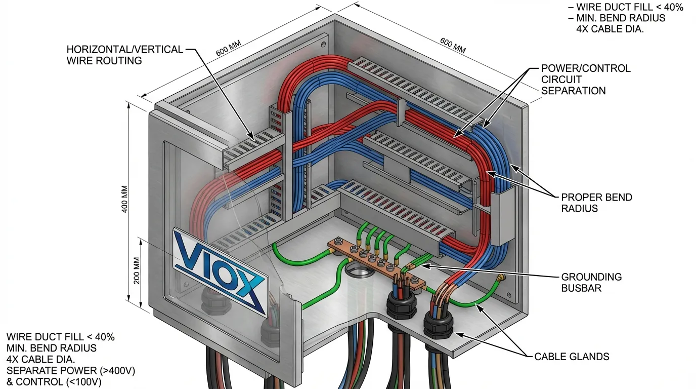
Horizontal and Vertical Routing
Wires should run in horizontal and vertical lines—never diagonally. This organized approach facilitates visual tracing and creates a professional appearance that reflects quality workmanship.
Separation Requirements
Maintain separation between:
- Power and control circuits to reduce electromagnetic interference
- High-voltage and low-voltage wiring for safety
- Input and output circuits to prevent noise coupling
UL 508A specifies minimum separation distances based on voltage levels and circuit types.
Wire Length Optimization
Wires should be just long enough to allow component replacement and maintenance, but not so long as to create tangled “spaghetti” wiring. Excessive wire length increases voltage drop, creates heat buildup in bundles, and complicates troubleshooting.
Bend Radius
Respect minimum bend radius specifications to prevent conductor damage. As a general rule, maintain bend radii of at least 6 times the wire diameter for stranded conductors.
Termination Techniques
Ferrules
Wire ferrules provide professional terminations for stranded wire, preventing strand breakage and ensuring reliable connections in screw terminals. Ferrules are particularly important for fine-stranded wire and in applications subject to vibration.
Torque Specifications
Follow manufacturer-specified torque values for terminal connections. Under-torqued connections create high resistance and heat buildup, while over-torqued connections damage terminals and conductors.
Terminal Block Organization
Group related circuits on adjacent terminals and maintain consistent terminal numbering that corresponds to schematic drawings. This organization dramatically reduces troubleshooting time.
Labeling and Documentation
Wire Identification
Every wire should be labeled at both ends with a unique identifier that corresponds to the control panel schematic. Use durable labels suitable for the operating environment—heat-shrink labels for high-temperature applications, wrap-around labels for general use.
Component Labeling
Label all components with designations matching the schematic (e.g., M1 for motor starter 1, CR5 for control relay 5). This correspondence between physical equipment and drawings is essential for maintenance and troubleshooting.
Drawing Accuracy
Maintain as-built drawings that accurately reflect the installed configuration. Discrepancies between drawings and actual wiring create safety hazards and maintenance nightmares.
Control Panel Layout and Design Considerations
Thoughtful control panel layout enhances functionality, safety, and maintainability while optimizing space utilization.
Component Grouping
Functional Grouping
Organize components by function:
- Power distribution components near the top
- Control logic (PLCs, relays) in the middle section
- I/O terminals near cable entry points
- Operator interface devices on the door or at accessible height
Voltage Segregation
Physically separate high-voltage and low-voltage sections, using barriers or dedicated zones. This separation reduces shock hazards during maintenance and minimizes electromagnetic interference.
Heat Management
Electrical components generate heat during operation. Inadequate heat dissipation leads to premature failure and reduced reliability.
Heat Load Calculation
Calculate total heat generation from all components (particularly power supplies, VFDs, and large contactors). If the calculated internal temperature exceeds component ratings, implement cooling solutions:
- Natural ventilation with properly sized vents
- Forced air cooling using fans and filters
- Air conditioning for high heat loads or extreme ambient conditions
- Heat sinks for high-power semiconductors
Component Spacing
Maintain adequate spacing between heat-generating components to allow air circulation. Cramped layouts trap heat and create hot spots that accelerate component aging.
Accessibility and Maintenance
Service Clearances
Design layouts that allow access to components requiring periodic maintenance or adjustment. Frequently serviced items (fuses, adjustable relays, terminal blocks) should be readily accessible without removing other components.
Door-Mounted Components
Mount operator interface devices (push buttons, selector switches, HMIs, pilot lights) on the enclosure door for easy access. Ensure door-mounted components have sufficient wire length and strain relief to accommodate door opening.
Test Points
Provide accessible test points for voltage measurement and signal monitoring during commissioning and troubleshooting.
Grounding and Bonding
Proper grounding is essential for safety and noise immunity:
- Equipment grounding connects all metal enclosure parts to ground
- Separate grounding bars for power and control grounds (when required)
- Star-point grounding for sensitive analog circuits
- Shielded cable grounding at one end only to prevent ground loops
Common Control Panel Applications
Industrial control panels serve diverse applications across multiple industries:
Motor Control Centers (MCCs)
MCCs consolidate motor starters, VFDs, and associated control devices for multiple motors in a single assembly. These panels are common in manufacturing facilities, water treatment plants, and HVAC systems where numerous motors require centralized control.
PLC Control Panels
PLC panels serve as the automation hub for manufacturing lines, packaging equipment, and process control systems. These panels integrate PLCs, I/O modules, power supplies, and communication devices to execute complex automation sequences.
Distribution Panels
Electrical distribution panels distribute incoming power to multiple branch circuits, incorporating main breakers, branch circuit protection, and metering. These panels range from residential load centers to industrial distribution boards serving entire facilities.
Automatic Transfer Switch (ATS) Panels
ATS panels automatically switch between utility and backup generator power during outages, ensuring continuous operation of critical loads. These panels are essential for hospitals, data centers, and emergency systems.
Solar Combiner Boxes
PV combiner boxes consolidate outputs from multiple solar panel strings, incorporating DC circuit breakers, fuses, and surge protection before feeding the inverter. These specialized panels must withstand outdoor environments and comply with NEC Article 690.
Specialized Control Panels
- HVAC control panels for building automation
- Pump control panels with level controls and alternation
- EV charging stations with specialized protection
- Fire alarm and life safety panels
Selecting the Right Control Panel Components
Component selection directly impacts system reliability, total cost of ownership, and regulatory compliance.
Performance Requirements
Define operational parameters:
- Voltage and frequency of power supply
- Current ratings for all circuits
- Duty cycle (continuous, intermittent, short-time)
- Environmental conditions (temperature, humidity, contamination)
- Control complexity (simple on/off vs. complex automation)
Safety and Compliance
Ensure components meet applicable standards:
- UL listing or recognition for North American installations
- CE marking for European markets
- Appropriate ratings for the application (voltage, current, breaking capacity)
- Environmental ratings matching installation conditions
Quality and Reliability
Consider:
- Manufacturer reputation and track record
- Mean Time Between Failures (MTBF) data
- Warranty terms and technical support availability
- Spare parts availability for long-term maintenance
Total Cost of Ownership
Look beyond initial purchase price:
- Energy efficiency (particularly for power supplies and VFDs)
- Maintenance requirements and intervals
- Expected service life before replacement
- Downtime costs associated with component failures
Supplier Selection
Partner with reputable suppliers like VIOX Electric that offer:
- Comprehensive product portfolios for one-stop procurement
- Technical support for component selection and application
- Quality certifications (ISO 9001, UL, CE)
- Consistent availability and reliable delivery
- Competitive pricing for volume purchases
Troubleshooting Control Panel Issues
Systematic troubleshooting minimizes downtime and identifies root causes rather than symptoms.
Common Control Panel Problems
Nuisance Tripping
Circuit breakers that trip repeatedly may indicate:
- Overloaded circuits requiring load reduction or larger breakers
- Ground faults from damaged insulation or moisture ingress
- Loose connections creating arcing and heat
- Incorrect breaker sizing for the application
Contactor Failures
Contactor problems include:
- Coil burnout from overvoltage or excessive duty cycle
- Contact welding from high inrush currents or inadequate rating
- Mechanical wear requiring replacement
- Buzzing or chattering from low voltage or mechanical binding
Communication Failures
Network communication issues often stem from:
- Loose cable connections at terminals
- Incorrect network configuration (IP addresses, subnet masks)
- EMI interference from unshielded cables or improper grounding
- Failed network switches or modules
Overheating
Excessive heat indicates:
- Inadequate ventilation or blocked vents
- Overloaded components operating beyond ratings
- Poor connections creating high resistance
- Ambient temperature exceeding design limits
Diagnostic Techniques
Visual Inspection
Begin with thorough visual examination:
- Discolored or burnt components indicating overheating
- Loose or corroded connections
- Physical damage to components or wiring
- Indicator lights showing fault conditions
Voltage Measurements
Verify proper voltages at:
- Power supply inputs and outputs
- Control power transformer secondary
- PLC power supply and I/O modules
- Coil voltages on contactors and relays
Current Measurements
Measure actual load currents and compare to:
- Nameplate ratings of connected equipment
- Circuit breaker and wire ampacity ratings
- Expected values based on system design
Thermal Imaging
Infrared cameras identify hot spots indicating:
- Loose connections with high resistance
- Overloaded circuits or components
- Inadequate heat dissipation
Preventive Maintenance
Regular maintenance prevents failures:
- Quarterly inspections of connections, indicators, and physical condition
- Annual testing of protective devices and interlocks
- Cleaning to remove dust and contamination
- Thermal scanning to identify developing problems
- Documentation of findings and corrective actions
Frequently Asked Questions (FAQ)
Q: What is the difference between an electrical control panel and an industrial control panel?
A: An electrical control panel typically contains basic components like circuit breakers, fuses, relays, and transformers for managing electrical devices. An industrial control panel includes these components plus advanced automation devices like PLCs and HMIs for controlling complex industrial processes and machinery. Industrial control panels are specifically designed for automation and process control applications.
Q: How do I calculate the Short Circuit Current Rating (SCCR) for my control panel?
A: The SCCR is determined by the lowest-rated component in the panel. Review the short circuit ratings of all circuit breakers, contactors, relays, and other devices. The component with the lowest interrupting capacity establishes the maximum fault current the panel can safely withstand. This value must be marked on the panel nameplate and must exceed the available fault current at the installation location. For detailed calculations, consult UL 508A Supplement SB or work with a certified panel shop.
Q: What wire size should I use for control panel wiring?
A: Wire sizing depends on the continuous current of the connected load, ambient temperature, bundling factors, and voltage drop considerations. For control circuits operating at 120V AC, 14 AWG (2.5mm²) wire is common for loads up to 15A. Power circuits require larger conductors based on NEC Table 310.16 or NFPA 79 requirements. Always consult applicable codes and apply appropriate derating factors for temperature and bundling.
Q: How often should control panels be inspected and maintained?
A: Perform visual inspections quarterly to check for loose connections, damaged components, and proper operation of indicators. Conduct comprehensive annual maintenance including connection torque checks, thermal imaging, protective device testing, and cleaning. High-duty or critical applications may require more frequent inspection. Document all maintenance activities and findings.
Q: Can I replace a circuit breaker with a higher amperage rating?
A: No. Replacing a circuit breaker with a higher rating without upgrading the wire size creates a serious fire hazard. The circuit breaker must be sized to protect the conductor, not just the load. If the existing breaker trips frequently, investigate the cause (overload, ground fault, or defective breaker) rather than simply increasing the breaker size.
Q: What is the difference between UL 508A and IEC 61439 standards?
A: UL 508A is the North American standard for industrial control panels, focusing on individual panel assemblies and requiring SCCR calculations and specific component selection criteria. IEC 61439 is the international standard covering entire electrical assemblies including switchgear and distribution boards, with different verification methods and type-testing requirements. Panels for the US market require UL 508A compliance, while international markets typically follow IEC standards.
Q: Do I need a PLC for my control panel?
A: PLCs are beneficial when your application requires complex logic, multiple sequences, frequent program changes, or integration with other systems. Simple applications with basic on/off control may be adequately served by relay logic or dedicated controllers. Consider a PLC when you need flexibility, scalability, or advanced features like recipe management, data logging, or remote monitoring.
Q: How do I select the correct contactor for motor control?
A: Contactor selection requires knowing the motor full-load current, starting method (DOL, star-delta, soft start), duty cycle, and control voltage. Choose a contactor with a utilization category matching your application (AC-3 for standard motors, AC-4 for heavy starting duty). The contactor’s rated operational current must exceed the motor full-load current with appropriate safety margin. Verify the coil voltage matches your control power supply.
Conclusion
Industrial control panels represent sophisticated assemblies of electrical and electronic components working together to manage, protect, and automate industrial equipment. Understanding the function and selection criteria for each component—from circuit breakers and contactors to PLCs and communication devices—enables engineers and facility managers to design, specify, and maintain control systems that deliver reliable performance, ensure personnel safety, and comply with applicable codes and standards.
Proper component selection, adherence to wiring best practices, and compliance with UL 508A, NEC, and IEC standards form the foundation of safe and effective control panel design. Whether you’re specifying a new control panel, upgrading existing equipment, or troubleshooting operational issues, a thorough understanding of control panel components and their interactions is essential for success.
For assistance with control panel component selection, custom panel design, or technical support, contact the experts at VIOX Electric—your trusted partner for industrial electrical solutions.
