On this page
Quick Answer: How Do You Choose the Right Terminal Block?
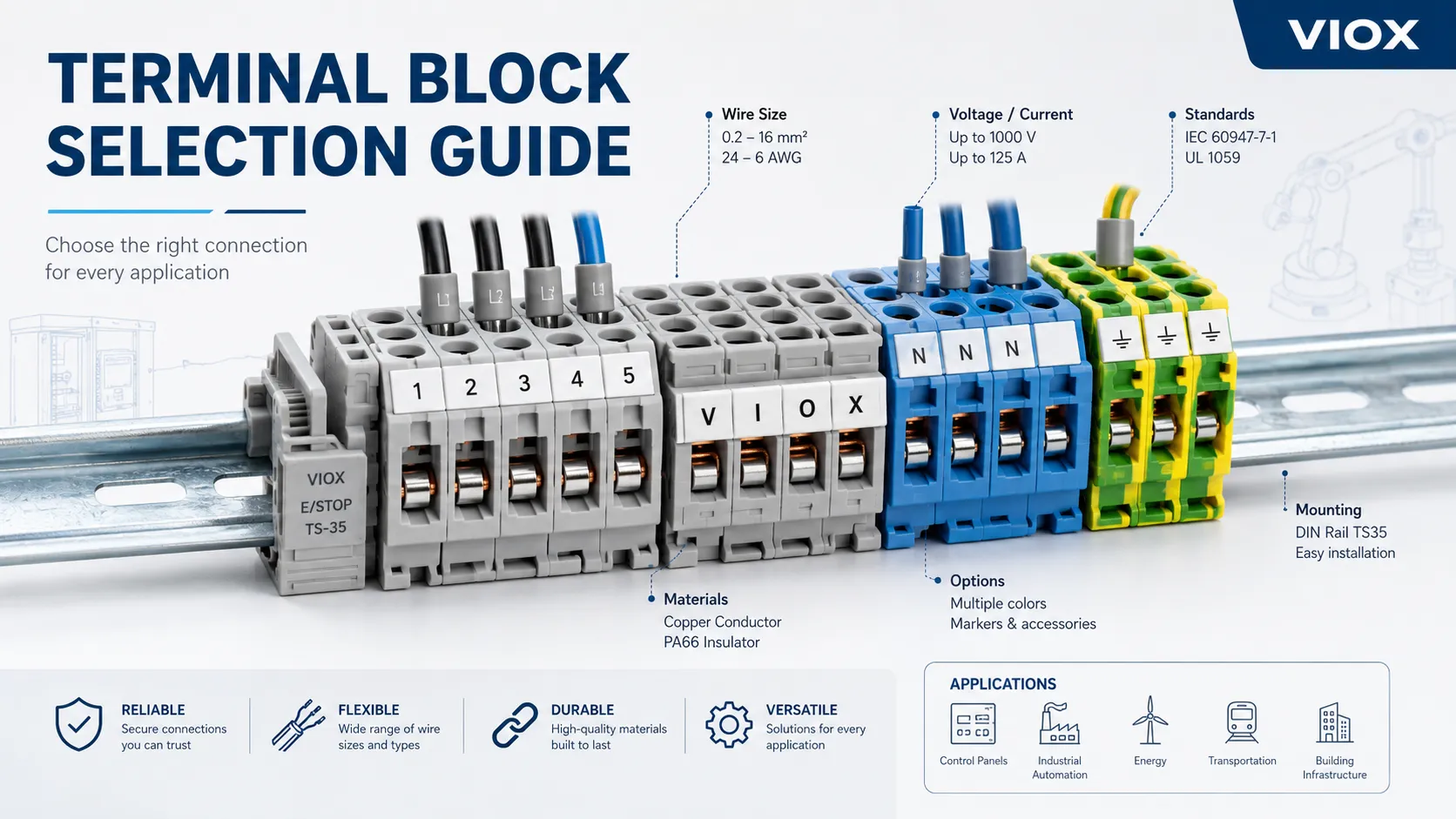
Choose a terminal block by matching the circuit function, connection method, rated current, rated voltage, wire size, conductor type, housing material, mounting method, and required standards. A terminal block is not selected only because the wire fits into the opening. It must maintain stable contact pressure, low contact resistance, adequate creepage and clearance, safe temperature rise, and serviceable wiring layout under the actual conditions of the panel or equipment.
For most industrial control panels, the practical sequence is:
- Define the circuit function: power, control, signal, protective earth, fuse, disconnect, test, or distribution.
- Confirm conductor size in mm² or AWG, conductor class, insulation diameter, and ferrule requirement.
- Check current rating, voltage rating, impulse withstand voltage, conductor range, and temperature-rise data from the datasheet.
- Select the connection technology: screw, spring clamp, push-in, barrier, PCB, stud, or insulation displacement connection.
- Verify relevant standards such as IEC 60947-7-1, IEC 60947-7-2, UL 1059, and panel-level requirements such as UL 508A where applicable.
- Check accessories: jumpers, bridges, markers, end plates, separators, test plugs, and end stops.
If the terminal block is used inside a control panel, treat it as part of the wiring system rather than a small accessory. Many field failures blamed on “bad wiring” start with the wrong terminal block, wrong conductor preparation, or a mismatch between terminal rating and real installation conditions.
Terminal Block Selection Table
| Selection factor | What to check | Why it matters |
|---|---|---|
| Terminal block type | Feed-through, PE/ground, fuse, disconnect, test, barrier, PCB, distribution, multi-level | Determines the circuit function and wiring layout |
| Connection method | Screw, spring clamp, push-in, stud/bolt, IDC | Affects wiring speed, vibration resistance, maintenance, and conductor preparation |
| Rated current | Datasheet rating under stated test conditions | Prevents excessive temperature rise |
| Rated voltage | Working voltage, insulation voltage, impulse withstand voltage | Prevents insulation breakdown and flashover |
| Creepage and clearance | Spacing, pollution degree, material group | Determines insulation suitability for the environment |
| Wire size range | mm²/AWG range, solid/stranded/flexible compatibility | Ensures the conductor is clamped correctly |
| Ferrule requirement | Especially for fine-stranded and flexible conductors | Prevents strand damage and poor insertion |
| Housing material | PA66, PBT, PC, ceramic, thermoset, or specialty material | Affects heat resistance, flame behavior, insulation, and environment fit |
| Metal parts | Copper alloy, brass, plating, clamp geometry | Affects conductivity, corrosion resistance, and contact stability |
| Mounting method | DIN rail, PCB, panel, base, busbar, screw mount | Determines mechanical integration and serviceability |
| Standards and approvals | IEC, UL, CSA, ATEX/IECEx when required | Reduces inspection and compliance risk |
For a broad product reference, see the VIOX terminal block product range. For DIN-rail-specific selection, use the more detailed guide on how to select DIN rail mounted terminal blocks.
What Is a Terminal Block?
A terminal block is an insulated electromechanical connection device used to terminate, join, distribute, or organize conductors. Instead of twisting wires together or making permanent splices, each conductor is inserted into a defined clamping structure. The terminal block provides mechanical retention, electrical continuity, insulation between circuits, and a clear wiring point for inspection or maintenance.
A typical terminal block has three functional parts:
| Part | Function |
|---|---|
| Insulating housing | Separates adjacent circuits and supports the conductive structure |
| Current-carrying element | Provides the electrical path between conductors |
| Clamping mechanism | Holds the conductor against the conductive element with stable contact pressure |
In industrial panels, terminal blocks form the boundary between field wiring and internal panel wiring. They help technicians identify circuits, isolate signals, test connections, distribute common potentials, and maintain wiring without disturbing the entire assembly.
Terminal Block Types by Function
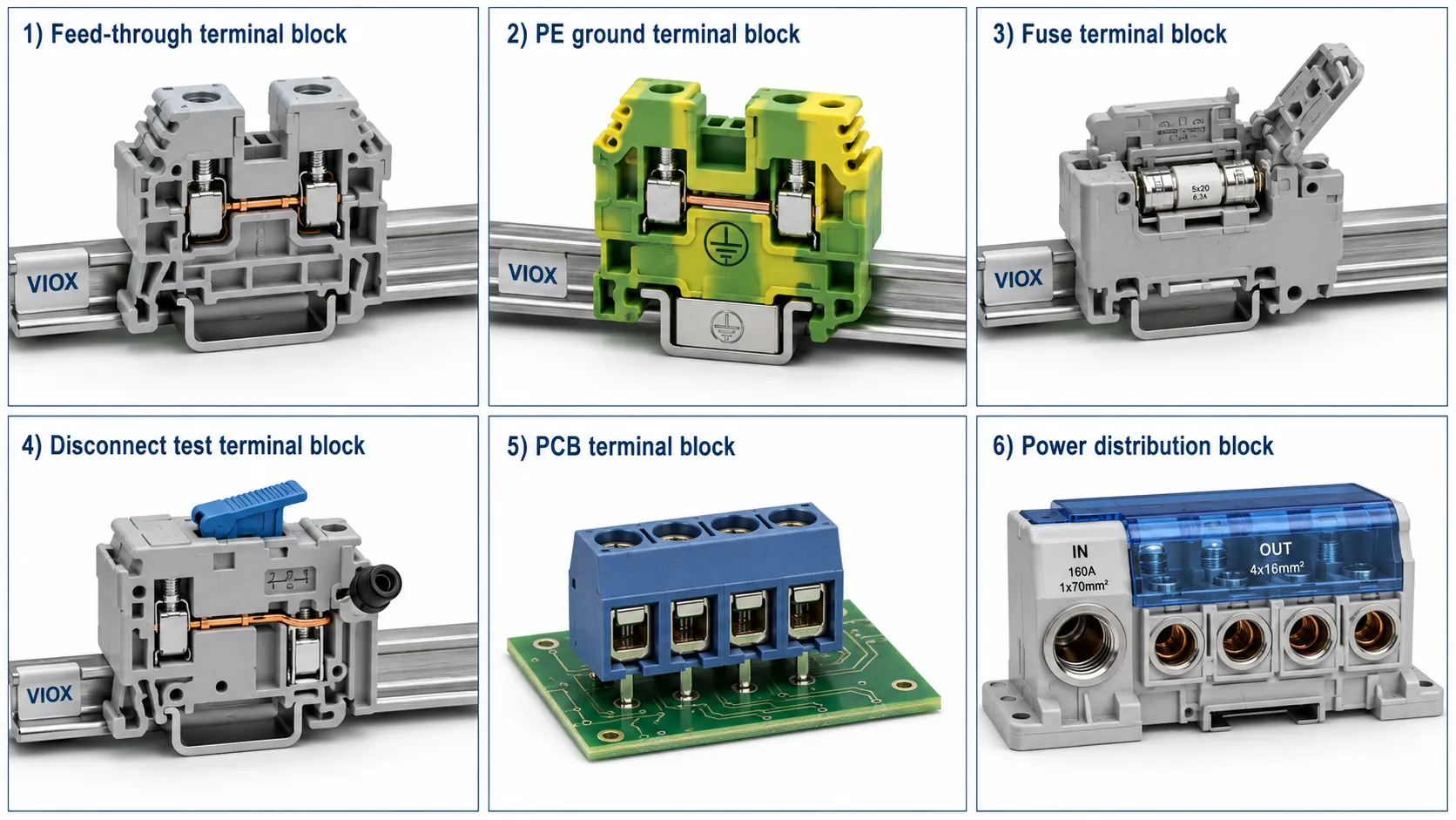
Feed-Through Terminal Blocks
Feed-through terminal blocks connect one conductor on one side to another conductor on the opposite side. They are the most common terminal type in control panels, machinery, and building automation equipment.
Use them for:
- Field wiring to internal control wiring
- Signal and sensor circuits
- Control voltage distribution
- Standard marshalling terminals
- General wire-to-wire connection points
They are simple, compact, and easy to label. The main selection points are conductor size, current rating, voltage rating, terminal width, jumper compatibility, and marking system.
Ground and Protective Earth Terminal Blocks
Ground terminal blocks connect protective conductors to the DIN rail or grounding system. In IEC terminology, protective conductor terminal blocks are covered separately from standard feed-through blocks, commonly under IEC 60947-7-2.
Use them when:
- Equipment grounding conductors must be bonded to the panel ground
- PE circuits need clear identification
- Ground continuity must be mechanically reliable
- Green/yellow protective conductor identification is required
Do not treat a normal feed-through terminal as a protective earth terminal unless the product is designed and marked for that function.
Fuse Terminal Blocks
Fuse terminal blocks integrate a fuse holder into the terminal body. They are often used for control circuits, signal protection, small power circuits, and branch protection inside control panels.
Check:
- Fuse format and fuse rating
- Terminal block current and voltage rating
- Heat dissipation when multiple fuse terminals are installed side by side
- Indicator lamp voltage if a blown-fuse indicator is included
- Replacement access after the panel is wired
Fuse terminal blocks should not be treated as generic feed-through terminals. The fuse, terminal, wiring, and upstream protection must work together.
Disconnect and Test Terminal Blocks
Disconnect, knife-disconnect, and test terminal blocks allow a circuit to be isolated or measured without removing conductors. They are useful in instrumentation, current transformer circuits, signal loops, and commissioning points.
Use them when technicians need to:
- Isolate a signal for testing
- Insert a meter or test plug
- Commission a loop without rewiring
- Separate field wiring from internal circuitry
The selection focus is not only current rating. It also includes test accessory compatibility, safe isolation method, labeling, and maintenance access.
Multi-Level Terminal Blocks
Multi-level terminal blocks stack two or more independent circuits vertically in one terminal body. They are useful when panel space is limited or when related circuits should be grouped together.
Common uses include:
- Sensor wiring with supply, signal, and return
- Compact PLC wiring
- Paired control circuits
- Multi-conductor field cable termination
The risk is serviceability. Dense terminal layouts save rail space, but they must still leave room for wire bending, identification, probing, and replacement.
Barrier Terminal Blocks
Barrier terminal blocks use raised insulation barriers between terminal positions and are commonly mounted directly to panels or equipment bases. They are often used where clear separation, larger screws, and simple service access are more important than modular DIN rail density.
Use them for:
- HVAC equipment
- Equipment junction points
- Legacy panel replacement
- Power wiring where DIN rail is not used
- Applications where visual separation is useful
Barrier blocks are not automatically better for high voltage or high current. Their actual suitability depends on product ratings, spacing, insulation material, termination design, and certification.
PCB Terminal Blocks
PCB terminal blocks connect external wiring to a printed circuit board. They are selected by pitch, current rating, voltage rating, soldering method, conductor range, plug-in design, and board-level mechanical constraints.
Use them for:
- Power supplies
- Control boards
- Sensor interfaces
- I/O modules
- Small automation devices
PCB terminal blocks should not be selected like panel terminal blocks. Board copper thickness, trace width, solder joint stress, creepage, clearance, and mechanical pull forces become part of the design. For PCB spacing decisions, VIOX’s guide to terminal block pitch from 2.54 mm to 10 mm is a useful companion.
Power Distribution Blocks
Power distribution blocks split one incoming conductor into multiple outgoing conductors. They are related to terminal blocks but are not always evaluated or applied the same way.
Use a power distribution block when the design needs:
- One feeder distributed to multiple branches
- Higher-current distribution
- Multiple outgoing conductor sizes
- Clear feeder-to-branch organization
Use terminal blocks when the goal is circuit-by-circuit termination, labeling, marshalling, or modular control wiring. For the difference, see VIOX’s guide to power distribution blocks.
Terminal Block Types by Connection Method
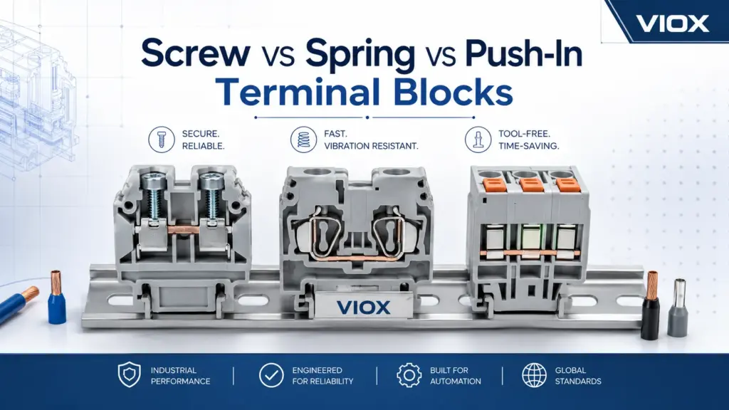
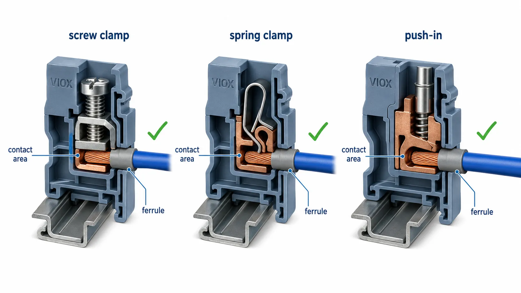
Screw Terminal Blocks
Screw terminal blocks use a screw-driven clamp or pressure plate to secure the conductor. They remain widely used because they are familiar, cost-effective, and suitable for many power and control circuits.
They are a good fit when:
- The installer can apply the specified torque
- The wiring is not frequently changed
- The application needs a robust, visible clamping system
- Larger conductors or power circuits are involved
The key risk is not the screw itself. The risk is incorrect torque, damaged strands, wrong ferrule use, insulation under the clamp, or retightening based on habit rather than the manufacturer’s instruction.
Spring Clamp Terminal Blocks
Spring clamp terminal blocks use spring force to maintain pressure on the conductor. They are often preferred in vibration-prone applications because the spring can maintain stable contact pressure as the conductor settles or experiences thermal cycling.
They are a good fit for:
- Machine tools
- Transportation equipment
- Control cabinets with vibration
- Applications where maintenance access is limited
- Panels where consistent termination quality is important
Spring clamp designs reduce dependence on screw torque, but they still require correct conductor preparation and correct insertion depth.
Push-In Terminal Blocks
Push-in terminal blocks allow solid conductors or ferruled stranded conductors to be inserted directly into the terminal. They are popular in OEM panel production because they reduce wiring time and support high-density cabinet layouts.
They are a good fit for:
- Prefabricated wiring harnesses
- PLC and I/O wiring
- High-volume control panel assembly
- Compact machine wiring
- Repetitive production where wire preparation is standardized
For fine-stranded conductors, ferrules are often required or strongly recommended depending on the terminal design. The datasheet should always be checked before assuming a bare flexible conductor is acceptable.
Stud, Bolt, and High-Current Terminals
Stud or bolt-type terminals are used where larger conductors, lugs, or power connections are required. They are common in power distribution, grounding, battery systems, and higher-current equipment connections.
Check:
- Stud size and lug hole compatibility
- Lug material and plating
- Required tightening torque from the manufacturer
- Insulating cover or touch-protection requirement
- Clearance around the connection after wiring
IDC Terminal Blocks
Insulation displacement connection (IDC) terminals pierce the insulation and contact the conductor without conventional stripping. They are mainly used in low-current signal, telecom, or dedicated connector systems.
IDC terminals should not be used for general power wiring unless the product is specifically designed and rated for that purpose.
Connection Method Comparison
| Connection method | Main advantage | Main risk | Best-fit applications |
|---|---|---|---|
| Screw clamp | Familiar, robust, broad conductor range | Depends on correct torque and wire preparation | Power circuits, field wiring, general panels |
| Spring clamp | Stable clamping force under vibration | Requires correct insertion and tool use where applicable | Machinery, transportation, vibration-prone cabinets |
| Push-in | Fast wiring and high density | Often needs ferruled conductors for flexible wires | OEM panels, PLC wiring, prefabricated harnesses |
| Stud/bolt | Strong mechanical power connection | Requires lug and torque compatibility | Power distribution, batteries, grounding, feeders |
| IDC | Very fast low-current termination | Limited conductor and application range | Signal and communication wiring |
For a practical decision: use screw terminals when controlled torque and broad field familiarity matter, spring clamp terminals when vibration and maintenance stability matter, and push-in terminals when high-volume panel wiring speed matters.
Ratings That Matter When Choosing Terminal Blocks
Rated Current
The rated current tells you how much current the terminal block can carry under specified test and installation conditions. It is not a universal guarantee for every panel layout. Ambient temperature, conductor size, grouping, jumpers, enclosure heat, and adjacent heat-producing devices can all affect real performance.
For power circuits, confirm:
- Terminal block current rating
- Conductor size used in the rating test
- Number of adjacent loaded terminals
- Any derating notes in the datasheet
- Whether jumpers or bridges reduce allowable current
- Temperature-rise data where available
If a terminal runs much hotter than similar adjacent terminals under similar load, the problem is often contact resistance, conductor preparation, or local overload rather than the nominal rating alone. VIOX’s guide to terminal block overheating in control panels explains this failure mode in more detail.
Rated Voltage
Voltage rating is tied to insulation design, creepage distance, clearance distance, material tracking resistance, and installation environment. A terminal block that is safe at one voltage in a clean control cabinet may not be appropriate in a polluted, humid, or compact high-voltage environment.
Check:
- Rated insulation voltage
- Rated operating voltage
- Rated impulse withstand voltage
- Creepage and clearance requirements
- Pollution degree
- Overvoltage category
- Adjacent terminal bridging and accessories
Do not select by voltage label alone. In compact panels, spacing and accessories can matter as much as the printed voltage rating.
Rated Impulse Withstand Voltage
Rated impulse withstand voltage describes the terminal block’s ability to withstand short transient overvoltages. This matters in panels connected to distribution systems, long cables, inductive loads, or environments where switching surges can occur.
The required impulse withstand level depends on the installation category, system voltage, and applicable standard. For a publishable specification, do not guess this value. Use the terminal block datasheet and the project standard.
Creepage and Clearance
Clearance is the shortest distance through air between conductive parts. It helps prevent arc-over.
Creepage is the shortest distance along the surface of the insulating material between conductive parts. It helps prevent tracking across contaminated or damp surfaces.
Both distances are affected by:
- Working voltage
- Impulse voltage
- Pollution degree
- Material group or Comparative Tracking Index (CTI)
- Altitude where relevant
- Accessories such as jumpers, covers, and separators
A compact terminal block may have adequate spacing for one environment but not another. That is why pollution degree and installation environment matter.
Pollution Degree
Pollution degree describes how contamination affects insulation performance. The concept is used in IEC insulation coordination and is important when evaluating creepage and clearance.
| Pollution degree | Typical condition | Practical interpretation |
|---|---|---|
| PD1 | No pollution or only dry, non-conductive pollution | Clean, sealed electronics |
| PD2 | Non-conductive pollution; temporary condensation may occur | Typical indoor control panels |
| PD3 | Conductive pollution or pollution that becomes conductive with condensation | Industrial, outdoor enclosure, marine, dusty or humid environments |
| PD4 | Persistent conductive pollution | Open or severe environments; usually requires special design |
Most control panel applications are not laboratory-clean. If a panel is exposed to condensation, dust, salt mist, or conductive process contamination, terminal block spacing and material selection need more attention than in a clean indoor enclosure.
Wire Size Range
Terminal block wire size is usually given as a conductor cross-section range in mm² and/or AWG. The listed range may differ for solid, stranded, fine-stranded, and ferruled conductors.
Check:
- Minimum and maximum conductor cross-section
- Solid vs stranded conductor approval
- Fine-stranded conductor compatibility
- Ferrule size and insulation collar fit
- Number of conductors allowed per clamping point
- Strip length requirement
- Insulation diameter
Never assume two conductors can be inserted into one terminal because they physically fit. Many terminal blocks are rated for one conductor per clamping point unless the datasheet explicitly allows multiple conductors.
Torque for Screw Terminals
For screw terminals, torque is a manufacturer-specific instruction, not a universal value. Under-torque can create high contact resistance. Over-torque can damage the screw, clamp, conductor, or plastic housing.
Field note: one of the most misleading terminal failures is a connection that looks tight but has actually clamped insulation, damaged strands, or a poorly seated ferrule. The panel may pass a quick visual inspection, but the connection heats under load and becomes intermittent after thermal cycling.
Use a calibrated torque screwdriver where required, and follow the terminal block datasheet rather than applying a generic torque value.
Temperature Rise
Temperature rise is the difference between the terminal’s operating temperature and ambient temperature under load. It is influenced by terminal design, conductor size, contact resistance, enclosure ventilation, grouping, and jumpers.
When selecting terminal blocks for dense panels:
- Avoid placing high-current terminals directly beside heat-sensitive control electronics.
- Check whether jumpers carry the same current as the terminal.
- Keep wire ducts and covers from trapping heat around high-load terminals.
- Compare equivalent terminals under similar load during commissioning when thermal inspection is practical.
- Apply manufacturer derating curves instead of relying on a fixed safety margin.
Short-Circuit and Panel SCCR Context
Terminal blocks used in industrial control panels may also be part of a panel’s Short-Circuit Current Rating (SCCR) evaluation. In North American panel contexts, the SCCR of the panel can be limited by power circuit components, including terminal blocks and power distribution blocks, depending on the construction and listing method.
This does not mean every control terminal needs a high SCCR marking. It means power circuit components must be reviewed as part of the panel design. For the broader concept, see VIOX’s guide to SCCR calculation and panel labeling.
Wire Size and Conductor Compatibility
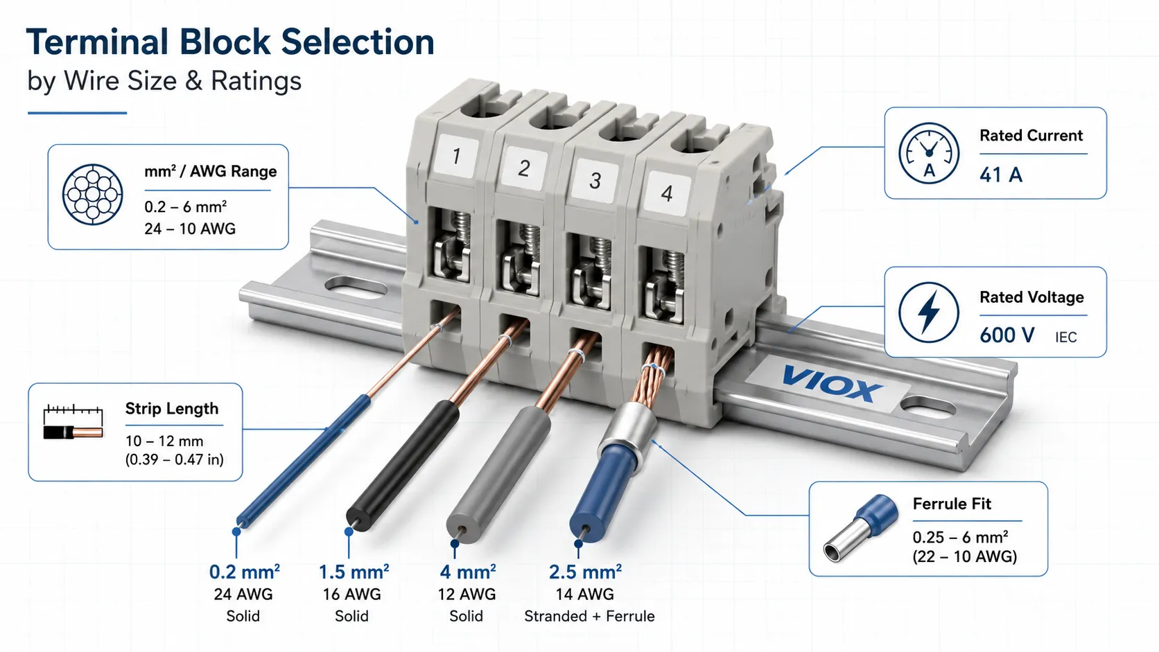
Terminal block selection should start from the conductor, not from the terminal catalog page. The conductor material, strand class, cross-section, insulation diameter, ferrule, and bending space determine whether the connection can be made correctly.
| Wiring detail | What to verify |
|---|---|
| Conductor cross-section | The terminal accepts the actual mm²/AWG size |
| Conductor type | Solid, stranded, fine-stranded, flexible, or ferruled |
| Ferrule fit | Ferrule barrel and plastic collar fit the terminal opening |
| Strip length | Matches datasheet requirement |
| Insulation diameter | Does not prevent full conductor insertion |
| Number of wires | One or multiple conductors only if allowed |
| Copper or aluminum | Use only if the terminal is rated for the conductor material |
| Wire bend radius | Enough panel space remains after wiring |
AWG and mm² Are Not Exact Equivalents
AWG and metric conductor sizes do not convert into neat round numbers. A terminal listed for one metric size should not automatically be assumed to accept the nearest AWG size, and the reverse is also true. The practical issue is not only copper cross-section but also conductor diameter, strand construction, insulation diameter, ferrule shape, and clamping geometry.
When a project uses mixed IEC and North American documentation, verify:
- The actual conductor cross-section
- The terminal’s listed AWG and mm² range
- Whether the terminal accepts ferruled conductors in that size
- Whether the project code or panel standard controls the final conductor sizing
Solid, Stranded, and Fine-Stranded Conductors
Solid conductors, stranded conductors, and fine-stranded flexible conductors behave differently in a terminal. The same nominal cross-section can have different mechanical behavior and insertion characteristics.
For fine-stranded conductors:
- Use ferrules where required or recommended by the terminal manufacturer.
- Confirm the ferrule barrel length fits the clamping zone.
- Confirm the insulated ferrule collar does not block full insertion.
- Use a suitable crimping tool and die.
Ferrules do not automatically make any wire acceptable. The terminal must be rated for ferruled conductors of that size, and the ferrule must be crimped correctly. Poor ferrule crimping can create the same overheating risk as poor terminal selection.
Copper vs Aluminum Conductors
Most control-panel terminal blocks are designed around copper conductors. Aluminum conductors require terminals specifically rated for aluminum or copper/aluminum use, along with suitable preparation and anti-oxidation practices where required.
Do not land aluminum conductors in a copper-only terminal because the immediate fit looks acceptable. Differences in material behavior, oxide formation, and thermal expansion can create long-term reliability problems.
Terminal Block Materials
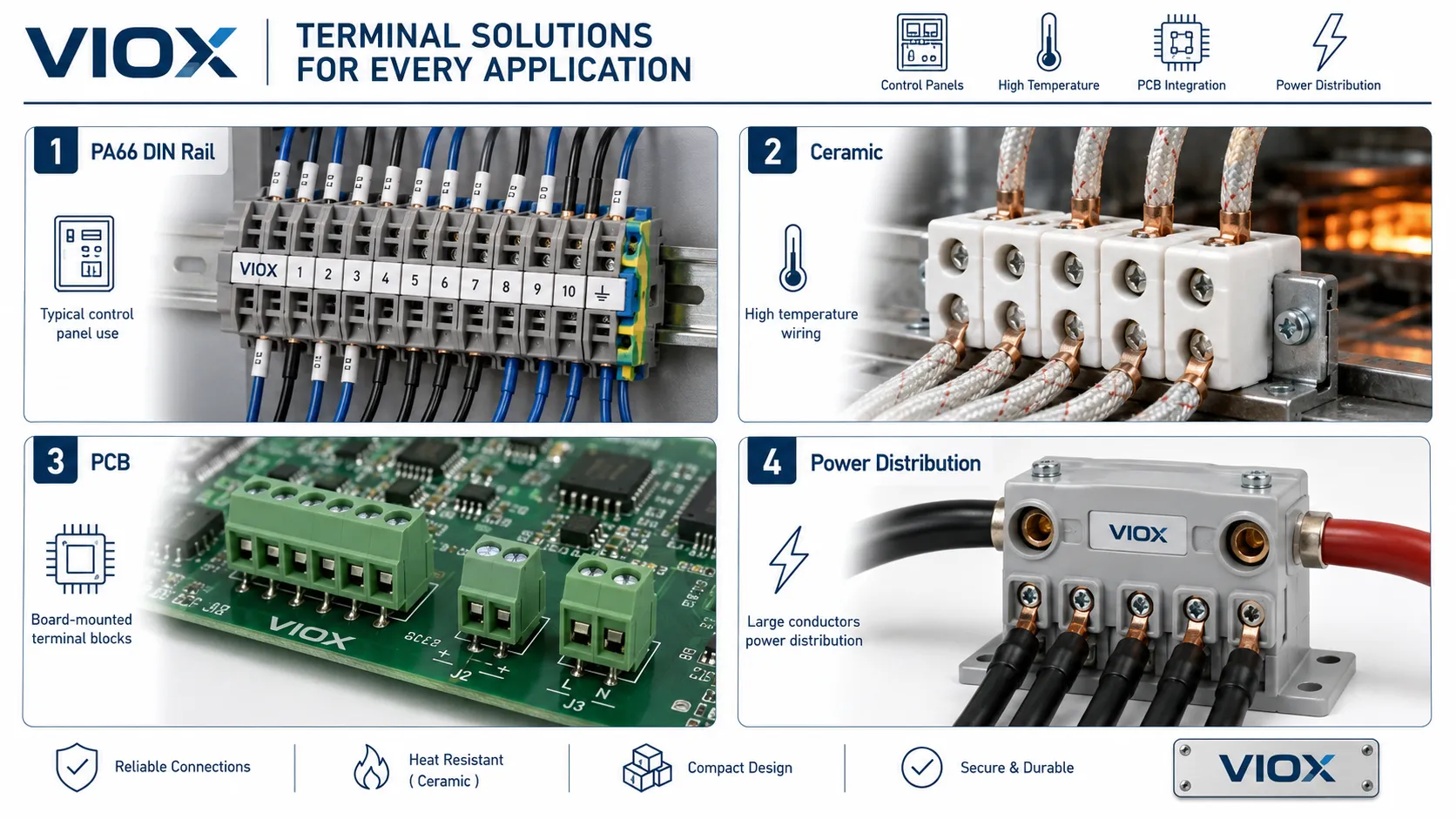
Material selection affects insulation performance, mechanical strength, flame behavior, heat resistance, chemical resistance, dimensional stability, and long-term aging.
Housing Materials
| Material | Typical role | Selection notes |
|---|---|---|
| PA66 / polyamide | Common industrial terminal block housing | Good balance of insulation, toughness, and processability; verify flame rating, CTI, and temperature data |
| PBT | Dimensional stability and electrical insulation | Useful where humidity stability, precision, or tracking resistance is important |
| PC / polycarbonate | Covers, transparent parts, selected housings | Useful where visibility or impact resistance matters; verify heat and chemical exposure |
| Ceramic | High-temperature and heat-resistant terminals | Used where polymer housings may be unsuitable |
| Thermoset materials | High heat and dimensional stability applications | Used in selected power or harsh-environment designs |
PA66 is common in industrial terminal blocks, but the grade matters. Glass filling, flame-retardant system, CTI, moisture behavior, and molding quality can change performance. PBT may be preferred where dimensional stability or moisture behavior is critical. Ceramic is usually reserved for high-temperature environments where polymer housings are not appropriate.
For high-temperature wiring, ceramic terminal blocks should be evaluated separately. VIOX has a dedicated guide on how to select the right ceramic terminal block.
Conductive Parts
The conductive path may use copper alloy, brass, copper, or other conductive materials with appropriate plating. The exact material and surface treatment affect conductivity, corrosion behavior, contact stability, and manufacturability.
| Material or treatment | Why it matters |
|---|---|
| Copper alloy or brass | Common balance of conductivity, mechanical strength, and manufacturability |
| Copper busbar element | Useful where lower resistance and higher current capacity are needed |
| Tin plating | Common surface treatment for oxidation resistance and stable contact behavior |
| Nickel or other plating | May be used where corrosion resistance is important |
| Stainless steel hardware | May be relevant for corrosive or marine environments |
Do not treat shiny metal as proof of performance. Contact geometry, clamping force, plating quality, temperature-rise behavior, and corrosion resistance often matter more than appearance.
What Buyers Should Ask For
For engineering or purchasing evaluation, request:
- Rated current and voltage data
- Conductor range for each conductor type
- Ferrule compatibility information
- Housing material and flame behavior information
- CTI or material group data where relevant
- Temperature-rise data where available
- Certification or test documentation required for the project
- Jumper and accessory current ratings
Standards and Compliance
Terminal block standards depend on product type, market, and installation context. The following standards are commonly encountered, but the exact requirement depends on the project.
| Standard or requirement | Where it is relevant |
|---|---|
| IEC 60947-7-1 | Terminal blocks for copper conductors in low-voltage switchgear and controlgear contexts |
| IEC 60947-7-2 | Protective conductor terminal blocks |
| IEC 60947-7-3 | Fuse terminal blocks where applicable |
| UL 1059 | Terminal blocks in North American product evaluation contexts |
| UL 508A | Industrial control panel construction context in the United States |
| EN 60715 | DIN rail profile dimensions |
| CSA standards | Canadian market requirements |
| ATEX / IECEx | Hazardous or explosive atmosphere applications |
| UL 94 flammability class | Material flammability reference for plastic components |
The important point is not to list as many standards as possible. The important point is to match the terminal block to the actual panel, machine, market, and inspection requirement. A terminal block can be technically well-made but still unsuitable if it lacks the documentation required by the project.
For common approval mistakes, see VIOX’s guide to terminal block certifications and selection mistakes.
Matching Terminal Blocks to Applications
Industrial Control Panels
Industrial control panels usually need DIN rail terminal blocks, clear marking, jumper compatibility, separation between power and control circuits, and reliable field wiring access.
Best fit:
- Feed-through terminals for field wiring
- PE terminals for grounding
- Fuse and disconnect terminals for control circuits
- Spring or push-in terminals for dense OEM panels
- Screw or power terminals where higher current and installer familiarity matter
Machine Wiring
Machine wiring often sees vibration, thermal cycling, and maintenance access constraints. Spring clamp or push-in technology may reduce wiring variability, while screw terminals may still be suitable when torque control is maintained.
The terminal selection should align with the machine’s service conditions, not only the workshop wiring preference.
HVAC and Building Equipment
HVAC equipment may use barrier blocks, DIN rail terminals, PCB terminals, or power distribution blocks depending on the equipment design.
Check:
- Control voltage and power voltage separation
- Compressor and fan circuit current
- Field-service accessibility
- Marking clarity
- Heat inside the enclosure
PLC, Sensor, and Signal Circuits
Signal circuits prioritize density, labeling, shielding, and serviceability. Multi-level terminals, sensor terminals, disconnect terminals, and test terminals can reduce cabinet space and simplify troubleshooting.
For analog signals and low-level circuits, keep routing, shielding, grounding, and separation from noisy power circuits in mind.
Renewable Energy and DC Systems
Solar combiner boxes, battery systems, and DC control equipment may require terminal blocks with suitable DC voltage rating, insulation spacing, material behavior, and environmental resistance. DC systems also need extra attention to polarity, insulation coordination, heat, and maintenance access.
Do not assume an AC-rated terminal arrangement is automatically suitable for a higher-voltage DC assembly. Check the terminal block datasheet and the complete enclosure design.
Marine, Transportation, and Harsh Environments
Marine and transportation applications often combine vibration, corrosion, humidity, temperature cycling, and strict documentation requirements. Spring clamp terminals, corrosion-resistant surface treatments, and appropriate enclosure design may be more important than the lowest component cost.
For marine-specific connection issues, see VIOX’s guide to marine terminal block corrosion-resistant connections.
Power Distribution
Power distribution requires larger conductor capacity, proper spacing, thermal performance, and possibly SCCR evaluation. Do not force a small terminal block into a feeder distribution role when a proper distribution block or busbar system is needed.
For architecture-level decisions, the VIOX article on bus bars vs terminal blocks helps clarify the boundary.
High-Temperature Applications
High-temperature applications may require ceramic or specialty terminal blocks. Common examples include heating equipment, ovens, industrial heaters, and environments where polymer housings may age quickly.
The selection should verify conductor insulation temperature, terminal body material, creepage/clearance, and mounting environment together.
Common Terminal Block Selection Mistakes
1. Selecting by Current Rating Alone
A current rating without voltage, wire size, terminal width, temperature-rise conditions, and installation context is incomplete. A terminal block that looks adequate on paper may overheat if the conductor is undersized, the jumper is overloaded, or the panel has poor heat dissipation.
2. Ignoring Creepage, Clearance, and Pollution Degree
A terminal block used in a clean indoor cabinet and a terminal block used in a humid industrial enclosure may need different insulation assumptions. Condensation, dust, salt mist, or conductive pollution can turn a comfortable design margin into a tracking risk.
3. Ignoring Wire Preparation
Many terminal failures begin before the wire is inserted. Poor stripping, cut strands, loose ferrules, over-crimped ferrules, insulation under the clamp, or stray strands can all create failures that appear later as heat or intermittent faults.
4. Using the Wrong Connection Technology
Screw, spring, and push-in terminals are all valid, but they are not interchangeable in every application. A high-vibration machine, a high-density PLC panel, and a simple power junction point may need different connection logic.
5. Treating Ground Terminals Like Normal Terminals
Protective earth terminals have a safety function. They must be selected, installed, and marked as grounding components, not improvised from generic feed-through terminals.
6. Forgetting Jumpers and Accessories
Jumpers, bridges, end covers, separators, markers, test plugs, and end brackets are part of the terminal block system. A terminal may be correct, but the installation can still fail if the jumper current, spacing, or accessory compatibility is wrong.
7. Mixing Product Families Without Checking Fit
Terminal blocks, jumpers, markers, end plates, and bridges are often system-specific. Mixing visually similar parts from different families can create poor mechanical fit, exposed conductive parts, or unreliable bridging.
8. Using PCB Terminal Blocks for Panel-Level Power Distribution
PCB terminal blocks are designed around board-level constraints. They should not be used as substitutes for panel-mounted power terminals or distribution blocks unless the full board and enclosure design supports that duty.
Step-by-Step Terminal Block Selection Method
Step 1: Define the Circuit Duty
Identify whether the circuit is power, control, signal, PE, test, fuse, disconnect, sensor, or distribution. Terminal type follows circuit function.
Step 2: Confirm Electrical Ratings
Check operating voltage, current, impulse withstand voltage, insulation requirements, and short-circuit or SCCR context where relevant.
Step 3: Confirm Conductor Details
Verify conductor size, conductor class, copper or aluminum compatibility, ferrule requirement, strip length, and number of conductors per clamping point.
Step 4: Select the Connection Technology
Match screw, spring, push-in, stud, IDC, or PCB connection to the installation process, vibration level, maintenance plan, and conductor type.
Step 5: Check Materials and Environment
Review heat, humidity, condensation, chemical exposure, UV exposure, corrosion, vibration, and pollution degree.
Step 6: Verify Standards and Documentation
Confirm the datasheet, certification documents, and project requirements. Do not rely on catalog appearance or generic claims.
Step 7: Confirm Accessories and Layout
Check jumpers, markers, end covers, separators, rail end stops, test plugs, wire bend space, and maintenance access.
Terminal Block Selection Checklist
Use this checklist before releasing a panel design or purchasing terminal blocks for production.
| Check item | Pass condition |
|---|---|
| Circuit function | Terminal type matches power, control, PE, fuse, disconnect, test, or signal function |
| Current rating | Rated current is adequate under actual wiring, grouping, and enclosure conditions |
| Voltage rating | Rated voltage and impulse data fit the circuit and environment |
| Creepage/clearance | Spacing matches voltage, pollution degree, and material assumptions |
| Wire size | Terminal accepts the exact conductor size and type |
| Ferrules | Ferrule use matches the terminal datasheet |
| Material | Housing and conductive parts fit heat, vibration, corrosion, and flame requirements |
| Mounting | DIN rail, PCB, panel, or base mounting fits the equipment layout |
| Accessories | Jumpers, end covers, markers, and test accessories are compatible |
| Standards | Required IEC, UL, CSA, or project approvals are verified |
| Maintenance | Terminals can be labeled, tested, inspected, and replaced when needed |
FAQ
How do I choose the right terminal block size?
Choose terminal block size by conductor cross-section, rated current, rated voltage, terminal width, mounting space, and accessory requirements. Do not choose only by wire diameter. The terminal must also match conductor type, ferrule use, insulation spacing, and the panel environment.
What is the most important rating on a terminal block?
The most important rating depends on the circuit. For power circuits, current rating, voltage rating, conductor size, temperature rise, and insulation spacing are critical. For protective earth circuits, grounding function and standard compliance are critical. For PCB terminals, pitch, board layout, and solder-joint limits become important.
Are screw terminal blocks better than spring terminal blocks?
Neither is universally better. Screw terminals are familiar and strong when installed with the correct torque. Spring terminals are strong in vibration-prone applications because they maintain clamping force without screw torque. The better choice depends on current, conductor type, vibration, maintenance, and installation process.
Do stranded wires need ferrules in terminal blocks?
Fine-stranded and flexible wires often benefit from ferrules, and many push-in terminals require ferrules for stranded conductors. The terminal datasheet should be checked because ferrule rules differ by terminal design and conductor class.
Can I put two wires into one terminal block opening?
Only if the terminal block is specifically rated for two conductors in that clamping point. If the datasheet does not allow it, use a proper jumper, distribution terminal, or power distribution block instead.
What material is best for terminal blocks?
There is no single best material. PA66 and similar engineering plastics are common for industrial terminal blocks, PBT may be useful where dimensional stability is important, and ceramic is used for higher-temperature applications. Material choice should match temperature, insulation, flame behavior, mechanical strength, and environmental exposure.
What is the difference between a terminal block and a power distribution block?
A terminal block mainly provides organized conductor termination and circuit connection. A power distribution block is designed to split one incoming power conductor into multiple outgoing conductors. They overlap in appearance but are not always interchangeable in rating, approval, or panel design.
Which standards apply to terminal blocks?
Common references include IEC 60947-7-1 for terminal blocks for copper conductors, IEC 60947-7-2 for protective conductor terminal blocks, IEC 60947-7-3 for fuse terminal blocks where applicable, and UL 1059 in North American contexts. Industrial panels may also need to consider panel-level requirements such as UL 508A.
Conclusion
A terminal block should be selected as part of the electrical system, not as a small accessory chosen at the end of the project. The right choice depends on circuit function, connection method, current, voltage, wire size, conductor type, insulation spacing, material, mounting method, standards, and maintenance needs.
For VIOX customers, the safest practical approach is to define the wiring duty first, then verify ratings and documentation, and only then compare installation speed, cost, and accessories. That order prevents the most common terminal block problems: overheated connections, poor wire retention, failed inspections, and messy panel maintenance.