What Is a Ring Main Unit (RMU)?
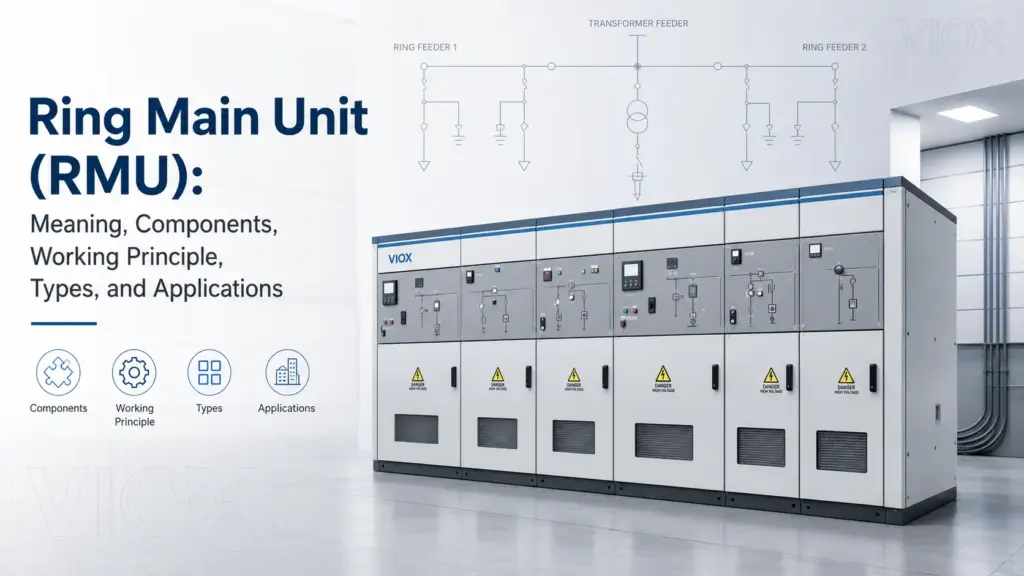
A ring main unit (RMU) is a factory-assembled, metal-enclosed medium-voltage switchgear unit used in ring-type power distribution networks. It normally includes two ring feeder switching units and one transformer feeder protected by a fuse-switch or circuit breaker. The RMU allows operators to connect, isolate, protect, and earth medium-voltage feeders while maintaining supply through an alternative path when the network is designed as a ring.
In simple terms, an RMU is the medium-voltage switching point between the utility distribution network and a distribution transformer, industrial substation, commercial building, solar farm, or infrastructure load.
RMUs are most commonly used in secondary medium-voltage distribution, often in systems such as 11 kV, 12 kV, 24 kV, and 33 kV networks, depending on the country and project specification. The exact voltage, current, short-circuit rating, insulation type, and protection arrangement must always be checked against the manufacturer datasheet and the applicable project standard.
RMU Meaning at a Glance
| Question | Short Answer |
|---|---|
| What does RMU stand for? | Ring Main Unit |
| What is an RMU in electrical systems? | A compact medium-voltage switchgear unit used in ring distribution networks |
| What is the main purpose of an RMU? | To switch feeders, protect transformer circuits, isolate faults, and provide safe earthing |
| Where is an RMU installed? | Distribution substations, transformer stations, industrial plants, commercial buildings, utilities, solar farms, and infrastructure projects |
| Is an RMU low-voltage or medium-voltage equipment? | RMUs are normally medium-voltage switchgear, not low-voltage distribution boards |
| Does an RMU always restore power automatically? | No. Restoration can be manual, remote-controlled, or automated depending on the RMU and network system |
Why Ring Main Units Are Used in Medium-Voltage Distribution
The main value of a ring main unit is network continuity with safe fault isolation.
In a radial network, a feeder fault can interrupt all downstream loads until the fault is repaired or manually bypassed. In a ring network, power can be supplied from more than one direction. The RMU gives operators switching points to isolate the faulty section and restore the healthy part of the network from the opposite side of the ring.
This does not mean every RMU automatically reroutes power by itself. In many installations, field operators must identify the faulted cable section, operate the switches in the correct order, and re-energize the healthy side. In more advanced systems, motorized RMUs, fault passage indicators, relays, and supervisory control and data acquisition (SCADA) can support remote or automated restoration.
RMUs are widely used because they combine several functions in one compact enclosure:
- Ring feeder switching
- Transformer feeder protection
- Cable isolation
- Earthing for maintenance
- Fault section isolation
- Optional metering, protection relay, and remote monitoring
Closed-Loop Topology, Open-Point Operation
One of the most common misunderstandings about ring main units is the word ring.
In many medium-voltage distribution networks, the cable route is physically arranged as a ring, but the system is not always operated as a fully closed parallel loop. A common operating method is closed-loop topology with one normal open point.
That means:
- The cable network is physically capable of being supplied from more than one direction.
- One switch or feeder point is normally kept open.
- The open point prevents uncontrolled parallel operation between sources.
- If a cable section fails, operators isolate the faulty section and may move the open point to restore healthy loads from the opposite side.
This operating logic matters because it affects fault current, protection coordination, switching sequence, and restoration planning. When reading an RMU diagram, do not only ask where the ring is. Ask where the normal open point is.
| Operating Concept | Meaning | Why It Matters |
|---|---|---|
| Physical ring | Cables form a loop between RMUs or substations | Allows alternative supply paths |
| Normal open point | One switching point is kept open during normal operation | Controls fault current and avoids unintended parallel operation |
| Fault isolation | Switches on both sides of the faulty section are opened | Keeps the damaged cable isolated |
| Supply restoration | Healthy sections are re-fed from the opposite side where permitted | Reduces outage area and improves continuity |
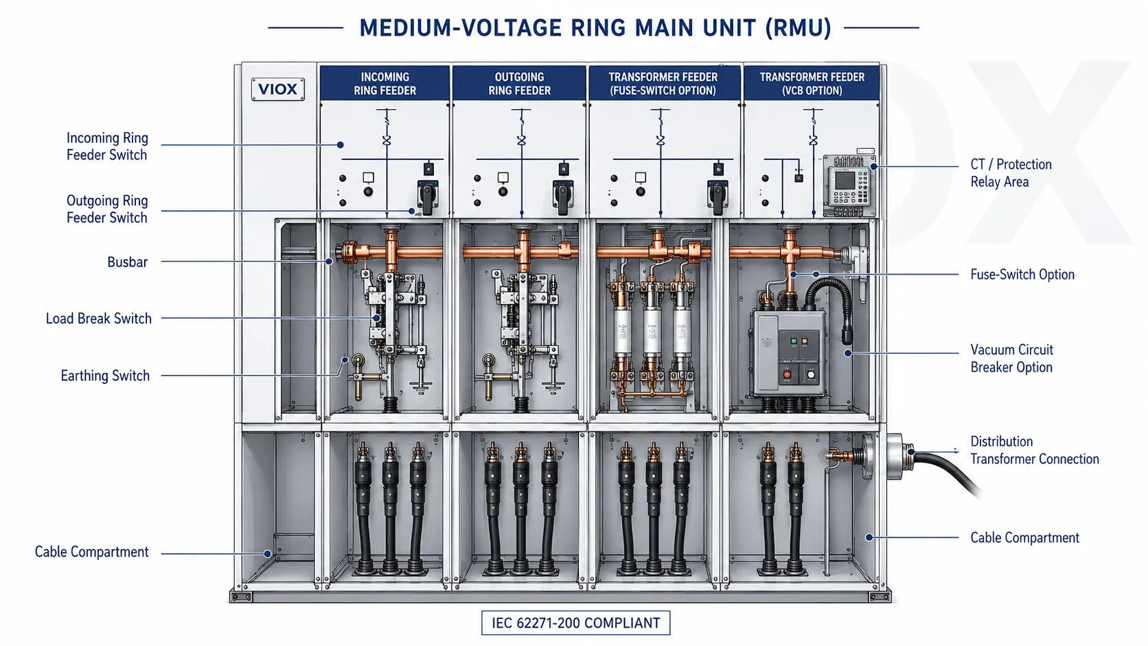
Main Components of a Ring Main Unit
An RMU is not just one switch. It is a coordinated assembly of switching, protection, insulation, control, and safety components.
| Component | Main Function | Engineering Note |
|---|---|---|
| Load break switch (LBS) | Makes and breaks normal load current on ring feeders | Used for normal switching, not for interrupting high short-circuit fault current unless rated for that duty |
| Fuse-switch unit | Protects transformer feeders using high-voltage fuses | Common for distribution transformer protection where fuse coordination is suitable |
| Vacuum circuit breaker (VCB) | Interrupts load current and fault current when combined with protection relay | Used where resettable protection, relay control, or higher protection flexibility is needed |
| Busbar | Connects RMU functional units internally | Must match rated current, insulation level, and short-time withstand requirements |
| Earthing switch | Grounds isolated cables or transformer feeders for maintenance safety | Must be mechanically interlocked to prevent unsafe switching sequences |
| Cable compartment | Provides termination points for incoming, outgoing, and transformer cables | Cable size, termination type, and test access matter during selection |
| Protection relay | Detects overcurrent, earth fault, or other abnormal conditions | Common in circuit breaker RMUs and automated distribution systems |
| CTs and VTs | Provide current and voltage signals for protection and metering | Required when measurement, protection relay input, or remote monitoring is needed |
| Operating mechanism | Enables manual, motorized, or remote switching | Choice depends on utility operation model and automation requirement |
| Insulation system | Provides dielectric separation between live parts and enclosure | Can be SF6 gas, air, solid insulation, or hybrid designs depending on RMU type |
Three-Position Switch: Service, Isolation, and Earth
Many compact RMUs use a three-position switch arrangement to reduce size and improve switching discipline. The exact mechanism depends on the manufacturer, but the functional positions are usually:
| Position | Function | Practical Meaning |
|---|---|---|
| Service / closed | Circuit is connected for normal operation | Feeder or transformer circuit can be energized |
| Isolated / open | Circuit is disconnected | Creates an isolation state before earthing or maintenance |
| Earth | Circuit side is connected to earth | Provides a safer condition for cable testing or maintenance after proper verification |
The three-position design helps prevent unsafe combinations, but it does not replace operating procedure. Before maintenance, technicians still need approved isolation, absence-of-voltage verification, earthing, locking, tagging, and site-specific safety rules.
Ring Main Unit Working Principle
The working principle of an RMU is based on ring network switching and sectionalizing.
A typical RMU has two ring feeder units and one transformer feeder unit:
- One ring feeder receives power from one side of the medium-voltage ring.
- The other ring feeder connects to the next RMU or network section.
- The transformer feeder supplies a distribution transformer through a fuse-switch or circuit breaker.
Under normal operation, one or both ring feeders may be energized depending on the network design and operating scheme. The transformer feeder supplies the transformer, which steps medium voltage down to low voltage for final distribution.
When a fault occurs on one cable section, operators isolate that cable section by opening the relevant ring switches. The healthy sections can then remain energized or be restored from the opposite side of the ring, depending on system design and operating rules.
RMU Working Sequence in Normal and Fault Conditions
| Operating Condition | What the RMU Does | Main Device Involved |
|---|---|---|
| Normal feeder operation | Carries medium-voltage supply through the ring network | Load break switch and busbar |
| Transformer supply | Feeds the distribution transformer from the MV side | Fuse-switch unit or circuit breaker feeder |
| Cable section fault | Isolates the faulty section from the healthy ring | Ring feeder load break switches |
| Transformer fault | Disconnects the transformer feeder from the RMU | HV fuse or circuit breaker with relay |
| Maintenance work | Provides isolation and earthing before access | Disconnector function and earthing switch |
| Supply restoration | Allows the healthy part of the ring to be re-fed from another side | Manual switch, motorized switch, or automated control system |
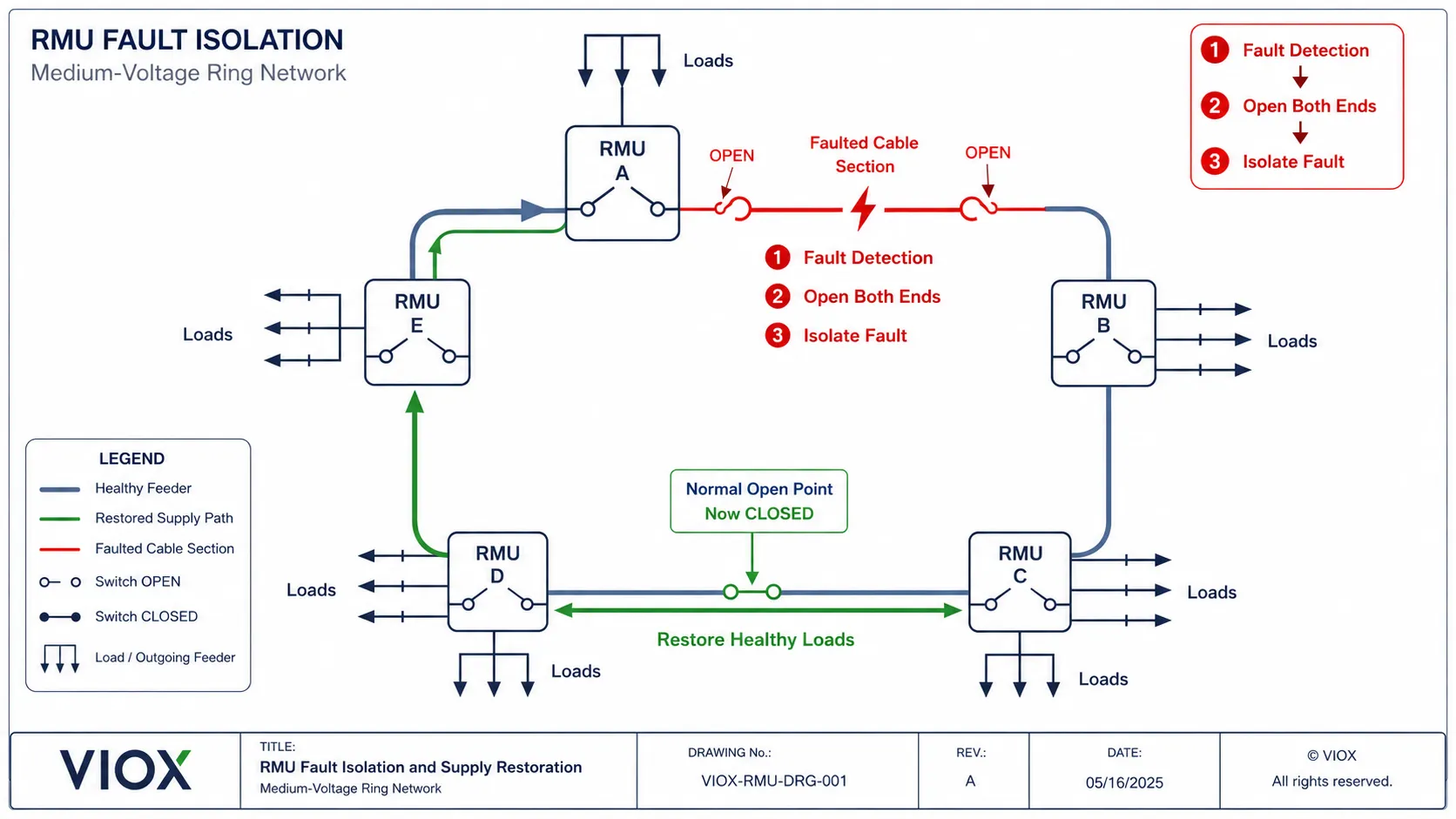
Fault Restoration Logic: What Actually Happens During a Cable Fault
In a real ring network, a cable fault is not solved by simply “letting power flow the other way.” The operator or automation system must identify, isolate, and then restore.
The sequence normally looks like this:
- A fault occurs on one cable section.
- Protection or a fault passage indicator helps identify the affected section.
- The two switching points on both sides of the faulted cable are opened.
- The faulted section remains isolated.
- The normal open point may be closed after checks, so healthy loads can be supplied from the alternate side.
- The damaged cable is repaired and the network is returned to its intended operating state.
| Step | Field Question | RMU Action |
|---|---|---|
| Identify | Which cable section is faulted? | Use relay indication, fault passage indicator, SCADA event, or site testing |
| Isolate | Which two switches bound the fault? | Open both ends of the faulted section |
| Earth | Is the isolated section safe for work? | Apply earthing switch after approved verification |
| Restore | Which healthy loads can be re-fed? | Close the appropriate open point only after switching checks |
| Normalize | How is the network returned after repair? | Restore the original switching plan or updated operating plan |
This is why a correct RMU single line diagram and cable labeling are not paperwork details. They directly affect restoration speed and operator safety.
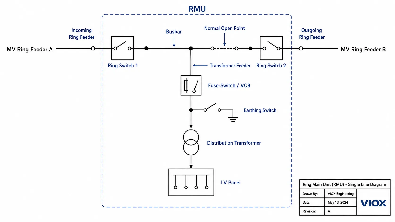
Ring Main Unit Diagram: How Power Flows in a Ring Network
A useful ring main unit diagram should be drawn as a single line diagram (SLD), not as a decorative cabinet picture. For most secondary distribution RMUs, the diagram should show the medium-voltage ring feeders, the busbar, the transformer feeder, the switching devices, the earthing switches, and the protection device used on the transformer feeder.
A basic RMU SLD normally shows three functional sections:
- Incoming ring feeder
- Outgoing ring feeder
- Transformer feeder
The two ring feeders connect the RMU into the medium-voltage ring. The transformer feeder connects the RMU to a distribution transformer.
In a technical drawing, this is often described as a CCF, CCC, or CCV style configuration, depending on the manufacturer naming convention:
| Common Configuration | Meaning in Practice | Typical Use |
|---|---|---|
| CCF | Two cable switch units plus one fuse-switch transformer feeder | Standard distribution transformer protection |
| CCV | Two cable switch units plus one vacuum circuit breaker transformer feeder | Larger transformer feeders or relay-based protection |
| CCC | Three cable switch units | Ring sectionalizing without a transformer feeder |
The exact letters are not universal across all manufacturers, but the engineering idea is the same: two ring cable feeders plus one outgoing feeder is the most recognizable RMU topology.
If a cable fault occurs between two RMUs, the two RMUs on either side of the fault can isolate that cable section. The remaining network can then be supplied through the healthy side of the ring.
For publication, this section should use a proper SLD-style diagram showing:
- Incoming feeder
- Outgoing feeder
- Busbar
- Load break switches
- Transformer feeder
- Fuse-switch or circuit breaker
- Earthing switch
- Distribution transformer
- Faulted cable section
- Healthy supply path
Engineer note: In an RMU SLD, do not show the load break switch as if it can interrupt transformer short-circuit fault current by itself. In a fuse-switch feeder, the fuse clears the fault. In a VCB feeder, the circuit breaker clears the fault under relay command.
RMU in Transformer Distribution: What Does It Do?
Many users search for RMU in transformer because RMUs are commonly installed on the medium-voltage side of distribution transformers.
The RMU is not part of the transformer itself. It is the medium-voltage switching and protection equipment feeding the transformer.
In a typical secondary substation:
- The RMU receives medium-voltage supply from the utility ring.
- The transformer feeder of the RMU supplies the distribution transformer.
- A fuse-switch or circuit breaker protects the transformer feeder.
- The transformer steps the voltage down to low voltage.
- The low-voltage side feeds a main distribution board or low-voltage switchboard.
For small and medium distribution transformers, a fuse-switch RMU is common because high-voltage fuses can provide fast and economical transformer fault protection. For larger transformers, critical loads, or systems requiring relay-based protection, a circuit breaker RMU may be preferred.
Fuse-Switch RMU vs Circuit Breaker RMU
Not all RMUs protect transformer feeders in the same way. The two common arrangements are fuse-switch RMU and circuit breaker RMU.
| Item | Fuse-Switch RMU | Circuit Breaker RMU |
|---|---|---|
| Main protection device | High-voltage fuse with switch-disconnector | Circuit breaker with protection relay |
| Typical use | Distribution transformer protection | Larger transformers, critical feeders, automated protection |
| Fault clearing | Fuse interrupts fault current | Circuit breaker trips by relay command |
| Reset after fault | Fuse must be replaced | Breaker can be reset after inspection and fault clearance |
| Protection flexibility | Limited by fuse characteristics | Adjustable relay settings, more coordination options |
| Cost and complexity | Usually simpler and more economical | Higher cost but more flexible |
| Best fit | Standard secondary distribution transformer feeders | Industrial, utility, infrastructure, and automation-heavy feeders |
The correct choice depends on transformer rating, fault level, utility practice, protection coordination, maintenance strategy, and project specification.
Expert Tip: Do Not Select Fuse-Switch RMUs Only by Transformer kVA
For small and medium distribution transformers, fuse-switch RMUs are widely used and often economical. But as transformer size increases, the coordination between the high-voltage fuse, transformer inrush current, overload behavior, and upstream protection becomes more sensitive.
In real projects, engineers often review the fuse time-current curve against:
- transformer full-load current
- magnetizing inrush current
- permissible overload behavior
- minimum fault current on the MV side
- upstream protection settings
- manufacturer transfer-current limits for the fuse-switch combination
For larger transformers, critical loads, or networks where nuisance fuse operation would be difficult to recover from, a VCB RMU with a protection relay is often easier to coordinate and maintain. This is especially true where the operator wants adjustable overcurrent and earth-fault protection rather than a fixed fuse characteristic.
Field Reliability: Cable Terminations Are Often the Weak Point
In many RMU fault investigations, the visible cabinet gets blamed first, but the root cause is often outside the sealed switch tank. Medium-voltage cable terminations and separable connectors are frequent weak points because they depend heavily on installation quality.
Common field issues include:
- poor cable preparation
- moisture ingress into cable accessories
- incorrect stress control installation
- loose or contaminated separable connectors
- damaged cable screen bonding
- condensation inside the cable compartment
- unclear cable tags after later site modifications
For this reason, RMU inspection should not stop at the front panel indicator. A practical site review should include the cable compartment, cable accessory condition, earthing continuity, heater operation, and signs of tracking, partial discharge, overheating, or moisture.
Technician tip: If an RMU feeder has repeated fault indications but the switch tank, relay, and mechanism appear normal, inspect the cable head and termination workmanship before assuming the RMU body is defective.
Automation Reality Check: DTU, PT, Battery, and SCADA
A motorized RMU is not automatically a reliable automated RMU. Remote operation depends on the entire auxiliary system.
Automation reliability usually depends on:
- motorized operating mechanisms
- distribution terminal unit (DTU) or remote terminal unit (RTU)
- protection relay and fault indication logic
- voltage transformer (VT/PT) or auxiliary supply arrangement
- DC battery and charger health
- communication gateway and protocol integration
- correct point mapping in SCADA
- tested local/remote operating procedures
In the field, automation failures are often caused by weak auxiliary power, dead batteries, communication problems, incorrect status mapping, or untested remote-control logic. The RMU may be mechanically capable of remote switching, but the distribution automation chain still fails if the support circuits are not maintained.
| Automation Element | What to Verify |
|---|---|
| Motorized mechanism | Local and remote operation, position feedback, operating time |
| DTU/RTU | Communication status, event records, correct signal mapping |
| PT/VT supply | Voltage output, fuse condition, auxiliary supply logic |
| Battery and charger | Backup duration, charger alarm, DC voltage health |
| SCADA integration | Command confirmation, status feedback, naming consistency |
| Cyber/operation controls | Authorization, interlocks, remote/local mode discipline |
Types of Ring Main Units
RMUs can be classified by insulation medium, switching device, installation environment, and automation level.
SF6 Gas-Insulated RMU
SF6 gas-insulated RMUs use sulfur hexafluoride gas as the insulation medium. They are compact and widely used in medium-voltage distribution. However, SF6 has a very high global warming potential, so many utilities and manufacturers are moving toward reduced-SF6 or SF6-free alternatives where project requirements allow.
Air-Insulated RMU
Air-insulated RMUs use air as the primary insulation medium. They are easier to understand and maintain, but generally require more space than gas-insulated designs.
Solid-Insulated RMU
Solid-insulated RMUs use epoxy resin or other solid insulation systems around live parts. They are often selected where environmental considerations, sealed construction, or reduced gas handling are priorities.
Vacuum RMU
Vacuum technology is commonly used for circuit breaker interruption inside RMUs. Vacuum interrupters provide effective arc extinction for medium-voltage switching and fault interruption when used in properly rated circuit breaker units.
Manual, Motorized, and Automated RMU
RMUs may be operated manually, motorized for remote operation, or integrated into automated distribution systems. A basic manual RMU is suitable for many secondary substations, while motorized or automated RMUs are used where utilities need faster fault location, isolation, and service restoration.
Ring Main Unit Applications
Ring main units are used wherever medium-voltage distribution requires compact switching, transformer protection, and feeder sectionalizing.
Utility Secondary Distribution
Utilities use RMUs in urban and suburban distribution networks to connect distribution transformers and sectionalize ring feeders. This is one of the most common RMU applications.
Distribution Transformer Stations
An RMU is often installed next to or inside a transformer substation. It provides the medium-voltage incoming and outgoing feeder switching, plus transformer feeder protection.
Commercial Buildings and High-Rise Projects
Large buildings, shopping centers, hospitals, hotels, and office complexes often require medium-voltage incoming supply. RMUs help manage incoming feeders and transformer protection in compact electrical rooms.
Industrial Facilities
Factories and process plants use RMUs for medium-voltage distribution between substations, transformer feeders, and internal MV network sections.
Renewable Energy and Microgrids
Solar farms, wind projects, battery energy storage systems, and microgrids may use RMUs on the medium-voltage collection or grid-connection side. In these applications, bidirectional power flow, protection coordination, and utility interconnection requirements must be carefully reviewed.
Infrastructure Projects
Rail systems, airports, water treatment plants, ports, telecom facilities, and public infrastructure often use RMUs because they need compact MV switching with clear isolation and feeder management.
RMU vs Traditional Switchgear
An RMU is a type of medium-voltage switchgear, but it is optimized for ring distribution networks and compact secondary substations.
| Feature | Ring Main Unit | Traditional MV Switchgear |
|---|---|---|
| Typical role | Secondary distribution, ring feeder switching, transformer feeder protection | Primary distribution, larger substations, feeder control, busbar systems |
| Configuration | Compact functional units in one enclosure | More modular and expandable lineup |
| Common feeders | Ring feeder + transformer feeder | Multiple incomers, feeders, bus couplers, metering panels |
| Space requirement | Usually compact | Often larger, depending on configuration |
| Protection options | Fuse-switch or circuit breaker feeder | Circuit breakers, relays, metering, more complex schemes |
| Application | Urban substations, transformer stations, distribution rings | Utility substations, industrial MV switchboards, larger power systems |
An RMU is not a replacement for every medium-voltage switchgear lineup. It is best suited when the project needs compact ring network switching and transformer feeder protection.
Key RMU Specifications to Check
Before selecting an RMU, engineers and procurement teams should check the following items.
| Specification | What to Check | Why It Matters |
|---|---|---|
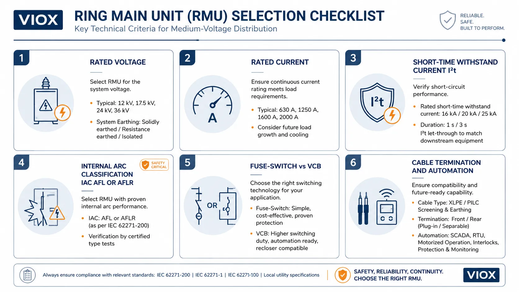
| Rated voltage | System voltage and insulation level | Must match the MV network voltage and overvoltage requirements |
| Rated current | Ring feeder and transformer feeder current | Prevents overheating and ensures continuous operation |
| Short-time withstand current | Network fault level and duration | RMU must withstand fault current until protection clears it |
| Making capacity | Ability to close onto a fault condition | Important for safe switching under abnormal conditions |
| Breaking capability | Load current or fault current interruption rating | Depends on whether the unit uses LBS, fuse-switch, or VCB |
| Insulation medium | SF6, air, solid, vacuum, or hybrid | Affects size, maintenance, environmental impact, and application fit |
| Protection scheme | Fuse protection or relay-controlled breaker | Determines transformer protection and coordination flexibility |
| Cable termination | Cable size, connector type, test access | Critical for installation and maintenance |
| Earthing arrangement | Earthing switch rating and interlocking | Essential for safe maintenance |
| Automation requirement | Manual, motorized, SCADA-ready | Determines remote control and fault restoration capability |
| Standards and approvals | IEC, IEEE, local utility requirements | Must match project and regional acceptance criteria |
Short-Time Withstand Current and Thermal Stress
For RMU procurement, short-time withstand current is one of the most important safety and reliability parameters. It tells you whether the RMU can thermally and mechanically withstand the available fault current until the upstream protection clears the fault.
Common project specifications may reference values such as 16 kA, 20 kA, 21 kA, or 25 kA for 1 second or 3 seconds, depending on the network fault level and utility requirement. These values are examples only; the correct rating must be selected from the actual short-circuit study and project specification.
The underlying engineering principle is thermal energy:
Thermal stress is proportional to I²tWhere:
Iis the fault currenttis the fault duration
That means a higher fault current or a longer clearing time sharply increases the thermal stress on busbars, switches, cable connections, and internal conductors. This is why two RMUs with the same rated voltage may not be interchangeable if their short-time withstand current differs.
Internal Arc Classification: IAC AFL and AFLR
For modern medium-voltage switchgear, internal arc classification (IAC) is a major safety requirement in many tenders. It describes how the switchgear has been tested to protect people if an internal arc fault occurs inside the enclosure.
Common marking logic includes:
| IAC Marking | Meaning |
|---|---|
| A | Accessibility for authorized personnel |
| F | Protection at the front side |
| L | Protection at the lateral sides |
| R | Protection at the rear side |
| AFL | Internal arc classification for front and lateral access |
| AFLR | Internal arc classification for front, lateral, and rear access |
For example, a project may require an RMU with internal arc classification such as IAC AFL 20 kA/1s or IAC AFLR 20 kA/1s, depending on installation layout and operator access. Do not copy these values blindly. The required IAC level depends on local utility rules, room layout, accessibility, expected fault level, and project safety specification.
This is one of the biggest differences between a serious RMU specification and a generic product comparison. If the RMU is installed in a compact indoor substation where operators may stand near the front, side, or rear of the cabinet, IAC direction and duration matter.
RMU Standards and Technical References
RMUs are medium-voltage switchgear assemblies, so they are normally specified under high-voltage switchgear and controlgear standards rather than low-voltage panel standards.
Commonly referenced standards include:
- IEC 62271-200 for AC metal-enclosed switchgear and controlgear above 1 kV and up to 52 kV
- IEC 62271-1 for common specifications for high-voltage switchgear and controlgear
- IEC 62271-100 for high-voltage AC circuit breakers
- IEC 62271-103 for switches above 1 kV
- IEC 62271-102 for AC disconnectors and earthing switches
- IEC 60282-1 for high-voltage fuses
- IEC 61869 for instrument transformers
- IEC 60529 for enclosure ingress protection classification where applicable
Do not assume an RMU is compliant with a standard just because the article or catalogue mentions that standard. For procurement, always verify the exact model, rating, type test report, routine test record, and project-required certification documents.
Common Misunderstandings About Ring Main Units
Misunderstanding 1: An RMU Is the Same as a Low-Voltage Distribution Box
An RMU is normally medium-voltage switchgear. A low-voltage distribution box distributes power after the transformer has stepped voltage down. The construction, insulation, fault level, testing, and safety requirements are completely different.
Misunderstanding 2: Every RMU Automatically Restores Power
An RMU provides the switching points needed for fault isolation and restoration, but the restoration method depends on the system. It may be manual, remote-controlled, or automated.
Misunderstanding 3: A Load Break Switch Can Interrupt Any Fault
A load break switch is designed for normal load switching within its rating. Fault interruption normally requires a fuse or circuit breaker arrangement. This distinction is important when selecting between fuse-switch and VCB RMUs.
Misunderstanding 4: SF6-Free Always Means Better for Every Project
SF6-free or reduced-SF6 designs can be attractive for environmental reasons, but the final decision must also consider footprint, rating, availability, utility approval, maintenance capability, and lifecycle requirements.
Misunderstanding 5: RMU Ratings Are Universal
Two RMUs that both say 12 kV or 24 kV may still differ in rated current, short-time withstand current, internal arc classification, cable termination system, protection arrangement, and automation capability.
How to Choose a Ring Main Unit
For practical selection, start with the network and transformer requirements, not only the enclosure size.
1. Confirm System Voltage and Insulation Level
Match the RMU rated voltage and insulation level to the medium-voltage network. Typical distribution networks vary by region, so the project specification and utility requirement must control the final selection.
2. Check Network Fault Level
The RMU must be suitable for the available short-circuit current at the installation point. Check short-time withstand current, making capacity, and fault interruption capability where applicable.
3. Define Feeder Configuration
A common RMU configuration includes two ring feeders and one transformer feeder. Larger projects may require additional transformer feeders, metering panels, bus section functions, or extension modules.
4. Choose Fuse-Switch or Circuit Breaker Protection
Fuse-switch RMUs are common for transformer feeders. Circuit breaker RMUs are preferred where relay protection, remote tripping, reusability after fault clearance, or more flexible coordination is required.
5. Select Insulation Type
Choose SF6, air-insulated, solid-insulated, or vacuum-based designs according to project requirements, environmental policy, footprint, availability, and maintenance capability.
6. Check Cable and Installation Requirements
Verify cable entry direction, cable termination type, test access, cable compartment clearance, gland plate design, installation environment, and earthing arrangement.
7. Decide Manual or Automated Operation
If the network requires remote switching or faster service restoration, specify motorized mechanisms, communication interfaces, fault indicators, protection relays, and SCADA compatibility.
How to Analyze an RMU Like a Technician
When a technician or engineer walks up to an RMU, the nameplate is only the starting point. The real operating logic is in the one-line diagram, cable routes, switch positions, protection devices, and auxiliary circuits.
Use this field sequence:
| Step | What to Check | Why It Matters |
|---|---|---|
| 1. Identify both sources | Where do the incoming ring feeders come from? | Confirms the real supply paths |
| 2. Locate the normal open point | Which switch is normally open? | Explains how the ring is operated |
| 3. Separate incomers and outgoers | Which feeders pass through and which feed transformers or loads? | Prevents switching the wrong circuit |
| 4. Check protection devices | Fuse-switch, VCB, CT, relay, earth-fault detection | Determines how faults are cleared |
| 5. Trace the fault isolation path | Which two devices isolate a cable fault? | Supports safe and fast restoration |
| 6. Verify auxiliary systems | PT/VT, battery, DTU/RTU, communication | Determines whether automation will work in a real outage |
| 7. Inspect cable terminations | Cable heads, connectors, bonding, moisture, labeling | Finds common failure points outside the switch tank |
This is the difference between recognizing an RMU and understanding it. A cabinet can look correct from the front while the real risk sits in the cable compartment, auxiliary power system, or outdated single line diagram.
FAQ
What is a ring main unit?
A ring main unit is a compact medium-voltage switchgear assembly used in ring distribution networks. It normally includes ring feeder switches and a transformer feeder protected by a fuse-switch or circuit breaker.
What does RMU stand for?
RMU stands for Ring Main Unit.
What is RMU in electrical distribution?
In electrical distribution, an RMU is a medium-voltage switching and protection unit used to connect ring feeders, isolate cable sections, and feed distribution transformers.
What is the working principle of a ring main unit?
An RMU works by connecting medium-voltage feeders in a ring network. If one feeder section fails, the faulty section can be isolated and the healthy part of the network can be supplied from another side of the ring, depending on the network design.
What is RMU in transformer?
An RMU is usually installed on the medium-voltage side of a distribution transformer. It switches and protects the transformer feeder but is not part of the transformer itself.
What are the main components of an RMU?
Main RMU components include load break switches, fuse-switch units or circuit breakers, busbars, earthing switches, cable compartments, operating mechanisms, protection relays, and insulation systems.
What is the difference between RMU and switchgear?
An RMU is a compact type of medium-voltage switchgear designed mainly for ring distribution networks and transformer feeders. Traditional switchgear can be larger, more modular, and used for broader primary and secondary distribution applications.
Is an RMU used in low voltage or medium voltage?
An RMU is normally used in medium-voltage distribution. It should not be confused with low-voltage distribution boards, consumer units, or panelboards.
Does an RMU use SF6 gas?
Many RMUs use SF6 gas insulation, but not all. Air-insulated, solid-insulated, vacuum, and hybrid RMU designs are also available. The correct insulation type depends on project requirements and manufacturer design.
Can an RMU isolate a fault automatically?
Some automated RMUs can support remote or automatic fault isolation when equipped with motorized mechanisms, relays, communication, and distribution automation systems. Basic RMUs may require manual operation.
