On this page
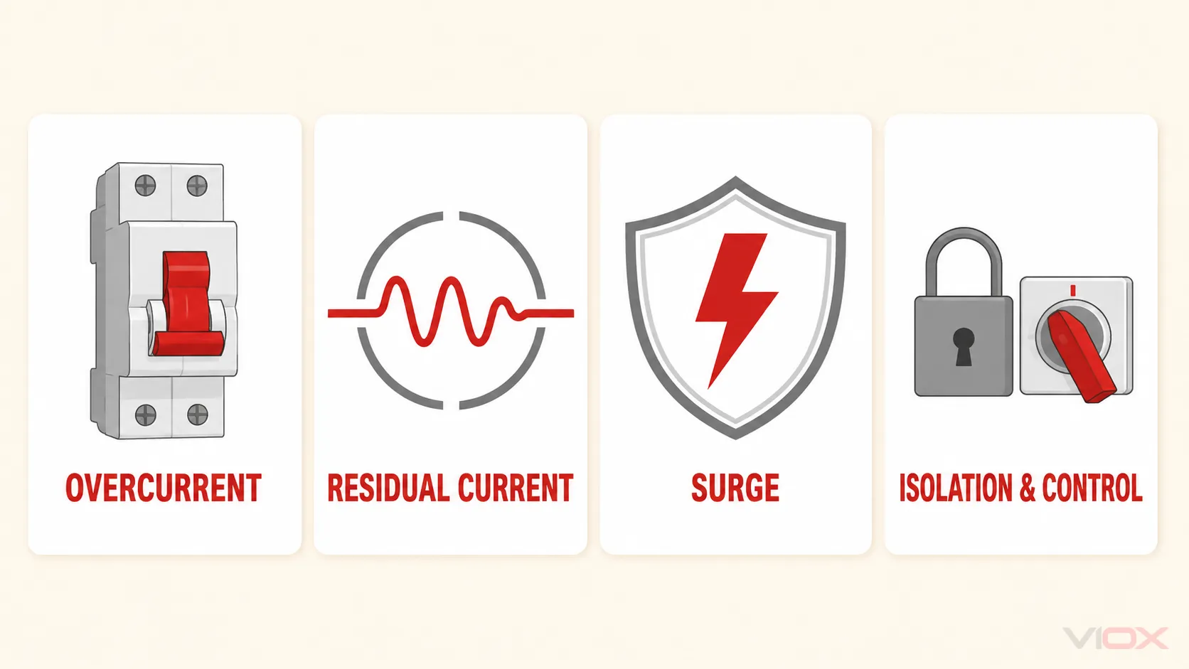
A commercial EV charging site does not need ACBs, MCCBs, RCBOs, RCDs, SPDs, contactors, and isolators stacked in one universal sequence. Each device has a different duty. The architecture should be selected from the supply capacity, diversified charging load, prospective short-circuit current, conductor and installation method, earthing arrangement, required selectivity, EVSE design, surge risk, service-continuity target, and local code.
At a small AC charging site, an existing main switchboard may feed individual charge-point circuits through MCBs or RCBOs. A larger charging hub may justify a dedicated switchboard with an MCCB incomer and coordinated outgoing protection. An ACB becomes relevant only where the service or main distribution duty, frame size, fault level, protection functions, maintainability, and switchboard design justify it. DC fast chargers follow the charger’s certified architecture and manufacturer instructions; they cannot be designed by scaling an AC wallbox circuit.
Protection Architecture at a Glance
| Level | Design question | Devices that may perform the duty | What the device does not prove |
|---|---|---|---|
| Service / main board | How is the site supply switched and protected at the calculated load and fault level? | Existing main breaker, MCCB, or ACB depending on the installation | That an ACB is required merely because charging is commercial |
| Charging distribution board | How is the dedicated board isolated and its busbar/feeder protected? | Switch-disconnector, MCCB, MCB, fuse, metering, control | That one nominal rating is suitable for every site |
| Charger feeder | How are the cable and charger feeder protected against overload and short circuit? | MCCB, MCB, fuse, or manufacturer-specified device | Residual-current protection unless that function is explicitly included |
| Individual AC connection point | How are overcurrent and residual-current duties provided for that outlet/connector? | MCB plus RCD, or RCBO, with the required DC-residual-current solution | That any Type A RCBO alone is suitable for every EVSE |
| Residual DC current | Does the EVSE include compliant DC residual-current detection, or is an external solution required? | Type B RCD, or Type A/F RCD with appropriate RDC-DD, subject to local rules and EVSE instructions | That an RDC-DD replaces the accompanying RCD |
| Transient overvoltage | Where is surge protection required and how are stages coordinated? | Type 1, Type 2, or combined SPD arrangements as determined by the installation | That one SPD beside the charger protects every power/data path |
| Functional switching | How will charging be enabled, shed, remotely stopped, or interlocked? | EVSE controls, contactor, shunt trip, undervoltage release, energy-management system | Short-circuit, overload, or residual-current protection unless separately provided |
| Local isolation | How can equipment be safely isolated for maintenance and emergency procedures? | Lockable switch-disconnector or manufacturer-defined isolating means | Permission to work live or bypass lockout/tagout procedures |
The protective-device manufacturer, EVSE manufacturer, switchboard builder, and designer must agree on the boundaries. A symbol labelled “RCBO” or “MCCB” in a concept drawing does not establish ratings, coordination, or compliance.
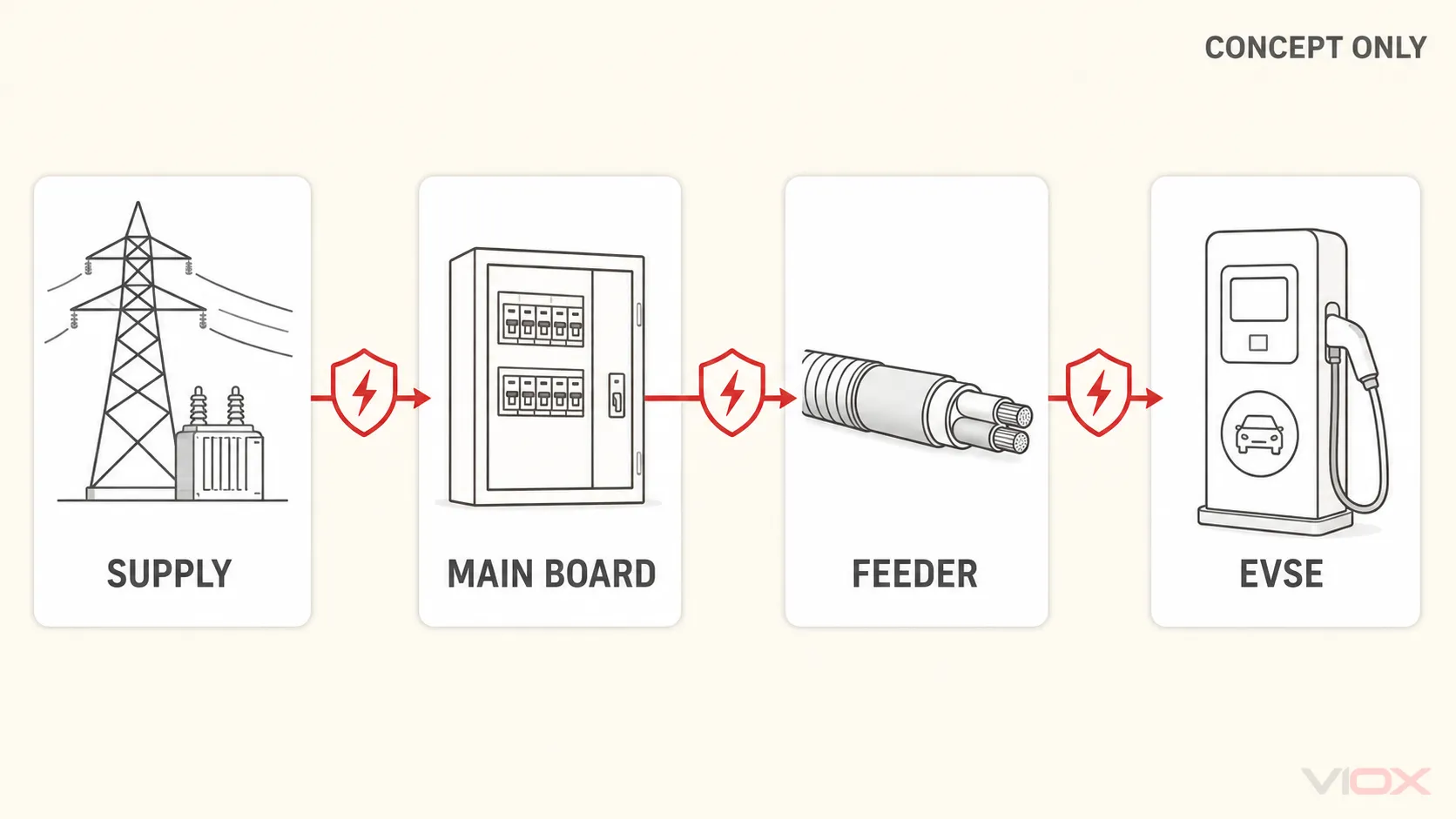
Start With the Inputs, Not the Breaker Frame
Before selecting an ACB, MCCB, MCB, RCBO, RCD, or SPD, collect the following inputs:
- supply voltage, phases, frequency, earthing arrangement, transformer/service rating, and utility constraints;
- existing maximum demand, charging power, charging diversity or load-management strategy, power factor, efficiency, harmonics, and future expansion;
- prospective short-circuit current at the service, charging board, and charge-point terminals;
- feeder length, conductor material and size, installation method, grouping, ambient temperature, allowable voltage drop, and termination limits;
- EVSE topology, number of connectors, maximum current per connection point, incorporated protective functions, manufacturer’s specified upstream device, and certification/listing;
- required uptime, acceptable loss of multiple chargers after one fault, selectivity targets, maintenance access, remote monitoring, and spare strategy;
- lightning exposure, supply type, upstream SPDs, cable routing, data/communications interfaces, and local overvoltage rules;
- applicable installation code, equipment standards, authority requirements, and the editions adopted in the project jurisdiction.
These inputs determine the architecture. The commercial-versus-residential EV protection guide explains why scale, diversity, public access, uptime, and distribution-board structure change the commercial design task.
What Each Protection Device Is For
ACB: main-distribution duty, not a commercial-site default
An air circuit breaker can be appropriate at a high-current main switchboard where its rated operational voltage/current, breaking capacity, making capacity, short-time withstand, trip-unit functions, selectivity settings, communications, and maintainability fit the calculated duty. It may serve as a service or major distribution incomer in a large installation.
An ACB is not automatically required by charger count, the word “commercial,” or a generic current threshold. Many commercial sites are adequately served by an existing main device or an MCCB. A draw-out construction can improve planned isolation and maintenance strategy, but it does not authorize removal, insertion, or replacement while energized. The switchboard manufacturer’s procedures and site electrical-safety rules govern that work.
MCCB: board incomer or feeder protection where its range and adjustability fit
MCCBs commonly protect charging-board incomers, submains, and larger charger feeders. Depending on the exact product, they may provide adjustable long-time, short-time, instantaneous, and earth-fault functions. Those functions, their adjustment ranges, and any communications capability are model-specific.
Select an MCCB only after checking load current, conductor capacity, ambient derating, prospective fault current, required breaking capacity, coordination with upstream/downstream devices, and the equipment manufacturer’s limits. Frame size is not the same as the selected trip rating.
MCB or RCBO: final-circuit overcurrent protection with different functional coverage
An MCB provides overcurrent protection. An RCBO combines overcurrent and residual-current protection within the scope and characteristics of the exact device. Either arrangement can be used at an individual AC charge point when it satisfies the EVSE instructions, installation rules, and residual-current strategy.
An RCBO can reduce panel space and make a fault affect one circuit rather than a shared group, but “RCBO” alone is incomplete. The designer must specify rated current, trip curve, short-circuit rating, residual operating current, residual-current type, pole and neutral arrangement, voltage dependence, and compatibility with the board. Detailed 7 kW and 22 kW calculations belong in the EV charger circuit-breaker sizing guide.
RCD and RDC-DD: separate the AC shock-protection function from DC detection
IEC 60364-7-722 covers circuits intended to supply energy to electric vehicles and circuits intended for feeding energy back from vehicles. For mode 3 AC charging, the residual-current solution depends heavily on what the EVSE incorporates.
IEC 62955 applies to residual direct-current detecting devices (RDC-DDs) for permanently connected mode 3 AC charging stations within that standard’s scope. An RDC-DD detects the relevant smooth DC residual-current condition and initiates disconnection through its defined arrangement; it is not itself the RCD providing the complete residual-current protection function.
A commonly documented IEC-oriented arrangement for each AC connection point is either:
- a Type B RCD with the required rated residual operating current; or
- a Type A or Type F RCD with an appropriate RDC-DD, when permitted by the adopted rules and supported by the EVSE manufacturer’s documentation.
Do not select a Type A RCBO in isolation until the EVSE’s incorporated 6 mA DC detection and compliance have been verified. Conversely, do not specify an external Type B device automatically if the certified EVSE architecture and local rule support another arrangement. The full decision belongs in the EV charger RCD selection guide, while the commissioning boundary is covered in the 6 mA DC leakage protection test guide.
SPD: protection is risk-based and coordinated across the installation
Commercial chargers contain power electronics, controls, communications, and network interfaces that can be vulnerable to transient overvoltage. The required SPD type and placement depend on the building lightning-protection system, supply arrangement, risk assessment, adopted code, upstream protection, cable length and routing, withstand levels, and charger manufacturer’s instructions.
An SPD at the origin may need coordination with another stage near a remote charging board or charger. The decision cannot be reduced to a universal distance rule, and power-circuit protection does not automatically protect Ethernet, signalling, or other conductive interfaces. Use the dedicated EV charger surge-protection guide for SPD type, coordination, backup protection, conductor routing, and status monitoring.
Contactor, shunt trip, undervoltage release, and energy management: control is not protection by itself
Commercial sites often need charging enable/disable, demand limiting, emergency shutdown, remote control, or interlocking. A contactor or release may act when commanded by the EVSE, energy-management system, fire strategy, or protective relay. Its utilization category, current rating, endurance, coil/control supply, fail-state, and coordination must match the application.
These components do not inherently replace an overcurrent protective device, RCD, isolator, or certified EVSE safety function. Treat “remote trip” as a control outcome whose source, power supply, failure behavior, reset procedure, and verification must be documented.
Three Commercial EV Charging Architecture Patterns
Pattern 1: Small AC destination-charging site
A shop, office, or hospitality site adding a few AC chargers may use spare capacity in an existing distribution board. Each connection point still needs the overcurrent and residual-current solution required by the EVSE and adopted rules. A dedicated local board may be preferable when cable routes, load management, metering, isolation, expansion, or selectivity cannot be handled cleanly in the existing board.
Typical decision: existing main device → charging distribution circuit if needed → individual MCB plus RCD or RCBO → EVSE incorporating or paired with the correct DC residual-current solution.
Pattern 2: Larger AC charging hub
A car park with many AC connectors usually needs a dedicated charging switchboard, diversified load calculation, dynamic load management, outgoing circuit segregation, metering, communications, and coordinated protection. An MCCB may serve as the board incomer or submain protective device. The individual connection points should be arranged so that one charger fault does not unnecessarily disconnect a large group.
Typical decision: service/main distribution protection → dedicated charging-board incomer → coordinated busbar/outgoing protection → individual connection-point protection → EVSE. The exact use of MCCB, MCB, RCBO, RCD, and SPD follows the calculated duties.
Pattern 3: DC fast-charging site
DC fast chargers can impose much larger, power-electronic loads and are often supplied as integrated equipment with manufacturer-defined AC input protection, internal conversion stages, DC output protection, isolation monitoring, emergency functions, cooling, and communications. The upstream installation must be designed around the charger’s input specification, fault contribution and withstand, harmonics, transformer or service constraints, and certified instructions.
Typical decision: utility/transformer and main-board protection → charger feeder protection and isolation → charger manufacturer’s certified internal architecture. An upstream RCBO is not a generic substitute for the charger’s specified protection system.
Coordination Checks That Prevent Nuisance Trips and Unsafe Gaps

Breaking capacity and fault current
The protective device’s applicable short-circuit rating must be adequate at its installation point. Calculate or verify prospective fault current rather than inferring it from building size. If a cascading or backup combination is used, it must be supported by the manufacturers’ tested tables for the exact upstream and downstream devices.
Overload protection and conductor capacity
Coordinate the device setting/rating with design current, corrected conductor capacity, terminal limits, voltage drop, and EVSE instructions. In the United States, NEC Article 625 treats relevant EV charging loads as continuous and uses jurisdiction-specific sizing rules; do not export the familiar 125% rule into IEC projects without checking the adopted code.
Selectivity and continuity of service
Review time-current curves, instantaneous thresholds, short-time delay, earth-fault functions, current-limiting behavior, and manufacturer selectivity tables. Absolute selectivity may not be achievable across every fault level, but the chosen outcome must be known. A downstream charger fault should not disconnect the whole hub if a supported coordination solution can isolate it locally.
Residual-current discrimination
Multiple electronic chargers can contribute standing leakage and high-frequency components. Verify the EVSE data, RCD type, rated residual current, time delay where permitted, grouping, and upstream/downstream coordination. Never increase sensitivity values or add delay merely to suppress trips without demonstrating protection against electric shock and compliance with local rules.
SPD coordination
Check system voltage, earthing system, SPD type, maximum continuous operating voltage, voltage-protection level, nominal/discharge current, short-circuit withstand, required backup protection, conductor length/routing, and status indication. Coordinate cascaded stages and protect relevant communications paths where the risk assessment requires it.
Neutral, harmonics, and four-pole switching
Single-phase chargers distributed across a three-phase system can produce neutral current and imbalance; nonlinear equipment can add harmonic concerns. Study phase allocation, neutral sizing, triplen harmonics, four-pole switching requirements, and earthing-system rules. A 3P+N or 4P label does not by itself describe which poles are protected or how the neutral operates.
Illustrative Architecture Example
Consider a commercial car park planning twelve 22 kW three-phase AC charge points with dynamic load management. The arithmetic connected load is not the final design current, and this example is not a construction design.
- The designer records the service/transformer capacity, existing peak demand, site expansion allowance, earthing arrangement, charger input data, and local code.
- The charging-management strategy sets an enforceable maximum site charging demand. Failure modes are defined so a communications fault cannot silently create an overload.
- Prospective fault current is calculated at the main board, dedicated charging board, and remote charge points.
- The dedicated board incomer is selected as an MCCB or other suitable device only after conductor, busbar, breaking-capacity, selectivity, and isolation duties are known.
- Each charge point receives individual feeder overcurrent protection and an accepted residual-current arrangement based on whether that EVSE includes a compliant RDC-DD.
- SPD requirements are determined from the site’s lightning/supply assessment, existing upstream stages, cable routes, and equipment withstand—not from charger power alone.
- The design is verified against manufacturer coordination tables, cable calculations, thermal limits, EVSE instructions, local inspection requirements, and a documented commissioning plan.
The example deliberately omits nominal breaker sizes. Without the actual current limit, cable installation, ambient/grouping factors, fault level, voltage-drop target, and manufacturer requirements, a published rating would be false precision.
Design and Commissioning Checklist
| Stage | Evidence to complete before energization |
|---|---|
| Basis of design | Single-line concept, codes/standards and editions, supply data, earthing arrangement, load/diversity method, and expansion case |
| Calculations | Maximum demand, conductor sizing/derating, voltage drop, short-circuit current, disconnection, arc-flash assessment where required, and thermal checks |
| Device selection | Exact order codes, ratings/settings, breaking capacity, pole/neutral behavior, RCD/RDC-DD solution, SPD coordination, and manufacturer instructions |
| Coordination | Upstream/downstream selectivity or backup tables, settings study, residual-current discrimination, and failure-mode review |
| Switchboard | Rated assembly, busbar and temperature limits, ingress/environmental suitability, internal separation, access, labels, metering, and spare capacity |
| Functional safety | Emergency and remote-stop logic, load-management fail-state, contactor/release behavior, reset authority, communications loss, and fire-system interface |
| Tests | Continuity, insulation, polarity/phase sequence, protective-device settings, RCD/RDC-DD tests using approved procedures, earth/loop tests as applicable, SPD status, and functional trips |
| Handover | As-built single-line diagram, settings record, test results, manuals, certificate file, maintenance intervals, spare list, and change-control owner |
Only qualified personnel should design, install, test, and maintain commercial EV charging systems. Isolate, lock out, prove dead, and follow the switchboard and EVSE manufacturers’ safety procedures; this guide is an architecture framework, not site-specific engineering approval.
Selecting VIOX Protection Components
VIOX supplies ACBs, MCCBs, RCBOs, residual-current devices, SPDs, isolators, and control components for low-voltage distribution. Product selection should begin only after the protection duties and project inputs above are defined. Send the single-line concept, voltage/frequency, load schedule, calculated fault levels, conductor data, required settings/functions, residual-current strategy, SPD study, destination market, and documentation requirements for a model-level proposal.
No supplier proposal should replace the project designer’s calculations, the EVSE manufacturer’s instructions, tested device-coordination data, or approval by the responsible authority.
Technical Sources
- IEC 60364-7-722:2018 scope — supplies for electric vehicles
- IEC 62955:2018 scope — RDC-DD for mode 3 charging
- ABB: Electrical power distribution for EV charging infrastructure
- Schneider Electric: Electrical Distribution Fundamentals Design Guide — EV charging
- Schneider Electric: EV charging protection and SPD placement