On this page
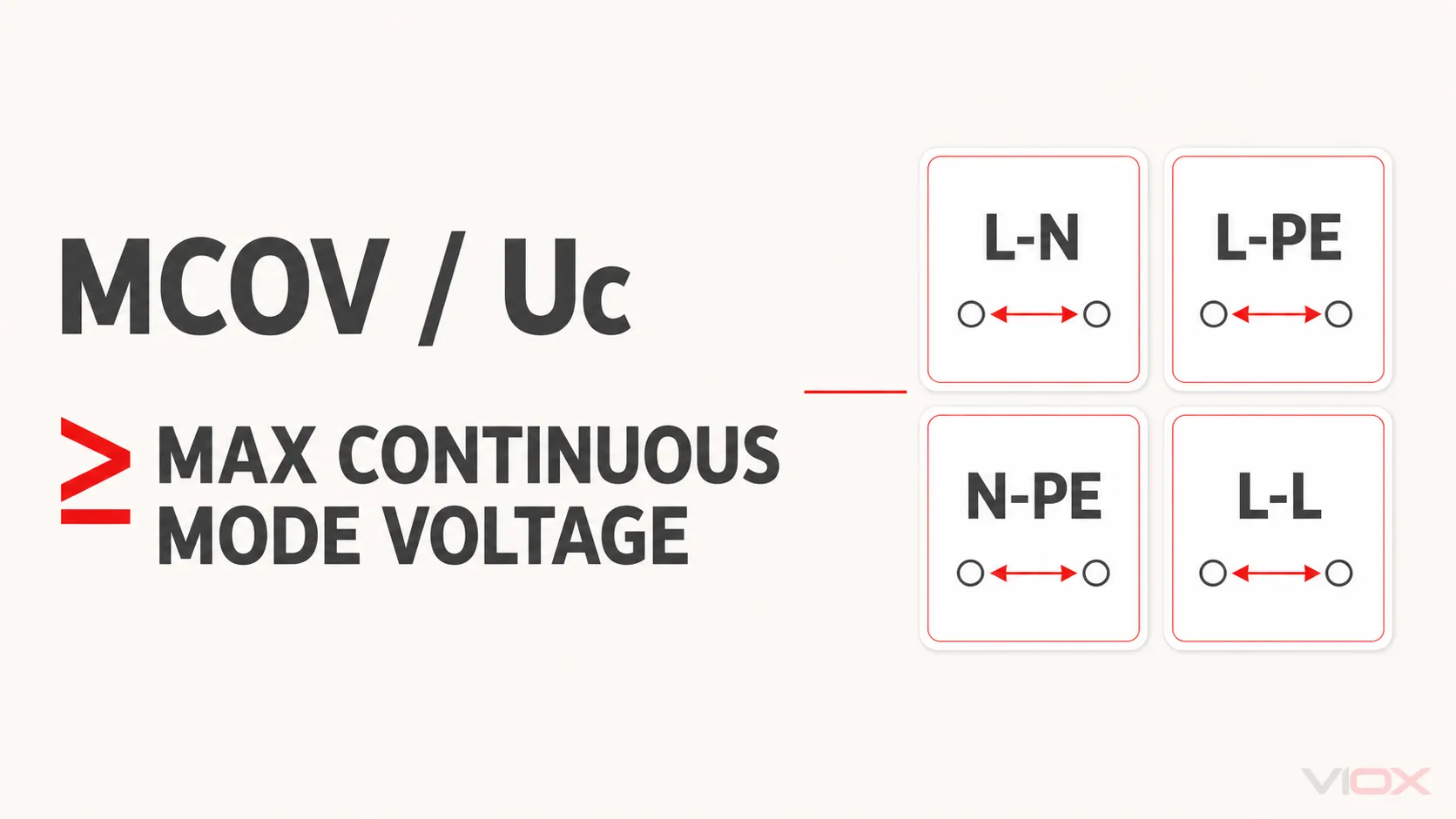
MCOV means maximum continuous operating voltage. In IEC documentation, the corresponding surge protective device (SPD) rating is normally written as Uc. It is the maximum RMS voltage that may be continuously applied across a stated SPD protection mode under its declared conditions.
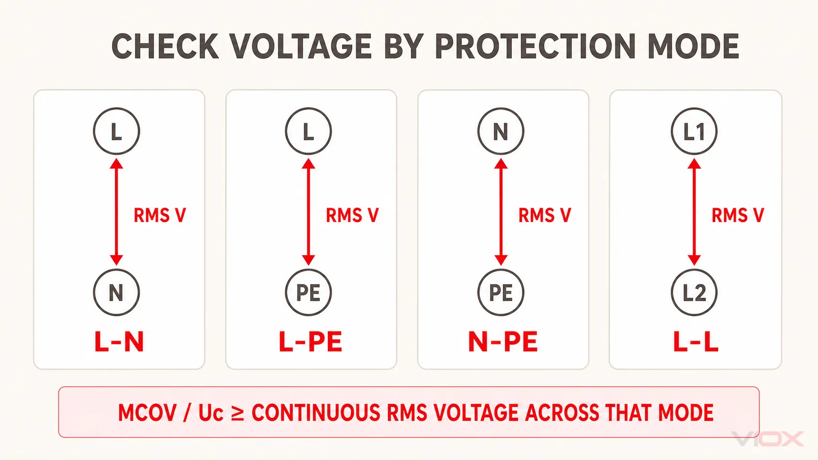
The practical rule is not “nominal voltage × one universal factor.” Select MCOV or Uc from the highest continuous power-frequency voltage that can appear across each connected mode—L-N, L-PE, N-PE, or L-L—then verify the earthing arrangement, credible normal voltage variation, the manufacturer’s TOV behavior, and the resulting Up or VPR.
If MCOV is too low, the SPD can experience excessive leakage, heating, aging, or disconnection. If it is unnecessarily high, the chosen device may have a less favorable voltage-protection level. The correct value is therefore the lowest declared rating that remains suitable for the real continuous-voltage and system conditions, not simply the largest number available.
MCOV and Uc in One Minute
| Term | Used mainly in | What it tells you | What it does not tell you |
|---|---|---|---|
| MCOV | North American and UL-oriented SPD literature | Maximum continuous operating voltage for a stated protection mode | The transient voltage left at the protected equipment |
| Uc | IEC-oriented SPD documentation | Maximum RMS voltage allowed continuously at the SPD terminals or mode | TOV withstand for every voltage and duration |
| Up | IEC-oriented documentation | Declared voltage protection level under specified surge tests | Continuous-voltage compatibility |
| VPR | UL-oriented documentation | Standardized voltage protection rating assigned by protection mode | MCOV or service-voltage suitability by itself |
MCOV is commonly stated in volts AC RMS for low-voltage AC SPDs. It is not the same as nominal system voltage, clamping voltage, Up, VPR, or a TOV withstand point. The Uc versus Up guide explains the parameter comparison in more detail; this page focuses on selecting the continuous-voltage rating.
IEC 61643-01:2024 contains common requirements and test methods for low-voltage SPDs and explicitly distinguishes a complete SPD, a mode of protection, and an SPD assembly. IEC 61643-11:2025 applies to AC low-voltage power SPDs and requires expected system, fault, and TOV stresses to be considered. IEC 61643-12:2020 addresses selection, operation, location, and coordination for AC power SPDs.
Why Nominal System Voltage Is Not Enough
A label such as “230/400 V,” “277/480 V,” or “480 V” does not identify the voltage across every SPD component. Four questions change the answer:
- Is the first number line-to-neutral and the second line-to-line, or is only line-to-line voltage stated?
- Is the source wye, delta, split phase, or another arrangement?
- How is the neutral or system reference grounded—solidly, through impedance, or not intentionally grounded?
- Which conductors does each SPD protection mode connect?
An SPD is exposed to voltage between its own terminals, not to the system nameplate as an abstract number. A device with L-N, L-PE, N-PE, and L-L modes may therefore publish different MCOV or VPR values by mode. UL’s public certification records, for example, list mode-specific MCOV and VPR values for evaluated SPDs rather than one interchangeable device-wide value.
Protection mode comes before the MCOV number
| Protection mode | Voltage to establish | Common selection error |
|---|---|---|
| L-N | Highest continuous line-to-neutral voltage at the installation point | Using line-to-line voltage without checking how the module is connected |
| L-PE | Highest continuous line-to-earth voltage, including the actual grounding arrangement | Assuming it always equals L-N in every system and fault condition |
| N-PE | Continuous and temporary voltage expected between neutral and protective earth | Treating N and PE as interchangeable everywhere in the installation |
| L-L | Highest continuous line-to-line voltage | Applying a line-to-neutral Uc value to a line-to-line protection element |
This is also why a “three-phase SPD” cannot be selected from phase count alone. The three-phase SPD sizing guide covers the complete specification; the 3-pole versus 4-pole SPD guide covers topology choices.
How Earthing and Source Topology Change MCOV Selection
In a solidly grounded wye system, line-to-neutral and normal line-to-earth voltages are usually based on the phase voltage, while line-to-line modes see the full line voltage. That relationship cannot be copied unchanged to a delta, IT, high-resistance-grounded, or otherwise impedance-grounded system.
During an earth fault, a healthy phase in an ungrounded or impedance-grounded system may rise substantially relative to earth. Whether that condition is treated as continuous service, a defined temporary overvoltage, or a fault that must clear within a specified time depends on the system design and applicable rules. The SPD selection must therefore use the manufacturer configuration table and TOV declaration for that arrangement—not an assumed 1.73 multiplier applied to every product.
For North American equipment, Eaton’s published SPD guidance illustrates the configuration dependency: it advises using a wye-configured SPD only where the neutral is physically connected and solidly grounded, and it routes impedance-grounded systems to an appropriate delta configuration. This is manufacturer application guidance, not a substitute for the exact product listing, system study, or local code.
For IEC applications, separate these two checks:
- continuous-voltage check: Uc must be suitable for the voltage continuously present across the connected mode;
- TOV check: the SPD’s declared response must suit the stated temporary voltage, duration, mode, and system condition.
Do not force the entire TOV magnitude into Uc unless the application documents require the SPD to remain continuously energized at that voltage. TOV withstand, safe failure, and continuous operation are different declarations. See the dedicated temporary overvoltage and SPD guide for that boundary.
Six Steps to Select MCOV or Uc for an SPD
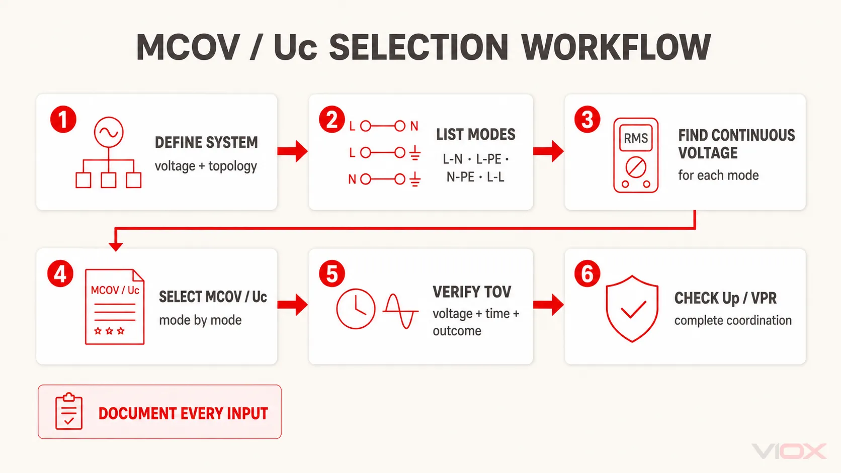
1. Record the electrical system, not only its nominal voltage
Document:
- AC or DC;
- nominal and highest expected continuous voltage;
- frequency and source type;
- single phase, split phase, wye, delta, or another topology;
- TN, TT, IT, solid grounding, or impedance grounding as applicable;
- neutral availability and bonding point;
- generator, UPS, converter, or alternate-source operating modes.
Do not infer the arrangement from conductor count or a panel label alone. Use the single-line diagram and verify the source and bonding scheme.
2. List every protection mode in the proposed SPD
Translate the product topology into actual terminal pairs. A 3+1 arrangement, for example, does not impose the same continuous voltage on every internal element as a 4+0 arrangement. The goal is a mode schedule such as:
| Mode | Connected conductors | Highest expected continuous RMS voltage | Candidate MCOV/Uc | Verified? |
|---|---|---|---|---|
| L1-N | L1 to N | project value | datasheet value | yes/no |
| L2-N | L2 to N | project value | datasheet value | yes/no |
| L3-N | L3 to N | project value | datasheet value | yes/no |
| N-PE | N to PE | project condition | datasheet declaration | yes/no |
This worksheet is intentionally blank. The correct figures belong to the actual installation and exact SPD datasheet.
3. Establish maximum continuous voltage for each mode
Use the highest credible power-frequency voltage that can remain present in normal service. Consider documented supply tolerance, transformer taps, voltage regulation, generator or UPS modes, and operating conditions relevant to the project.
A fixed 10%, 15%, or 25% margin may appear in a regional recommendation or a manufacturer’s worked example. It is not a universal IEC or UL selection formula. If a margin is used, record its source and confirm that it applies to the selected product and system.
4. Choose a declared MCOV/Uc that covers continuous operation
For every mode:
declared MCOV or Uc ≥ highest expected continuous RMS voltage across that mode
This inequality is a compatibility check, not a complete SPD selection formula. The chosen rating must also match the exact system configuration allowed by the manufacturer. Do not mix an MCOV stated for L-N with a different mode or assume one module value describes the complete assembly.
5. Verify TOV behavior separately
Check the product’s TOV table or curve for:
- applied voltage;
- duration;
- protection mode;
- earthing or fault condition;
- declared outcome, such as withstand or safe failure;
- required upstream or backup protection.
If the datasheet provides only “TOV resistant” without the condition and outcome, request the missing technical documentation. MCOV should not be inflated through a generic TOV multiplier to compensate for an unknown TOV declaration.
6. Recheck Up or VPR and the rest of the specification
An unnecessarily high MCOV/Uc can be associated with a higher limiting or protection level. Confirm that Up or VPR remains compatible with the equipment impulse withstand and the complete installation path. Then verify SPD Type, In, Imax or Iimp, short-circuit declaration such as SCCR or Isccr, backup fuse or breaker, connection length, status indication, and environmental ratings.
The SPD datasheet guide provides the complete acceptance sequence.
Worked Check 1: Grounded-Wye Distribution Board
Assume a project has a grounded-wye source and a proposed SPD with L-N, L-PE, N-PE, and L-L protection modes. The correct process is:
- record the system’s line-to-neutral and line-to-line voltages;
- establish the highest continuous voltage across each of the four mode types;
- verify that each mode’s declared MCOV/Uc is not lower than its respective continuous voltage;
- check the product’s TOV behavior for the actual earthing system;
- compare Up or VPR by mode with the protected equipment and installation design.
Published product records show why a single number is insufficient. One manufacturer may declare a lower MCOV for L-N and a higher value for L-L on the same system configuration. Those numbers are evidence for that exact model—not a lookup table for another SPD.
Worked Check 2: Delta or Impedance-Grounded System
For a three-wire delta or impedance-grounded system, do not start by dividing line-to-line voltage by √3. First determine which conductors and reference points the SPD actually connects, and what voltage each mode can experience during normal operation and relevant earth-fault conditions.
Then confirm that the exact SPD is listed or declared for that configuration. A slash-rated wye device or a product that requires a solidly grounded neutral cannot be assumed suitable merely because its numerical MCOV appears high enough. Configuration authorization and voltage rating are both required.
This example also shows why the former “grounded versus ungrounded MCOV formula” is unsafe: it can produce a plausible number while ignoring the product topology, mode-specific ratings, TOV outcome, and installation framework.
What Happens When MCOV Is Too Low or Too High?
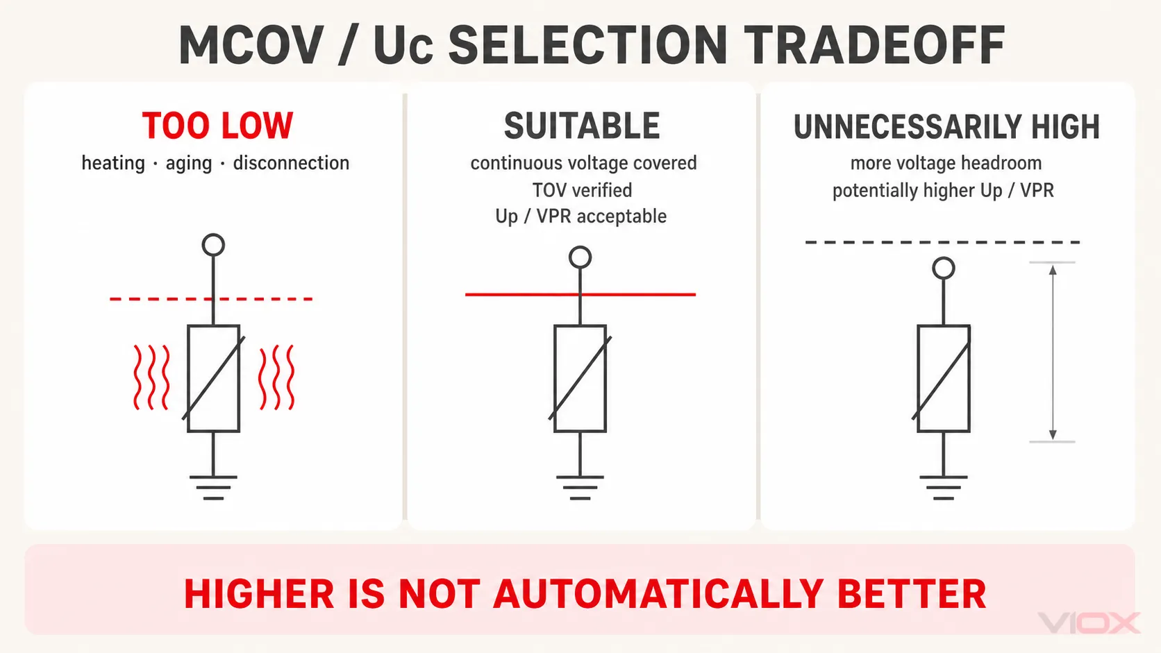
| Selection | Likely consequence | Engineering interpretation |
|---|---|---|
| Too low | Increased leakage, heating, accelerated MOV aging, thermal disconnection, or failure under normal or temporary voltage stress | Continuous-voltage compatibility is not met |
| Suitable | Stable operation at the highest expected continuous mode voltage, with documented TOV behavior and acceptable Up/VPR | The voltage-rating portion of the selection is defensible |
| Unnecessarily high | More continuous-voltage headroom, but potentially a higher Up/VPR or less favorable protection margin | “Higher” is not automatically “better”; recheck insulation coordination |
MCOV is also not a life rating. Surge history, thermal environment, internal component design, disconnector behavior, and surge-current duty affect service life. Do not use MCOV as a substitute for In, Imax, Iimp, or maintenance criteria.
Common MCOV Selection Errors
Treating MCOV as the clamping voltage
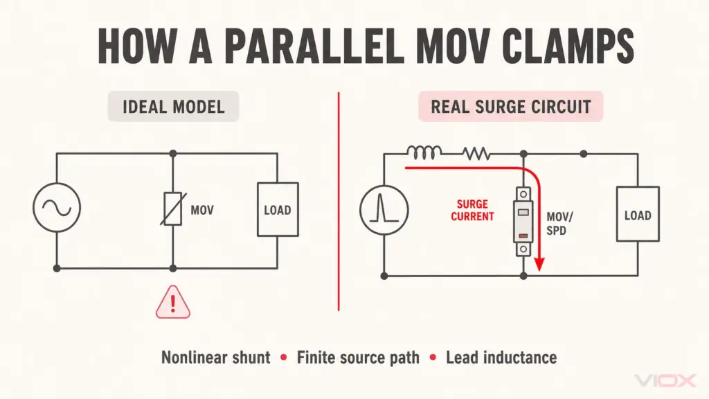
MCOV/Uc defines continuous-voltage compatibility. Up or VPR describes surge-voltage limitation under specified tests. The SPD’s nonlinear elements do not behave as an ideal switch at one exact MCOV threshold.
Selecting from nominal line voltage alone
The same nominal line voltage can describe different source and grounding arrangements. Select by voltage across the connected mode and the authorized system configuration.
Applying a universal TOV multiplier
TOV is defined by voltage, duration, protection mode, system condition, and outcome. Multiplying nominal voltage by one generic factor does not prove the product will withstand the expected event.
Copying another manufacturer’s table
Configuration labels and mode ratings are product-specific. Use the exact datasheet, instructions, certificate or listing record for the exact model and market.
Maximizing MCOV and ignoring Up or VPR
Excessive continuous-voltage headroom can weaken the protection-level decision. Select enough MCOV/Uc, then optimize the complete protective coordination.
Mixing low-voltage SPD and medium-voltage arrester rules
This guide concerns low-voltage power SPDs within the IEC 61643/UL 1449 context. Medium-voltage surge arresters use different standards, system studies, ratings, and TOV coordination. Their formulas and tables must not be imported into a low-voltage SPD specification.
MCOV/Uc Datasheet and RFQ Checklist
Before accepting an SPD, require one completed row for every protection mode:
| Required field | Acceptance question |
|---|---|
| Nominal system voltage | Does it describe L-N, L-L, or both? |
| Maximum continuous system voltage | What documented condition sets this value? |
| Source and earthing arrangement | Is the topology explicitly identified and permitted for the product? |
| Protection modes | Which terminal pairs are protected? |
| MCOV/Uc by mode | Is each value at least the continuous RMS voltage across that mode? |
| TOV declaration | Are voltage, duration, mode, condition, and outcome stated? |
| Up or VPR by mode | Is the protection level acceptable for the equipment and installation? |
| Short-circuit declaration | Is SCCR or the applicable IEC declaration such as Isccr coordinated with the installation and backup protection? |
| Product standard | Is the exact model evaluated to the applicable IEC, UL, or national framework? |
| Backup protection | Is the required fuse or breaker stated and available? |
If a supplier cannot provide mode-specific voltage data or the permitted system configuration, the MCOV number alone is not enough to approve the device.
Frequently Asked Questions
What does MCOV mean in electrical systems?
MCOV means maximum continuous operating voltage. For an SPD, it is the maximum RMS voltage that may be continuously applied across the stated protection mode under declared conditions.
Is MCOV the same as Uc?
They serve the same continuous-voltage selection purpose in common low-voltage SPD usage. Uc is the IEC symbol; MCOV is common in North American and UL-oriented literature. Always follow the terminology and test framework on the exact datasheet.
Should MCOV be higher than nominal voltage?
It must not be lower than the highest expected continuous RMS voltage across the relevant protection mode. Because nominal voltage does not include every operating variation, the declared MCOV/Uc is commonly above nominal—but the required difference must come from the actual system and applicable guidance, not a universal percentage.
Does MCOV need to be higher than TOV?
Not automatically. MCOV/Uc covers continuous operation. TOV behavior is assessed for a stated temporary voltage, duration, mode, and outcome. Verify the separate TOV declaration instead of treating every temporary value as a new continuous rating.
Is a higher MCOV SPD always better?
No. Higher MCOV can increase continuous-voltage tolerance, but may come with a higher Up or VPR. Choose sufficient continuous-voltage capability while maintaining the required surge-protection level.
Can MCOV be selected with a formula?
One equation can check whether MCOV/Uc is at least the highest continuous mode voltage, but no universal multiplier completes the selection. Topology, grounding, mode, TOV behavior, product authorization, and Up/VPR still need separate verification.
Selection Decision
Select MCOV or Uc mode by mode. Establish what voltage is continuously present across L-N, L-PE, N-PE, or L-L; verify that the exact SPD and topology are permitted for the source and earthing arrangement; then check TOV behavior and Up/VPR separately. This approach produces a defensible specification without hiding system assumptions inside a generic multiplier.
For an industrial SPD quotation, send VIOX the single-line diagram, nominal and maximum continuous voltages, frequency, source and earthing arrangement, required protection modes, SPD Type, TOV requirement, Up/VPR target, short-circuit level, and backup-protection details. Review available VIOX surge protective devices only after these system inputs are defined.
Technical References
- IEC 61643-01:2024 — Low-voltage surge protective devices, Part 01
- IEC 61643-11:2025 — SPDs connected to AC low-voltage power systems
- IEC 61643-12:2020 — AC power SPD selection and application principles
- UL Solutions — Overvoltage Protection
- UL Product iQ — public mode-specific SPD ratings example
- Eaton — Surge Protection FAQ
- Phoenix Contact — Fundamentals for Surge Protection
This guide supports specification review; it is not an energized testing or installation procedure. Final selection must follow the exact product documentation, system study, applicable installation rules, and qualified engineering review.