On this page
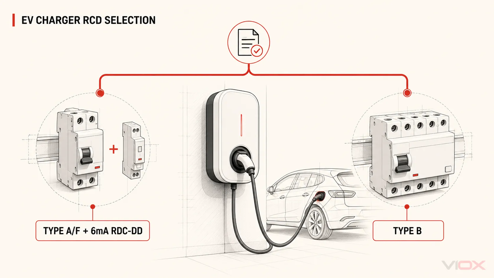
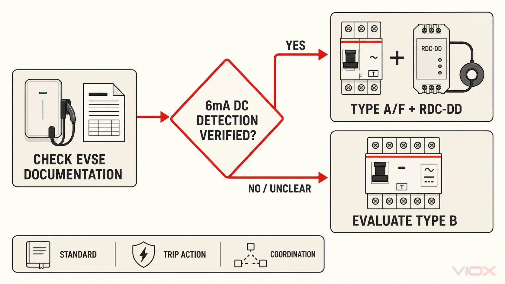
For a permanently connected Mode 3 AC EV charging circuit, do not choose the residual-current device from the words Type A, Type F, Type B, or 6mA alone. First verify whether the electric vehicle supply equipment (EVSE) includes a documented residual direct current detecting device (RDC-DD) that removes or initiates removal of the supply when smooth residual DC reaches 6 mA or more.
- If that IEC 62955 function is documented, an upstream Type A or Type F RCD may be possible when the charger instructions and applicable installation rules allow it.
- If the function is absent, outside scope, or not documented, evaluate a Type B RCD solution under the applicable rules and manufacturer instructions.
- Whichever strategy is used, the final specification must also define the device family, rated residual operating current, rated current, voltage, poles, associated overcurrent protection, and coordination evidence.
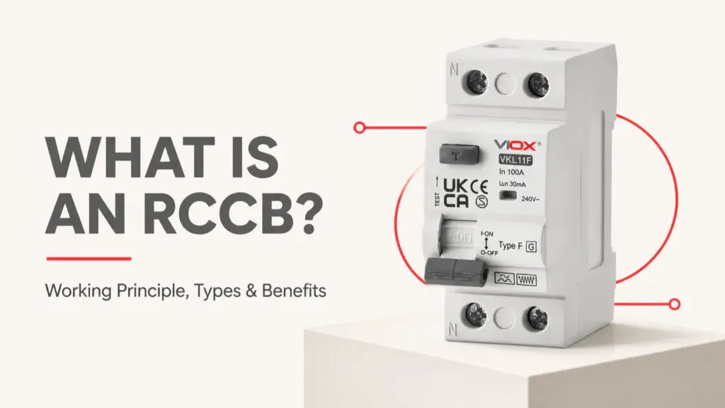
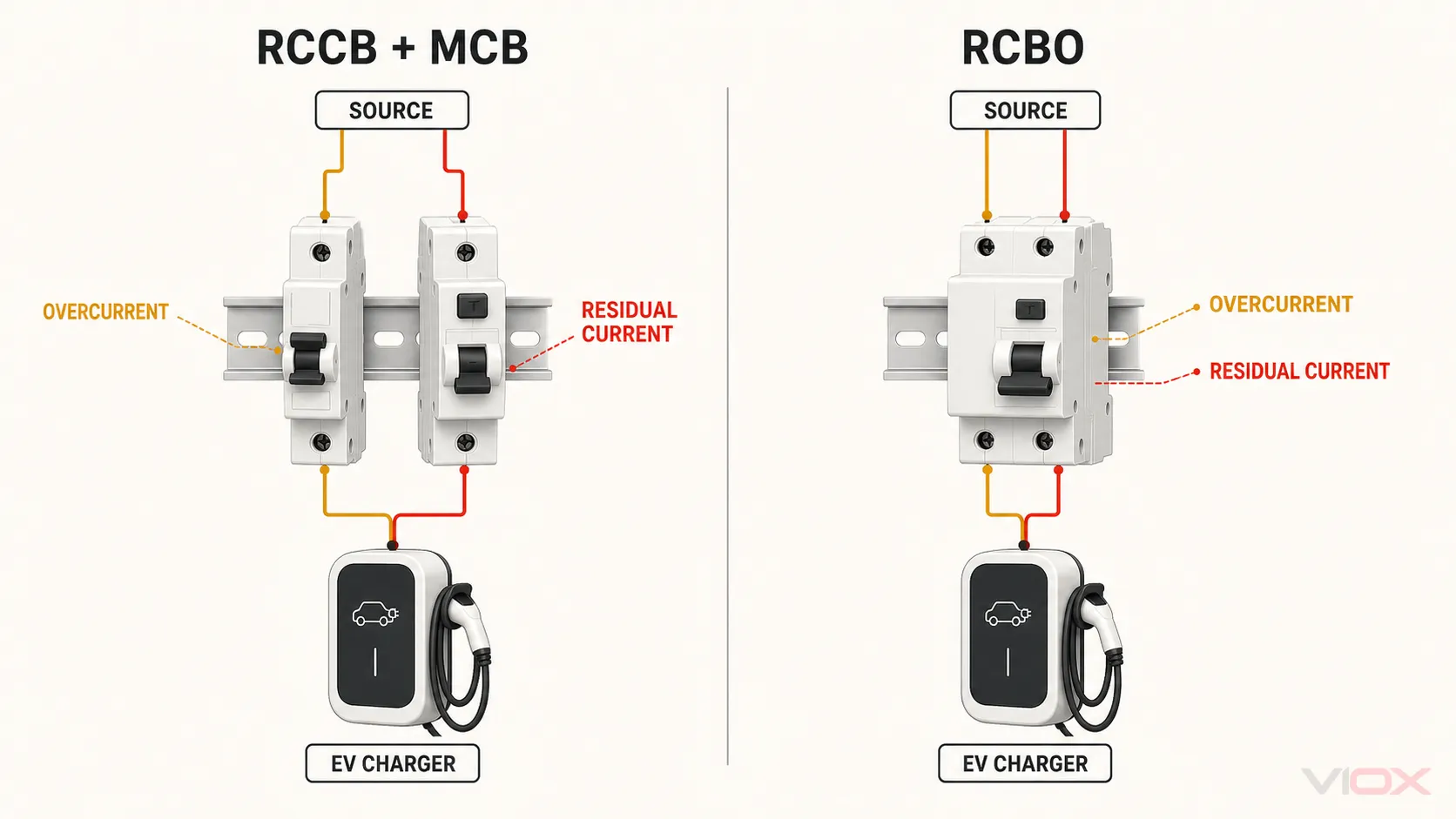
An RCCB is one form of Residual Current Device (RCD). It does not include integral overload or short-circuit protection, so an EV circuit using an RCCB also needs a coordinated MCB, fuse, or other overcurrent protective device.
EV Charger RCD Selection Worksheet
Complete this evidence table before comparing products. “Built-in DC protection” is not a complete answer unless the supporting document identifies what the function does and which upstream device the EVSE requires.
| Project input | Decision it controls | Required output | Evidence to verify |
|---|---|---|---|
| Charging mode and EVSE architecture | Whether IEC 62955 is within the intended scope | Mode 3 AC EVSE and protection arrangement | EVSE datasheet, installation manual, system single-line diagram |
| Smooth-DC detection function | Type A/F plus RDC-DD or Type B strategy | RDC-DD present, absent, or unverified | IEC 62955 declaration/certificate and exact EVSE reference |
| EVSE upstream-protection instruction | Permitted RCD type | Type A, Type F, Type B, or another documented arrangement | Exact manufacturer instruction, not a family-level brochure |
| Applicable installation rules | Individual RCD, IΔn, disconnection and regional requirements | Installation-rule compliance fields | Current national adoption and project specification |
| Supply and live conductors | Voltage, frequency and poles | Ue, frequency, pole arrangement | Single-line diagram and device instructions |
| Design current and duty | RCCB/RCBO current-carrying requirement | Rated current In | Load calculation and installation conditions |
| Overcurrent and fault conditions | RCCB + MCB/fuse or RCBO and backup coordination | Exact protective-device combination | Prospective short-circuit current and manufacturer coordination data |
| Upstream residual-current devices | Exposure to DC leakage and discrimination requirements | Upstream/downstream RCD architecture | Protection study and manufacturer selectivity/coordination data |
The result should be a written requirement, not a model number. Model comparison starts only after every field has an evidence source.
Step 1: Confirm the EVSE and Charging Arrangement
IEC 62955:2018 applies to RDC-DDs used with permanently connected AC Mode 3 EV charging stations within the standard’s stated voltage, frequency, and current scope. It does not automatically cover every portable charger, DC fast charger, bidirectional charging arrangement, or product advertised with a generic “DC leakage” feature.
Record:
- whether the circuit supplies a permanently connected Mode 3 AC EVSE;
- whether charging is single-phase or multiphase;
- whether the EVSE permits bidirectional power flow;
- the exact EVSE reference and installation-manual revision; and
- the destination market and applicable installation rules.
If the project falls outside the declared product-standard scope, do not stretch the selection table to fit. Use the applicable EVSE standard, installation rules, and manufacturer instructions for that architecture.
Step 2: Verify the 6mA DC Detection Claim
The purpose of an IEC 62955 RDC-DD is to detect smooth residual DC at or above 6 mA and remove or initiate removal of the EV supply. The 6 mA value is used so that the correct operation of an upstream Type A or Type F RCD is not impaired by smooth DC residual current.
Look for all of the following:
- the exact EVSE or RDC-DD model reference;
- an explicit IEC 62955 declaration, certificate, or report applicable to that reference;
- identification of the RDC-DD architecture and switching arrangement;
- the upstream RCD type required by the EVSE manufacturer;
- a diagram showing which device opens the circuit; and
- instructions for installation, functional verification, and fault reset.
Do not treat these statements as equivalent:
| Document wording | What it may establish | What remains unproven |
|---|---|---|
| “6mA DC detection” | A claimed detection threshold | IEC 62955 conformity, disconnection method, upstream RCD requirement |
| “RDC-DD according to IEC 62955” with exact model evidence | A relevant product-standard pathway | Installation compliance and coordination with the complete circuit |
| “Type EV” | A commercial EV-protection label | Whether the product is an RDC-DD, RCD, RCBO, or integrated assembly |
| “DC leakage sensor” | A monitoring function may exist | Whether it initiates safe disconnection and protects the upstream RCD as required |
For the standard boundary, classes, and document checks, use the dedicated IEC 62955 RDC-DD guide.
Step 3: Choose the Residual-Current Strategy
Type A plus documented RDC-DD
Type A RCDs cover sinusoidal AC and pulsating DC residual currents within their product definition. For Mode 3 EV charging, a Type A device may form part of the protection strategy when an appropriate RDC-DD prevents smooth DC above 6 mA from impairing it and when the EVSE instructions and applicable installation rules permit the arrangement.
The RDC-DD does not make the rest of the specification disappear. The upstream Type A device still needs the correct IΔn, rated current, poles, voltage, product standard, and overcurrent coordination.
Type F plus documented RDC-DD
IEC 62423 adds requirements for Type F RCDs intended for specified composite residual currents associated with certain single-phase frequency-converter loads. Type F is not a general substitute for Type B and should not be selected simply because an EV charger contains power electronics.
Use Type F only when:
- the EVSE or load documentation supports it;
- a suitable RDC-DD handles the smooth-DC condition;
- the supply arrangement falls within the device’s declared application; and
- applicable installation rules allow the complete strategy.
Type B protection
IEC 62423 Type B RCDs cover a broader set of residual-current waveforms, including smooth DC, within the standard and product definition. A Type B solution is the path to evaluate when the EVSE does not provide the required RDC-DD function, when its DC protection is unverified, or when the charger instructions, installation rules, or project specification require Type B protection.
Type B is not a universal upgrade that can be selected without coordination. The exact device still has rated-current, voltage, frequency, pole, time-characteristic, short-circuit, upstream-device, and installation constraints.
Decision summary
| Verified condition | Protection strategy to evaluate | Stop condition |
|---|---|---|
| EVSE has documented IEC 62955 RDC-DD and specifies Type A upstream | Type A RCD/RCCB or Type A RCBO, as permitted | Do not proceed if the model evidence or installation-rule fit is missing |
| EVSE has documented RDC-DD and specifically supports Type F | Type F RCD/RCCB or RCBO, as permitted | Type F alone does not supply smooth-DC detection equivalent to Type B |
| EVSE has no suitable RDC-DD | Type B residual-current protection | Verify exact architecture and applicable rules |
| DC protection is described only by marketing language | Treat the RDC-DD function as unverified | Request model-specific documents before selection |
| EVSE or installation rules specify a particular type | Follow that documented requirement | Do not substitute based on price or stock availability |
Step 4: Decide Between RCCB + MCB and RCBO
Residual-current type and overcurrent protection are separate decisions.
| Architecture | Residual-current function | Overload and short-circuit function | Verification focus |
|---|---|---|---|
| RCCB + MCB/fuse | Provided by the RCCB | Provided by the associated MCB or fuse | Exact RCCB–MCB/fuse coordination and fault-current evidence |
| RCBO | Integrated in one device | Integrated in the same device | Residual-current type, trip characteristic, breaking capacity and exact model standard |
| EVSE-integrated RDC-DD + upstream RCCB/RCBO | RDC-DD handles the smooth-DC condition; RCD handles required residual-current protection | Separate MCB or integral RCBO function | EVSE interface, upstream RCD type and the complete disconnection chain |
An RCCB alone is not a complete EV circuit protective device. If panel space or circuit isolation favors a combined device, review the VIOX RCBO selection guide, but verify that the RCBO has the required residual-current type rather than only the correct ampere rating.
Step 5: Complete the Electrical Ratings
Once the residual-current strategy is established, complete the remaining fields.
Rated residual operating current IΔn
Select IΔn from the applicable installation rules, protection objective, circuit position, and manufacturer instructions. Do not infer it from the RDC-DD’s 6 mA smooth-DC threshold: the two values describe different functions.
Rated current In
In is the current the RCCB is designed to carry under declared conditions; it is not an overload trip setting. Determine it from the EVSE load, duty, installation conditions, and coordination with the associated overcurrent device. For the load-calculation stage, use the separate EV charger circuit-breaker sizing guide.
Voltage, frequency, and poles
Match the declared supply and every live conductor that the device design requires to pass through the residual-current sensing arrangement. A 2-pole device is a common starting point for single-phase line-and-neutral circuits; a 4-pole device is common for three-phase circuits with neutral. The exact product diagram and installation rules control the final arrangement.
Short-circuit and overcurrent coordination
For an RCCB architecture, record the prospective short-circuit current and verify the exact RCCB with its associated or backup MCB/fuse using manufacturer data. Do not treat a conditional short-circuit value as proof that the RCCB independently interrupts that fault current.
Step 6: Check the Upstream RCD Architecture
The EV branch cannot be assessed in isolation when residual-current devices are connected in series. Smooth DC that remains below the downstream disconnection threshold can pass upstream, and multiple charging points may change the cumulative exposure. The permitted number and arrangement of downstream circuits depend on the device characteristics, charging architecture, manufacturer coordination data, and installation design.
Verify:
- whether another Type A or Type F RCD is upstream of the EV circuit;
- how many EV charging points are supplied through that upstream device;
- the maximum residual DC that can pass before each downstream device operates;
- threshold and time selectivity between residual-current devices;
- the effect of a common upstream trip on continuity of service; and
- manufacturer data for the exact combination.
Do not apply a universal rule such as “Type B can never be downstream of Type A” or “one RDC-DD always protects the upstream board.” Resolve the actual architecture with the applicable rules and documented device behavior.
Three Bounded Selection Scenarios
These examples demonstrate the workflow; they are not universal prescriptions.
| Project evidence | Preliminary result | Documents still required |
|---|---|---|
| Single-phase Mode 3 EVSE; exact manual declares IEC 62955 RDC-DD and specifies upstream Type A | Evaluate a correctly rated Type A RCCB + MCB or Type A RCBO | EVSE certificate, RCD/RCBO datasheet, circuit ratings, local rules, coordination evidence |
| EVSE manual declares an IEC 62955 RDC-DD and specifically permits Type F for its single-phase converter behavior | Evaluate Type F with the documented RDC-DD architecture | Exact Type F device scope, EVSE instructions, local rules and overcurrent coordination |
| EVSE has no documented 6 mA RDC-DD or the evidence does not apply to the proposed model | Evaluate Type B residual-current protection | Type B model documents, upstream coordination, overcurrent protection and installation-rule review |
If the charger reference, firmware/hardware variant, or manual revision changes, repeat the evidence check. A feature offered on one EVSE variant is not proof that every product in the family includes it.
EV Charger Protection Specification Template
Project and destination market:
EVSE manufacturer / exact reference / document revision:
Charging mode and direction of power flow:
Supply voltage / frequency / phases / neutral:
Design current and duty:

Declared RDC-DD function: present / absent / unverified
IEC 62955 evidence reference:
RDC-DD architecture and switching-device reference:
EVSE-required upstream RCD type:

Selected device architecture: RCCB + MCB/fuse / RCBO / other verified arrangement
Residual-current type: A / F / B / other verified type
Rated residual operating current IΔn:
Rated current In:
Poles and terminal arrangement:
Time characteristic:

Associated overcurrent protective device:
Prospective short-circuit current:
Conditional short-circuit / backup evidence:
Upstream RCD and selectivity evidence:

Applicable installation rules:
Required certificates, reports, diagrams, and commissioning instructions:
Only after this specification is complete should the project team compare the available VIOX RCCB range or VIOX RCBO range. Send the EVSE manual, single-line diagram, destination market, electrical ratings, quantity, and required documentation to [email protected] for a model-document review.
Focused Questions
Does every EV charger need a Type B RCCB?
No universal answer applies. A documented IEC 62955 RDC-DD may allow Type A or Type F upstream protection where the EVSE instructions and applicable installation rules permit it. Without suitable smooth-DC protection evidence, Type B is the strategy to evaluate.
Is a built-in 6mA sensor enough to use Type A?
Not from that phrase alone. Verify the exact model’s IEC 62955 evidence, disconnection architecture, upstream RCD instruction, and applicable installation rules.
Is Type F the same as Type B for EV charging?
No. Type F covers specified composite residual currents associated with certain single-phase frequency-converter loads. It does not provide the same smooth-DC residual-current capability as Type B, so an appropriate RDC-DD is still needed where the strategy relies on Type F.
Is “Type EV” an official RCCB waveform type?
Do not assume so. The term is used commercially for different EV-protection arrangements. Identify whether the product is an RDC-DD, an RCD/RCBO with integrated functions, or another assembly, and verify its exact standard documents.